1. Introduction
Intense optical pulse propagating in a medium with second-order nonlinearity can emit electromagnetic waves, a phenomenon similar to the classical Cherenkov radiation from a moving charged particle [
1,
2]. Cherenkov-type emission of terahertz waves by femtosecond laser pulses in electro-optic crystals has become an established way of terahertz generation [
3,
4,
5,
6]. The Cherenkov generation scheme has an advantage of inherently providing noncollinear phase-matching of generated terahertz waves with the pump laser pulse in materials with optical-terahertz velocity mismatch, even with a very large one as in LiNbO
. Since LiNbO
was considered as the material of choice for terahertz generation, owing to its high second-order nonlinear coefficient and high damage threshold, the Cherenkov scheme was primarily elaborated in application to this crystal [
7]. To avoid strong terahertz absorption in LiNbO
, it was proposed to extract Cherenkov radiation from the crystal through its lateral surface by means of a Si prism outcoupler [
8]. To reduce the transverse size of the pump optical beam, which determines the Cherenkov radiation bandwidth [
9], and simultaneously suppress diffraction broadening of the beam, LiNbO
planar and ridge waveguides are used [
10,
11]. The waveguide structures with micron-size layers or ridges of LiNbO
[
12,
13,
14] have a drawback of low coupling efficiency of the pump laser beam to the waveguide. This significantly limits the overall optical-to-terahertz conversion efficiency. Much more efficient are the converters with a tens of microns thick layer of LiNbO
[
15,
16,
17,
18]. In particular, they provide record high efficiencies (∼1% [
17]) of converting sub-mJ energy laser pulses. However, an inherent drawback of the converters with a tens of microns thick layer of LiNbO
is a notch in the generated spectrum originating from the destructive interference of the terahertz waves emitted to the Si prism outcoupler from the LiNbO
layer directly and after reflection from the substrate [
19]. For example, the converter with a 45
m thick layer of LiNbO
attached to a Si prism has an interference notch at 1 THz [
19].
Recently, a Cherenkov-type converter with a layer of LiNbO
sandwiched between two totally reflecting Si prisms was introduced [
20]. In this converter, terahertz radiation is emitted from the LiNbO
layer through its two lateral surfaces and internally reflected in the prisms to produce a single collimated terahertz beam. Due to bilateral emission, there is no interference notch in the generated terahertz spectrum. Additionally, the converter design provides a suppression of the timing jitter of the generated terahertz pulses caused by the pump laser beam pointing instability [
21].
Typically, Cherenkov-type converters are pumped by amplified laser systems with tens or hundreds of microjoules pulse energy using cylindrical focusing geometry. For spectroscopic applications, however, pumping by an optical oscillator with a lower (at the nanojoule level) pulse energy but higher (∼100 MHz, rather than ∼1 kHz) repetition rate may be preferable due to potentially higher signal-to-noise ratio. Pumping by an optical oscillator requires using a standard spherical focusing geometry to provide high optical intensity necessary for efficient optical rectification. In the regime of spherical focusing, Cherenkov radiation geometry changes from two-dimensional to three-dimensional, i.e., a cone of terahertz waves is generated rather than a wedge, as in the regime of cylindrical focusing. Thus, the operating conditions of the converter change significantly [
22].
In this paper, we demonstrate experimentally that the Cherenkov-type converter with bilateral emission of terahertz radiation through two totally reflecting Si prisms can efficiently convert optical pulses from an optical oscillator. In particular, it can surpass the conventional collinear conversion scheme with a ZnTe crystal in efficiency by an order of magnitude. Moreover, the converter has an advantage of workability with pump lasers of different wavelengths.
2. Experimental Setup and Methods
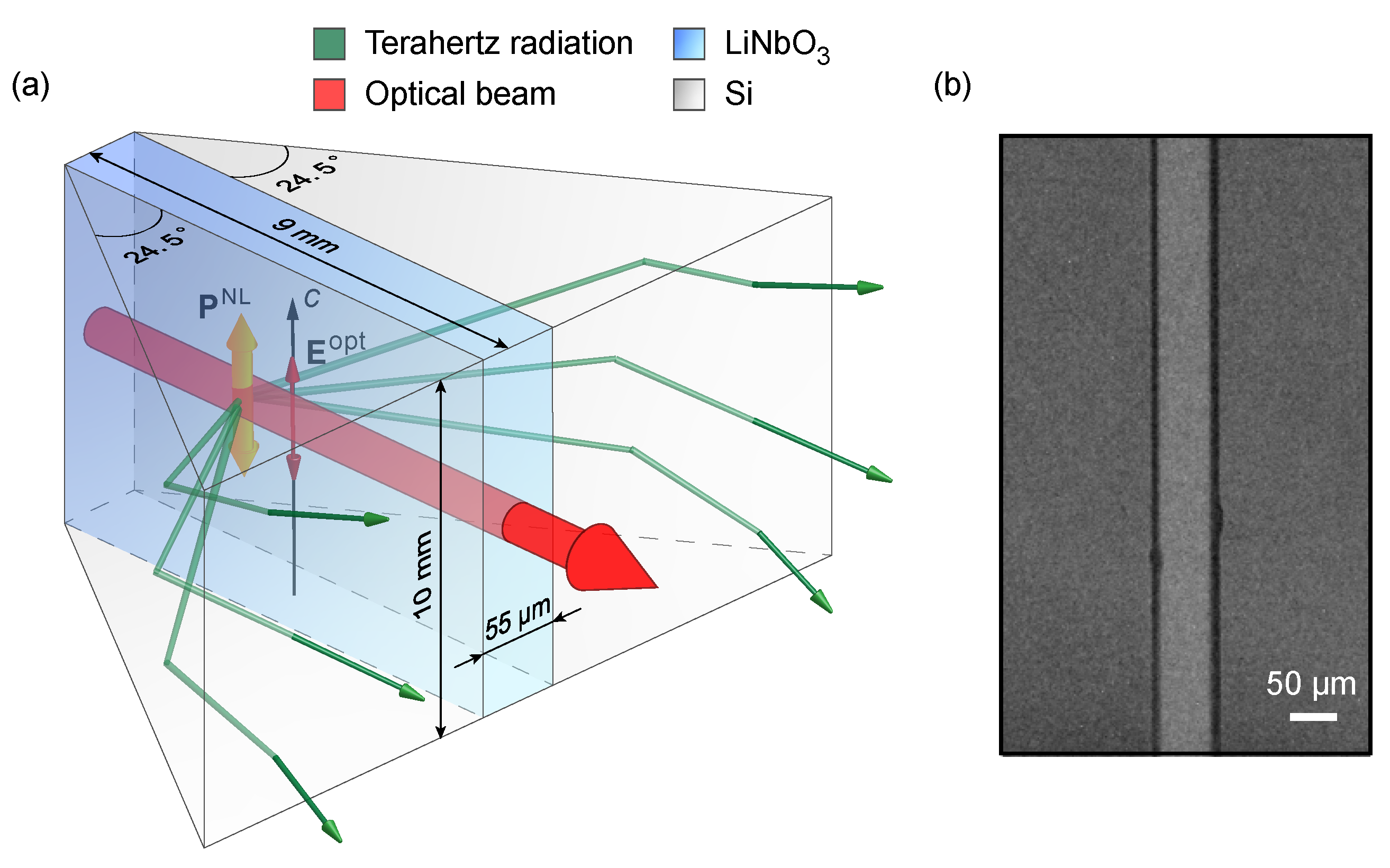
In experiments, we used a structure with a 55
m thick, 1 cm wide, and 9 mm long layer of LiNbO
placed between two prisms made of high-resistivity Si (
Figure 1a), the same as in ref. [
20]. To fabricate the structure, a 1 mm thick plate of MgO-doped congruent LiNbO
was glued to one of the prisms by a two-component epoxy adhesive. The thickness of the adhesive layer after drying was about 6–8
m. Then, the LiNbO
plate was ground down to 55
m and its surface was polished. After that, the second prism was glued to the surface. Finally, the entrance and exit facets of the LiNbO
layer were also polished. A microscopic photograph of the entrance face of the Si-LiNbO
-Si structure is shown in
Figure 1b.
The presence of the buffer adhesive layers at the LiNbO
-Si boundaries is, on the one hand, beneficial for preventing the penetration of the optical pump radiation to Si and generation of free carriers that absorb terahertz radiation. Indeed, the optical refractive index of the adhesive (about 1.55) is lower than that of LiNbO
(about 2.2) and, therefore, the LiNbO
layer operates as a parallel slab waveguide for pump radiation. On the other hand, the adhesive layer should be thin enough to reduce the effect of total internal reflection at the LiNbO
–adhesive boundary for the generated terahertz radiation. The intensity decay length of terahertz radiation in the adhesive layer is determined by formula
[
19], where
is the terahertz (vacuum) wavelength,
is the optical group refractive index of LiNbO
, and
is the terahertz phase refractive index of the adhesive. By using
at the wavelength (≈800 nm) of a Ti:sapphire laser [
23,
24] and
(measured by means of terahertz time-domain spectroscopy (THz-TDS)), the decay length is estimated as
m at
m (1 THz frequency) and only ≈5
m at
m (3 THz frequency). Thus, the thickness of the adhesive layers is a limiting factor for converter bandwidth. For the adhesive we used, it was challenging to make the adhesive layers thinner than 6–8
m because of high adhesive viscosity.
In
Figure 1a, the optical (
c) axis of LiNbO
is in the plane of the crystal layer and perpendicular to the propagation direction of the pump light. The polarization of the laser beam is along the
c-axis, which is the optimal polarization for optical rectification in LiNbO
[
25]. Second-order nonlinear polarization
induced in the crystal via optical rectification is also directed along the
c-axis. Nonlinear polarization co-propagates with the optical pump pulse and acts as a source of terahertz waves.
Unlike ref. [
20], the structure was pumped by a spherically focused beam from an optical oscillator rather than a cylindrically focused beam from an amplified laser system. Due to spherical focusing, the pulse of nonlinear polarization generates a Cherenkov cone, rather than a wedge [
20], of terahertz waves in the Si prisms. The emission angle of Cherenkov radiation in the Si prisms is determined by formula
, where
is the terahertz phase refractive index of Si. Using
at the pump wavelength of ≈800 nm and
[
26], the Cherenkov angle is estimated as
. The prism apex angle is made equal to
(
Figure 1a). Such design provides total internal reflection of terahertz radiation at the Si–air boundaries (prism hypotenuses) and their collimation along the pump beam in the plane orthogonal to the
c-axis [
20]. Strictly speaking, there is no such collimation for other parts of the Cherenkov cone. However, the distribution of radiation over the Cherenkov cone is strongly inhomogeneous [
22,
27]: the radiation is emitted predominantly at moderate angles to the direction perpendicular to
(the
c-axis), i.e., rather closely to the plane of perfect collimation. Additionally, the acceptance angle of the output prisms is
to the plane orthogonal to the
c-axis. This angle is determined by the angle of total internal reflection (
) at the prism output face. Therefore, one can expect that the prisms couple Cherenkov radiation from the LiNbO
layer to free space radiation rather efficiently even in the case of pumping by a spherically focused laser beam. This is confirmed experimentally.
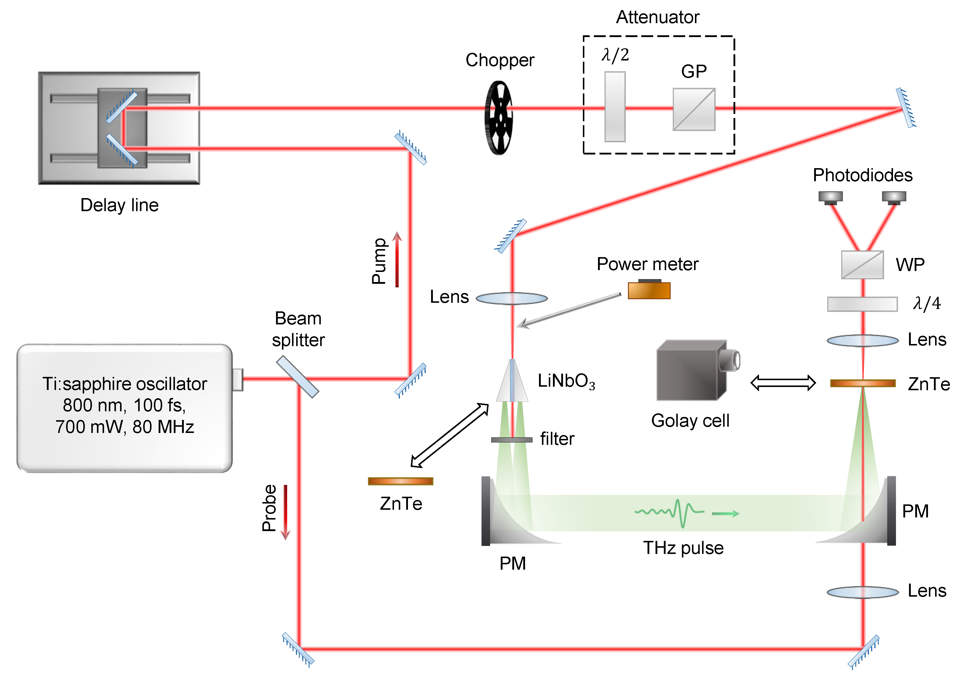
A schematic diagram of the experimental setup is shown in
Figure 2. A femtosecond Ti:sapphire oscillator (Tsunami, Spectra-Physics) with an 800 nm wavelength, a 100 fs pulse duration, an 80 MHz repetition rate, and a 700 mW average power (8.7 nJ pulse energy) was used as a light source. The laser beam was divided into a stronger (640 mW power) pump beam and a weaker (30 mW) probe beam. A half-wave plate (
) and a Glan prism (GP) were used to control the optical power delivered to the converter. Due to losses in optical elements, the maximum optical power at the converter input was about 350 mW (4.4 nJ pulse energy). The pump beam of a 0.7 mm diameter (full width at half maximum (FWHM)) was focused by a spherical lens (5 or 7.5 cm focal length) to a spot (∼25 or 38
m FWHM) on the entrance facet of the LiNbO
layer. Pump beam polarization was along the
c-axis of the crystal (out-of-plane direction in
Figure 2). The transmitted pump beam was blocked by a filter. Terahertz radiation emitted from the converter was collected, collimated, and focused by a pair of parabolic mirrors (PM, 5 cm focal length) to a 1 mm thick ZnTe detector crystal with its [001] crystallographic axis being in the in-plane direction in
Figure 2 and orthogonal to the terahertz electric field and probe beam polarization. The conventional electro-optic sampling detection scheme including also a delay line, a quarter-wave plate (
), a Wollaston prism (WP), and a pair of photodiodes was used for measuring the terahertz waveform. Terahertz power was measured by a calibrated Golay cell with a diamond window (Tydex) placed into position of the detector crystal and screened from stray optical radiation by a Si wafer. Calibration was performed immediately after the measurements with use of a strongly (several hundred times) attenuated laser radiation and optical power meter (Thorlabs). A chopper and lock-in amplifier were used both in electro-optic and power measurements. Chopper modulation frequency was 300 and 15 Hz for electro-optic and power measurements, respectively.
To adjust the orientation and position of the converter with respect to the pump laser beam and its focal region, the Golay cell was placed (instead of the first PM) in the vicinity of the converter’s output face. The converter was shifted along and across the laser beam and rotated in the plane of
Figure 2 to maximize the signal from the Golay cell. After that, the parabolic mirror was set at a distance of about the mirror focal length (5 cm) from the converter’s output face and the Golay cell was placed at a distance of about 1 m from the parabolic mirror in the direction of a 90
reflection by the mirror. By adjusting the mirror, a weakly convergent terahertz beam was formed. Then, the second parabolic mirror was set at a distance of about 30 cm from the first mirror. The Golay cell was moved to the focal region of the second mirror and the orientation of the second mirror was adjusted to maximize the Golay cell signal. To align the terahertz and probe optical beams in the detector crystal, the crystal was replaced by a diaphragm of a small (about 1 mm) diameter and the Golay cell was set behind the diaphragm. By maximizing the Golay cell signal (in the absence of the probe beam), the position of the diaphragm was adjusted with respect to the terahertz beam. Then, the probe beam was aligned with the diaphragm.
For comparison, the Cherenkov converter was replaced by a 0.5 mm thick <110>-cut ZnTe generator crystal with its [001] crystallographic axis oriented perpendicularly to the pump beam electric field. Such orientation provides only slightly (≈15%) lower terahertz generation than the optimal orientation with a ≈
angle between the [001] axis and pump beam polarization [
28]. At the same time, it is more convenient for practical use [
29]. Since the ZnTe crystal generated terahertz radiation with the electric field in the in-plane direction in
Figure 2, the detector crystal was rotated, after changing the generator type, by 90
around the terahertz beam direction for optimal detection [
28].
3. Results and Discussion
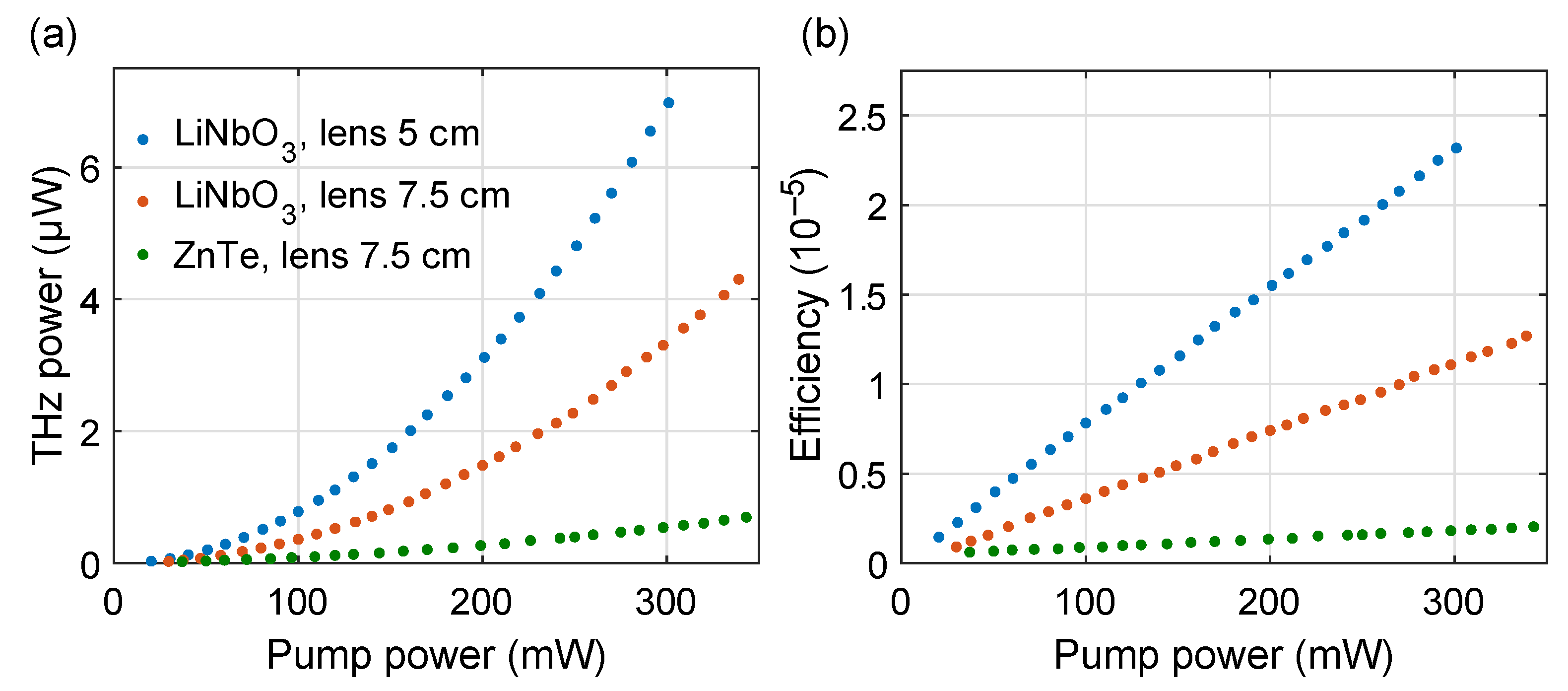
Figure 3 shows the dependencies of the terahertz power (
Figure 3a) and optical-to-terahertz conversion efficiency (
Figure 3b) on the pump power for two focusing conditions. The curves demonstrate the typical behavior for second-order nonlinear optical rectification, i.e., quadratic in
Figure 3a and linear in
Figure 3b, with no indication of saturation. Terahertz generation is more efficient for tighter focusing (by a 5 cm focal length lens), with the maximum efficiency of ≈
at a 300 mW pump power (3.75 nJ pulse energy). This value is somewhat smaller than the efficiency of
reported in ref. [
22] for a Cherenkov-type converter with unilateral terahertz emission. The lower efficiency can be explained by using a thicker (55
m, rather than 35
m, thick) LiNbO
layer in the bilateral converter (
Figure 1a), which results in stronger absorption of terahertz waves in the crystal and less efficient generation of higher frequencies due to destructive interference of the terahertz waves emitted from different points of the pump beam cross-section [
9,
10].
For the same focusing conditions (with a 7.5 cm focal length lens), the LiNbO
-based Cherenkov-type converter is approximately six times more efficient than the conventional scheme with a ZnTe crystal (
against
at a 350 mW pump power in
Figure 3b). The higher efficiency of the converter can be mainly attributed to a larger second-order nonlinear coefficient of LiNbO
: 168 pm/V [
30,
31] versus 68.5 pm/V for ZnTe [
30]. Importantly, a significantly shorter optical-terahertz coherence length in LiNbO
(∼100
m versus several millimeters in ZnTe [
32,
33]) is compensated by using the Cherenkov radiation scheme.
It is interesting to compare the converter efficiency for two operating regimes, i.e., for spherical and cylindrical focusing of the pump laser beam. In the regime of cylindrical focusing [
20], the efficiency of
was achieved at 40
J/cm of pump pulse energy per unit length of the focal line (see Figure 5 in ref. [
20]). The corresponding pump fluence can be calculated by using the focal line width (≈25
m [
20]) and is equal to 15 mJ/cm
. Due to the absence of saturation at such a fluence level [
20], the efficiency is directly proportional to the fluence. Therefore, one can calculate the efficiency for the fluence of 0.5 mJ/cm
, which corresponds to the conditions of our experiment for the pump beam power of 300 mW and the lens focal length of 5 cm. The calculated efficiency,
, is about three times higher than the corresponding efficiency in
Figure 3b. This can be explained by a conical emission of terahertz waves from a spherically focused laser beam. A part of terahertz waves, emitted at angles larger than
to the plane orthogonal to
, experiences total internal reflection at the output faces of the Si prisms. The waves emitted at smaller angles form a divergent terahertz beam at the converter output (
Figure 1a), which is only partially collected by the parabolic mirror. Although the spherical focusing is about three times less efficient than the cylindrical one, it is unavoidable in the case of pumping by an oscillator. Moreover, the losses at the output faces can be completely eliminated by improving the converter design, namely by changing the Si prisms to Si half-cones with the opening angles of 24.5
. Such half-cones match the conical geometry of Cherenkov emission and form a collimated terahertz beam at the converter output in the regime of spherical focusing of the pump laser beam.
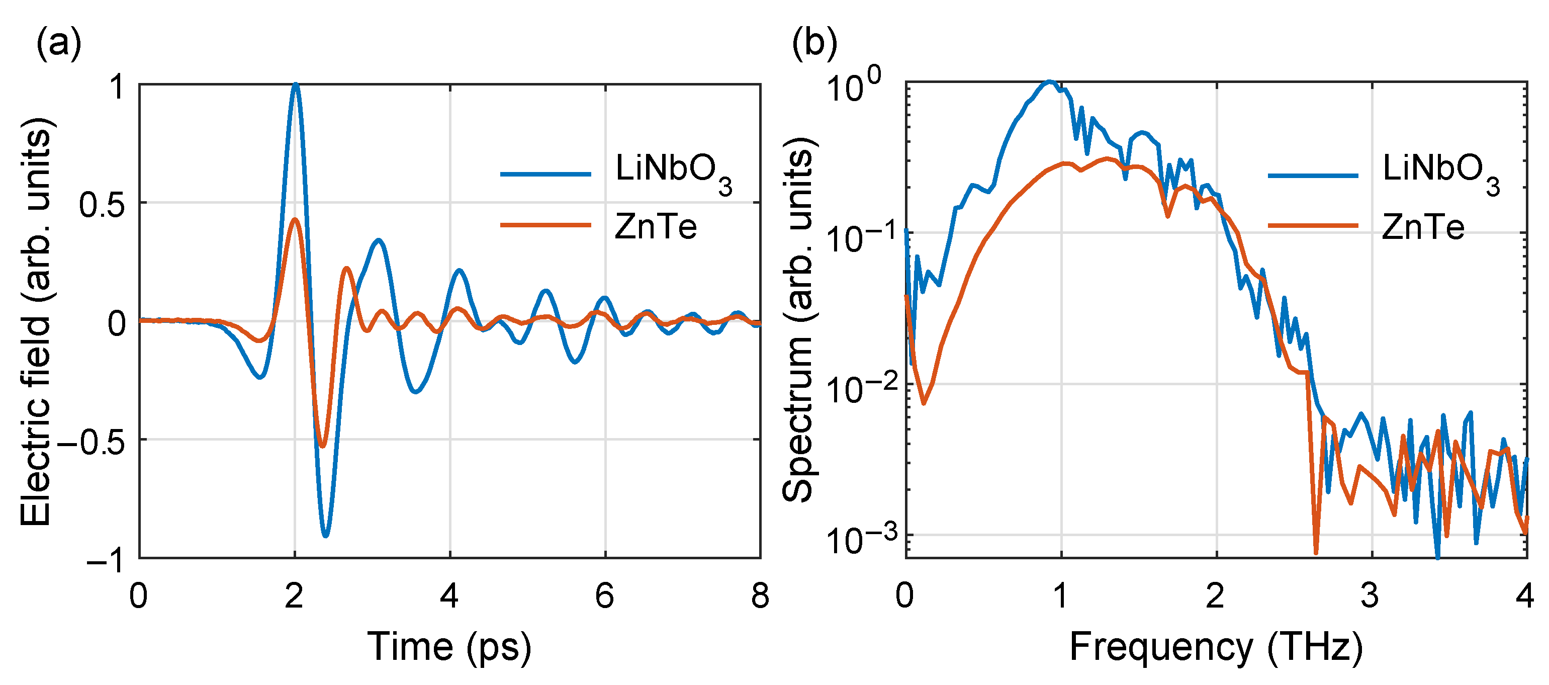
Figure 4 shows the waveforms (
Figure 4a) and spectra (
Figure 4b) of terahertz emissions from the LiNbO
-based converter and the ZnTe crystal. In
Figure 4a, the peak-to-peak amplitude of the terahertz field from the converter is twice higher than the one from the ZnTe crystal. The gradually fading oscillations in the converter’s waveform can be attributed to multiple reflections of terahertz waves within the thin LiNbO
layer. In general, the difference in the waveforms agrees well with the results of the energetic measurements (
Figure 3a).
In
Figure 4b, there is no interference notch in the converter’s spectrum, contrary to the unilateral Cherenkov converter [
22]. The spectrum width (≈2.7 THz) is the same as for the 0.5 mm thick ZnTe generator crystal. However, the converter’s spectrum is strongly enhanced at frequencies below 1.5 THz (about five times at 1 THz). The identical spectrum width for the two much different terahertz generation schemes, i.e., a noncollinear scheme with Cherenkov-type LiNbO
-based converter and a collinear scheme with a ZnTe crystal, can be attributed to the limited bandwidth of the 1 mm thick ZnTe detector crystal. Indeed, the terahertz sensitivity of a 1 mm thick ZnTe detector crystal exhibits fast roll-off with approaching the detection frequency of 3 THz due to a decrease in optical-terahertz coherence length [
34] and increase in terahertz absorption [
35].
To characterize the performance of the converter in the terahertz time-domain spectrometer (
Figure 2), we estimated the dynamic range [
36] from
Figure 4b. It is higher for the converter (about 49 dB) than for the ZnTe crystal (42 dB).
Thus, the LiNbO
-based Cherenkov-type converter with bilateral terahertz emission surpasses the conventional collinear terahertz generation scheme with a ZnTe crystal both in efficiency and dynamic range. The converter’s efficiency can be further enhanced by reducing the thickness of the LiNbO
layer due to (i) decrease in terahertz absorption and (ii) suppression of the destructive interference of the terahertz waves emitted from different points of the pump beam cross-section [
9,
10]. Both factors also broaden the generated spectrum. However, using a thinner LiNbO
layer implies tighter focusing of the pump beam. For spherical focusing, this shortens the terahertz-emitting focal region due to diffraction divergence of the pump beam in the plane of the LiNbO
layer. Besides reducing the emission, the shortening enhances diffraction divergence of the output terahertz beam and, as a result, hinders the collection of the beam by the parabolic mirror. By taking all the above-mentioned factors into account, the optimal focal spot size is estimated as ≈20
m [
27]. The spot size puts a limitation on reducing the LiNbO
layer thickness. This limitation can be mitigated by using two cylindrical lenses with different focal lengths to focus the pump beam loosely in the plane of the layer and tightly in the perpendicular plane. In this case, a reasonable thickness of the LiNbO
layer is ≈10
m to provide efficient excitation of the fundamental waveguide mode in the layer by the pump beam [
10].
Importantly, since the optical group refractive index of LiNbO
does not vary significantly with wavelength in the interval 0.8–2
m [
23,
24], the Cherenkov angle in the converter’s Si prisms remains almost the same for different pump wavelengths from this interval. Therefore, one can expect that the same converter is able to operate with not only Ti:sapphire laser but also with convenient Yb-doped (1.06
m wavelength) and Er-doped (1.55
m wavelength) fiber lasers [
37].


