Article

Optical Filter Design for Daylight Outdoor Electroluminescence Imaging of PV Modules

School of Physics, Engineering and Technology, University of York, York YO10 5DD, UK
*
Author to whom correspondence should be addressed.
Photonics 2024, 11(1), 63; https://doi.org/10.3390/photonics11010063
Submission received: 7 December 2023 / Revised: 2 January 2024 / Accepted: 5 January 2024 / Published: 7 January 2024
(This article belongs to the Special Issue Optical Spectroscopy and Applications)

Abstract

:
This paper presents an advanced outdoor electroluminescence (EL) imaging system for inspecting solar photovoltaic (PV) modules under varying daylight conditions. EL imaging, known for its effectiveness in non-destructively detecting PV module defects, is enhanced through specialized optical filters. These filters, including a bandpass filter targeting EL emissions and a neutral density filter to reduce background light, significantly improve the system’s signal-to-noise ratio (SNR). The experimental results demonstrate the system’s enhanced performance, with superior clarity and detail in EL emissions, enabling precise defect localization and characterization at the cellular level. Notably, the system achieves an SNR improvement, with values consistently above two, outperforming previous systems and confirming its suitability for efficient solar PV maintenance and diagnostics. This research offers a flexible approach to optimizing EL imaging quality across various solar irradiance levels and angles, essential for improved PV module performance and reliability. The system effectively handles different PV module configurations, orientations, and types, including monofacial and bifacial arrays. It showcases robust imaging capabilities under high solar irradiance and different sun illumination levels, maintaining high-quality imaging due to its optimized filter design. Additionally, the system’s adaptability in detecting EL emissions from series-connected PV modules is highlighted, demonstrating its comprehensive evaluation capabilities for PV array performance.

1. Introduction

Solar photovoltaic (PV) systems are becoming increasingly essential as a source of renewable energy. However, as with all renewable energy systems, solar PV systems require regular inspection and maintenance to ensure that they are functioning optimally and safely. Inspection methods for solar PV systems typically involve a combination of visual inspection, electrical testing, and performance analysis.
Visual inspection involves a thorough examination of the solar PV modules, mounts, and associated components for signs of damage, such as cracks, corrosion, or loose connections [1,2,3]. Electrical testing involves measuring the electrical parameters of the system, such as voltage and current [4], to ensure that the system is producing the expected amount of power and that there are no faults or defects in the electrical system. Performance analysis involves comparing the actual output of the system to the expected output based on factors such as the weather conditions, orientation, and shading.
There are several methods for performing these inspections, including manual inspections, drone inspections, and thermographic inspections [5,6]. Each method has its own advantages and limitations, and the choice of method depends on factors such as the size of the system, the level of detail required, the environmental conditions the PV is installed in, and the availability of equipment and personnel. Overall, regular inspection and maintenance of solar PV systems are crucial to ensure that they are functioning safely and efficiently, and to maximize their lifespan and return on investment.
For example, thermal imaging using drones is a technique that involves using unmanned aerial vehicles (UAVs) [7] equipped with thermal cameras to capture thermal images of solar PV systems. This technique provides a non-invasive and comprehensive method for inspecting solar PV systems, as it can quickly identify areas of concern that may not be visible to the naked eye. The advantages of using drones for thermal imaging include: (i) efficiency: drones can quickly capture thermal images of large solar PV systems in a fraction of the time that it would take for a manual inspection [8], (ii) safety: using drones eliminates the need for personnel to physically climb on the solar PV system [9], reducing the risk of accidents or injuries, (iii) accuracy: thermal imaging using drones can detect temperature anomalies in the solar PV system with high precision, allowing for the early detection of defects or performance issues [10], and (iv) cost-effectiveness: using drones for thermal imaging is often more cost-effective than traditional inspection methods, as it requires fewer personnel and resources.
However, there are also disadvantages to using drones for thermal imaging, including: (i) weather-dependence [11]: drone inspections may be limited by weather conditions such as high winds, precipitation, or low light levels, (ii) limited access: drones may not be able to access certain areas of the solar PV system due to height restrictions [12], obstacles, or other factors, (iii) technical expertise: conducting thermal imaging using drones requires technical expertise in both drone operation and thermal imaging analysis.
In recent years, (i.e., last 3 years), the market for solar PV inspection has shifted towards electroluminescence (EL) imaging [13,14,15], as this technique has been shown to be highly effective in detecting defects and other issues in solar PV modules that are not visible through traditional inspection methods. While thermal imaging has been a popular method for solar PV inspection in the past, it has limitations in identifying certain types of defects, such as cracks and cell damage. EL imaging works by measuring the electrical activity of solar PV cells when they are subjected to an electrical bias. This electrical activity generates light, which is captured by a camera and processed into an image. The resulting EL image reveals defects or damage to the solar PV cells, including cracks [16], dead cells [17], and other issues that may affect the performance of the module.
EL imaging has several advantages over thermal imaging, including its ability to detect a wider range of defects, its high resolution and sensitivity, and its ability to capture images at high speeds. Additionally, EL imaging is a non-destructive testing method, which means that it does not damage the solar PV module or require the removal of any components [15]. Overall, the increasing importance of EL imaging in solar PV inspection reflects the growing recognition of its effectiveness and accuracy in detecting defects and other issues that may affect the performance of solar PV modules. While thermal imaging remains a useful technique for identifying certain types of issues, the use of EL imaging is becoming increasingly widespread as a critical tool for ensuring the optimal performance and longevity of solar PV systems. While the integration of EL imaging systems with UAVs for overnight monitoring has been proposed as a solution to the inherent limitation of EL imaging’s inability to operate in outdoor daylight conditions [13,14,15,16,17], this approach presents several practical challenges. Notably, nighttime operations necessitate back powering the solar PV modules, which can be complex and resource intensive. Additionally, accessing PV sites during the night can pose logistical and safety concerns. More importantly, conducting EL imaging exclusively at night overlooks the critical need for real-time monitoring and immediate issue detection during daylight hours, when solar PV modules are actively functioning and most susceptible to performance fluctuations and faults. Therefore, despite the potential benefits of overnight monitoring, there remains a substantial need for developing EL imaging techniques that are effective under daylight conditions. This advancement would enable more efficient, real-time diagnostics and maintenance, enhancing the overall reliability and performance of solar PV systems.
Performing EL imaging at night necessitates a range of specialized equipment, distinct from what is typically used during daytime operations. Firstly, for nighttime EL imaging, there is a need for external power sources to back power the solar PV modules, as they are not generating electricity in the absence of sunlight. This requires portable generators or battery packs, which are not needed during daytime imaging when the modules are self-powered. Additionally, high-sensitivity cameras with enhanced image capture capabilities are essential for nighttime EL imaging. These cameras must be capable of detecting the faint luminescence emitted by the PV cells in complete darkness, a requirement not as critical during the day when ambient light conditions are more favorable. Nighttime operations also require additional lighting equipment for the safety of the personnel, as well as navigation tools like infrared or night-vision devices to maneuver around the PV site. In contrast, daytime inspections can be conducted with standard visual inspection tools and do not require such extensive safety and navigation aids. Moreover, specialized personnel trained in night operations and safety protocols are crucial for nighttime EL imaging. These personnel need to be adept at handling the unique challenges posed by low-visibility conditions and the additional equipment required. This can increase the cost and complexity of solar PV inspection, particularly for larger systems. While EL imaging is a highly effective technique for detecting defects and other issues in solar PV modules, its limitations in daylight can make it difficult to use in certain situations. In some cases, thermal imaging or other non-destructive testing methods may be more appropriate for conducting inspections of solar PV systems in outdoor conditions during daylight hours.
The limitations of EL imaging in outdoor conditions during daylight hours have motivated the development of a new optical system that can be used as a lens for EL cameras. The development of this new optical system is a significant breakthrough in solar PV inspection, as it allows for the detection of defects and other issues in solar PV modules in a wider range of conditions. The system is designed to block out the visible light spectrum and only allow near-infrared light to pass through, which is the range of light used by EL cameras for imaging. The motivation behind introducing this work is to highlight the development and potential of this new optical system, which could have a significant impact on solar PV inspection. By allowing EL imaging to be conducted in outdoor conditions during the day, the system offers a more efficient and cost-effective alternative to traditional EL inspection methods, which can be time-consuming and require specialized equipment.

2. Materials and Methods

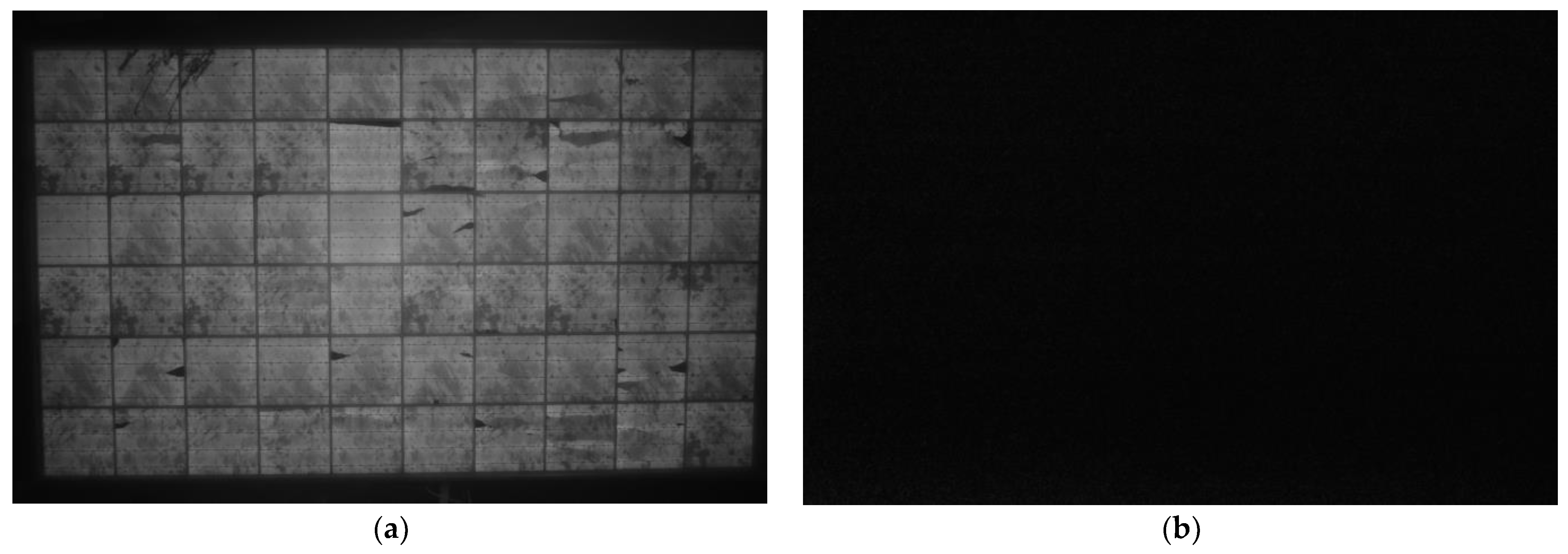
2.1. EL Imaging and Inspection Procedure

EL imaging is a non-destructive testing method that allows for the detection of defects and other issues in solar PV modules. In contrast to EL imaging, thermal imaging generally requires less stringent surface cleaning of the solar PV modules. EL imaging is highly sensitive to surface conditions and requires a clean module surface to accurately capture the luminescent signals emitted by the cells. Any dirt, dust, or debris can significantly interfere with the quality of EL images, necessitating thorough cleaning of the PV modules prior to imaging. Thermal imaging, on the other hand, is less susceptible to surface contaminants. This technique relies on detecting infrared radiation, which is emitted as heat from the modules and can penetrate minor surface contaminants more effectively than the luminescent light used in EL imaging. While a clean surface can enhance the accuracy of thermal images, the presence of moderate levels of dirt or debris on the module surface does not usually impede the effectiveness of thermal imaging to the same extent as it does in EL imaging. Therefore, while both EL and thermal imaging benefit from clean module surfaces, the necessity and frequency of cleaning are considerably higher for EL imaging due to its greater sensitivity to surface conditions. EL imaging works by applying an electrical bias to the solar PV module, which causes the cells to emit light in response to the applied voltage. The EL imaging procedure typically involves the following steps:
  • Preparation of the solar PV module: Before EL imaging can be conducted, the solar PV module must be prepared. This involves cleaning the module and removing any debris or shading materials that may interfere with the imaging process;
  • Application of electrical bias: An electrical bias is applied to the solar PV module, which causes the cells to emit light in response to the applied voltage. The electrical bias is typically applied using a specialized EL camera and/or other test equipment;
  • Imaging: The emitted light is captured by a camera, which produces an EL image of the solar PV module. The resulting image reveals any defects and/or issues in the cells, including cracks, dead cells, and other issues that may affect the performance of the module.
In this work, a Brightspot Automation EL camera which uses a high-resolution, low-light sensor to capture the EL image of the solar PV module was deployed. The camera is typically used in combination with specialized EL imaging software that can analyze the resulting images and identify any defects or issues in the cells. In addition to its imaging capabilities, the Brightspot Automation EL camera also features a rugged, durable design that is built to withstand the demands of field use. The camera is compact and lightweight, making it easy to transport and use in a variety of settings.
This specialized camera kit features a digital camera with an infrared filter removed, allowing for detection of light at a peak wavelength of 1150 nm. The camera is equipped with an 18–55 mm lens, providing flexibility in capturing images of various sizes and configurations of PV modules. To enhance the sensitivity of the EL output, the PV modules were tested under 90% short circuit conditions. It is worth noting that the short circuit conditions can also be set to 100% or a maximum of 110%. The high sensitivity of the EL output allowed for the detection of even small defects or issues in the cells. To prevent background light from affecting the quality of the EL images, all testing was conducted at night. This is because EL imaging relies on the detection of light emitted by the cells in response to an applied electrical bias. Any interference from background light can affect the accuracy and reliability of the EL images.
Figure 1 presents the EL image results of a PV module tested under two distinct solar irradiance conditions, Figure 1a depicts the nighttime condition, while Figure 1b displays the module’s response under daylight with solar irradiance equivalent to 215 W/m2. It is evident from the results that EL imaging is incapable of detecting the image when illuminated by the sun, which is currently true for all available EL imaging systems on the solar industry market. Thus, the proposed solution of developing an optical filter for the EL camera holds immense market potential and is significant for the research community.

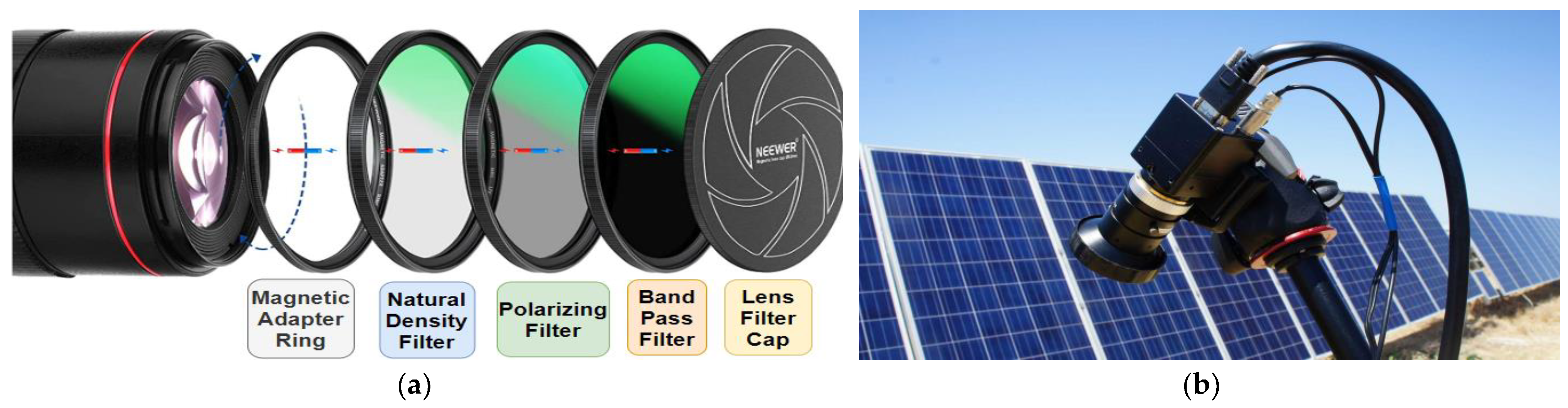
2.2. Optical Filter Design

To perform EL imaging of solar PV modules in daylight conditions, a specialized optical filter can be used to block out unwanted light and enhance the sensitivity of the EL signal. One example of such a filter is a bandpass filter with a narrow bandwidth in the near-infrared region, specifically designed to capture EL emissions from PV modules. This filter can be combined with a neutral density filter to reduce background light and improve the signal-to-noise ratio of the EL signal. The bandpass filter works by allowing only a narrow range of wavelengths to pass through to the sensor [18], specifically targeting the wavelengths emitted by the EL process in the PV cells. This greatly enhances the sensitivity of the EL signal, allowing for detection of even small defects or issues in the cells.
The neutral density filter [19,20], on the other hand, works by reducing the overall amount of light that reaches the sensor, helping to eliminate unwanted background light that can interfere with the EL signal. By reducing the amount of background light, the signal-to-noise ratio of the EL signal is significantly improved, leading to clearer and more accurate imaging of the PV cells. By combining these specialized filters with the EL camera, it is possible to perform high-quality EL imaging of solar PV modules during daytime (solar irradiance > 300 W/m2). This can provide valuable insights into the performance and condition of the cells, allowing for early detection and remediation of any issues that may arise.
The incorporation of a neutral density filter in our optical filter design for EL imaging serves a crucial purpose that extends beyond what can be achieved by simply reducing exposure time or gain. The neutral density filter uniformly attenuates the intensity of all wavelengths of light entering the camera, which is particularly important when dealing with high-intensity daylight conditions that can cause overexposure of the EL signal. While reducing exposure time or gain can indeed prevent saturation, these adjustments alone are insufficient for several reasons:
  • Dynamic range preservation: Lowering exposure time can limit the dynamic range of the camera sensor. The neutral density filter allows us to maintain a longer exposure, which is beneficial for capturing the full dynamic range of the EL signal, especially when documenting subtle defects or variations in the solar cells that could be lost with a shorter exposure;
  • Signal-to-noise ratio: Gain adjustments affect the signal-to-noise ratio (SNR). Reducing gain to prevent saturation can also diminish the EL signal, potentially increasing the relative amount of noise in the image. The neutral density filter enables therefore to keep a lower gain setting, optimizing the SNR of the EL signal;
  • Shutter speed and motion blur: Adjusting the shutter speed affects motion blur, which is a critical factor when imaging moving objects or when the camera is mounted on a moving platform such as a UAV. Hence, the neutral density filter allows for the use of optimal shutter speeds that minimize motion blur while still avoiding saturation;
  • Depth of field: The creative manipulation of depth of field in photography often involves the use of neutral density filters in conjunction with longer exposure times. This combination allows photographers to exercise precise control over the focal plane in their images. For example, when photographing a solar panel, longer exposure times facilitated by neutral density filters can be strategically employed to ensure a specific plane of the panel is captured in sharp focus while intentionally softening the focus in other areas of the composition. This technique enables photographers to achieve visually striking results by adjusting the amount of light reaching the camera’s sensor over an extended duration;
  • Consistent exposure technique: The variability of solar irradiance throughout the day can complicate the use of exposure time and gain adjustments as the sole methods for preventing saturation. A neutral density filter provides a consistent method to control light intensity. This is particularly advantageous when conducting serial inspections over time. Furthermore, the use of a neutral density filter allows for manual adjustment of its optical density to adapt to changing solar irradiance conditions during extended observations.
A bandpass filter has been designed with a center wavelength of 1150 nm and a bandwidth of 20 nm, and a neutral density filter with a transmission of 10% across the visible and near-infrared range, as shown in Figure 2a. The transmission of the bandpass filter using a transfer matrix that includes alternating layers of high and low refractive index materials, is optimized to achieve the desired spectral characteristics. The transmission of the neutral density filter using a transfer matrix that includes a thin layer of a material with a high extinction coefficient, using carbon, was also modelled and proved useful especially in terms of the practicality and application when used with different PV modules inspection, for example, if the EL is used to capture bifacial PV modules with coating materials which will result in different light emissions as compared with monofacial without coating materials.
To combine the two filters, the transfer matrices were cascaded and the resulting transmission and reflection properties of the combined filter using the transfer matrix formalism (this is available in Appendix A) were calculated. The resulting transmission would depend on the specific design parameters of each filter (wavelength of 1150 nm with bandwidth of 20 nm, and 10% transmission for the neutral density filter), as well as the angle of incidence (0 to 180 degrees) and polarization of the incident light (0 to 180 degrees). This gives the widest possible dimension for the inspection for the EL camera. The physical camera is shown in Figure 2b.
A polarizing filter was also used in the lens to control the amount and direction of polarized light that enters the natural density filter. It is used to reduce glare and reflections, improve color saturation, and enhance contrast in outdoor EL imagining, where there is a lot of unpolarized light. A magnetic adapter ring is also included for attaching filters or lens attachments to a camera lens. This type of adapter ring is designed to attach magnetically to the front of the camera lens, allowing to quickly and easily attachment or removal of filters or other accessories without having to screw them on or off. Additionally, magnetic adapter rings are less likely to cause damage to the camera lens than screw-on filters, which can sometimes get stuck or cause wear and tear on the lens threads over time. Magnetic adapters can also provide a more secure fit than some types of screw-on filters, which can be prone to slipping or loosening over time.
The optical filter’s angular response has been empirically characterized to validate our simulation results, using a light source mounted on a goniometer. This setup allowed for precise control over the angle of incidence, enabling accurate measurement of the filter’s transmission and reflection properties across a range of angles. The experimental data presented in Figure 3 supplements our simulations, providing tangible evidence of the filter’s performance. The transmission plot in Figure 3a exhibits distinct peaks around 60 and 110 degrees, which align with the expected behavior due to thin-film interference. This phenomenon arises from light reflecting off the alternating layers of differing refractive indices within the bandpass filter. Constructive interference occurs at specific angles of incidence, enhancing the filter’s transmission, while destructive interference at other angles leads to a significant reduction, corroborating the simulation results.
The empirical measurements further affirm that the transmission nears zero for most angles outside the peaks, as shown in Figure 3a. This behavior is inherent to the design of the filter, which has been optimized for peak transmission at the center wavelength of 1150 nm with a bandwidth of 20 nm, a range specifically chosen for the EL imaging of solar panels.
Reflectance measurements, shown in Figure 3b, reveal the complementary nature of the filter’s response. At angles where transmission peaks, reflectance reaches its minima, and vice versa. Notably, the experimental data demonstrates that the optimal angles for imaging—where reflectance is minimal, and transmission is maximized—are indeed between 25 to 50 degrees and 125 to 150 degrees. These findings are instrumental in confirming that the filter structure is finely tuned for EL imaging tasks.
In conclusion, the experimental validation supports the filter’s design criteria and operational efficacy for specialized EL imaging. The observed peak transmission angles and minimized reflection bands, as depicted in the experimental data, reinforce the suitability of this filter for obtaining high-quality EL images of solar panels. This validation process underscores the importance of the filter’s structural design, which considers the thickness and refractive indices of the individual layers, ensuring optimal imaging performance and clarity.

2.3. Image Processing and Signal-Noise Ratio (SNR) Metric

In the assessment of the new EL imaging system, the signal-to-noise ratio (SNR) serves as a quantitative metric for signal quality as opposed to subjective image quality evaluations. SNR was calculated for all captured images utilizing the S N R K a r i metric, initially proposed by [21]. The SNRKari is estimated using (1)–(3).
N ¯ = | x i , 1 μ 1 | N 1 + | x i , 2 μ 2 | N 2 ,
S ¯ = μ 1 μ 2 ,
S N R K a r i = { p | S p ¯ | S p ¯ p S p ¯ N p ¯ ,   i f p S p ¯ 0 .
The noise level for the time series of a signal pixel is calculated using (1), and the signal level in (2), where N 1 and N2 are the number of samples in each subsample set μ 1 and μ 2 . In (1), the numerals ‘1’ and ‘2’ distinguish between two separate images captured in the field for each pixel of the EL imaging system. Specifically, these images are part of a dual-imaging protocol designed to enhance the robustness and reliability of the signal analysis. The noise calculation is made for every pixel time-series, p , in an image stack and combined as shown in (3), where a weighting scheme is used to mainly capture the SNR level primary form pixel with detectable signal. Including both positive and negative values of S decreases contributions from areas without signal, as the random offsets cancel out. This methodology enables the detection of signal presence and its relative quality without reliance on image cropping. A threshold of S N R K a r i 1 is indicative of an adequate signal for subsequent image analysis [22]. High-quality images, particularly challenging to obtain in outdoor EL testing, are defined by S N R K a r i > 4 . Typically, outdoor EL images yield S N R K a r i values ranging from 1.5 to 2.5 [23]. Conversely, S N R K a r i values below 1 are associated with poor image quality.

3. Results

In this section, results are presented for the newly developed optical filter design for the daylight EL imaging system. The results comprise various experimentations, including EL camera with and without a polarization filter, testing of different types and configurations of PV modules (monofacial and bifacial), and the EL results under varying irradiance conditions.

3.1. Daylight Outdoor EL Test with and without Polization Filter

Figure 4 illustrates the real-life image of an EL for a PV module under outdoor conditions, with a solar irradiance of 612 W/m2, and the PV module biased at its open circuit voltage (22.5 V) and under its short circuit current (5.2 A). The image comprises two parts, which reveal the significance of using a polarization filter when capturing the EL emissions of the solar panel. In Figure 4a, the camera was operating without a polarization filter, resulting in a less clear and accurate representation of the solar panel’s cracks and/or defects. The intensity of the EL emissions is not captured, which hampers the ability to detect cracks and defects, leading to incomplete information. Figure 4b shows an image that includes the polarization filter, providing a clearer view of the EL intensity and a better distribution of the cracks and even the crack sizes. Using the polarization filter improves the accuracy of the image and enables the detection of defects in the solar panel more efficiently. The polarization filter helps to minimize the unwanted reflections and glare that often obscure the EL image when taking photos of PV modules. This, in turn, leads to a more precise detection of defects and an accurate assessment of the overall health of the solar panel.

3.2. Daylight Outdoor EL Inspection with Different PV Modules and Configruations

This section showcases the effectiveness of the developed optical filter in testing PV modules under different sun illuminations and at various angles. The EL image of the PV module was captured at different angles of incidence, i.e., the angle between the EL camera and the PV module, as shown in Figure 5. In this context, 0 degrees indicates that the camera’s optical axis is perpendicular to the plane of the PV module, while positive and negative angles indicate that the camera is tilted with respect to this perpendicular line.
Figure 5a shows that at an angle of incidence of 55 degrees, where the camera is significantly tilted, no EL output is detectable. This observation is consistent with our filter’s transmission characteristics, which predict minimal transmission at this high angle, as indicated in prior research findings [24,25]. Conversely, Figure 5b through Figure 5d demonstrate effective EL detection at +45, −30, and 0 degrees. The designation of +45 degrees corresponds to the camera being tilted 45 degrees above the plane of the module, −30 degrees denotes a 30-degree tilt below the plane, and 0 degrees represents an orientation where the camera’s optical axis is aligned perpendicularly to the module’s plane, ensuring maximum EL signal detection. Moreover, these high-quality EL images were captured with solar irradiance ranging from >500 W/m2, indicating that the optical filter is robust enough to handle varying intensities of sunlight.
There is no discernible EL output when the angle is set to 55 degrees, Figure 5a, reflected in the S N R K a r i value of 0, indicating no EL signal was detected above the noise level. However, in the subsequent images, Figure 5b–d, the S N R K a r i values are all above 2. This consistent S N R K a r i performance is indicative of high-quality EL imaging output. These values substantiate the capability of the EL imaging system to produce clear and discernible images in outdoor conditions, with S N R K a r i > 2 demonstrating a robust signal that is well above the noise level, hence ensuring the reliability of the defect detection and the overall quality assessment of the PV modules under varying observational angles.
Considering now the impact of sun illumination on the output EL image quality. After testing the EL camera at different angles, images were captured for the same PV module at three different sun illuminations: low (70 W/m2), medium (445 W/m2), and high (783 W/m2), as shown in Figure 6. The results indicate that the output EL image is not as clear when captured under low sun intensity compared to medium-to-high sun intensity levels. The main reason for this is the echo of the bandpass filter and the natural density filter. Increasing the bandwidth of the filter design from 20 nm to 60–80 nm could improve this issue. However, this change would also affect the quality of the image captured under medium-to-high sun intensity.
The primary purpose of the filter in our EL imaging system is to enhance the signal-to-background ratio by suppressing solar background illumination, thereby improving the contrast between the PV cells and their surroundings. The EL signal itself is indeed proportional to the electrical bias applied to the PV modules, not the solar irradiance. The electrical bias generates the luminescence captured in EL images, while the solar irradiance primarily contributes to the background noise in the absence of a filter. To achieve high-quality EL images in the presence of strong sunlight (>300 W/m2), as presented in Figure 6, the optical filter design must strategically limit the bandwidth to allow only the desired EL signal wavelengths while blocking out the majority of the solar spectrum. This is a delicate balance that ensures the filter’s bandwidth is narrow enough to effectively suppress the background but broad enough to transmit the EL signal without significant attenuation. In addition, we meticulously adhered to a standardized testing protocol where the bias of the PV modules remained unaltered, therefore, we can test the quality of our newly proposed EL system. Specifically, we maintained the biasing voltage of all modules at a constant 110% of their open circuit voltage.
Adjusting the neutral density filter’s optical density, as well as tuning the camera’s gain and exposure time, are indeed viable methods for enhancing the EL signal. These adjustments can compensate for the varying intensity levels of sunlight by reducing the camera’s sensitivity to unwanted light, thus further improving the contrast and visibility of defects such as cracks within the PV cells.
The approach we advocate in this work provides a degree of flexibility; by altering the camera settings and neutral density filter’s optical density, we can adapt to different levels of sun illumination while maintaining image quality. For low irradiance conditions, we can afford a slightly broader filter bandwidth, as the background light is less intense. Conversely, in bright conditions, a narrower bandwidth is preferable, accompanied by appropriate adjustments to the camera settings to optimize the EL signal and maintain high contrast and resolution in the captured images.
The developed outdoor EL camera stands out for its ability to adeptly detect EL emissions from both monofacial and bifacial photovoltaic panels. Monofacial panels are designed to absorb solar radiation on a single surface, whereas bifacial panels can capture solar energy from both the anterior and posterior facets. To demonstrate this feature, EL emissions from both the front and back surfaces of a bifacial PV module are captured. Figure 7a showcases the EL emission under a sun illumination level of 550 W/m2 from the front surface, while Figure 7b displays the corresponding emission from the back surface. These images underscore the camera’s comprehensive detection capabilities under real-world solar conditions for bifacial PV modules.
EL detection technology can be applied not only to individual PV modules but also to arrays of PV modules that are connected in series or parallel. In Figure 8, the ability of the outdoor EL camera to detect EL images of two series-connected PV modules while maintaining high image quality and resolution is illustrated. The camera can capture high-resolution images of the EL output from each individual cell within the modules, providing a comprehensive evaluation of the performance of the entire array.
To achieve this, the actual voltage biasing of the modules was set at 110% of their open circuit voltage, which was around 50 V. The short circuit current was measured at 5.5 A. This voltage biasing allowed capture of the maximum EL output from the cells within the modules. The high-quality EL images obtained from the array of PV modules provides valuable information on the overall health and performance of the modules, allowing for more efficient maintenance and troubleshooting.

4. Comparative Analysis

The newly developed EL imaging system has been evaluated through a comparative analysis with the findings reported in [26], where daylight EL images of PV modules were captured under high solar illumination conditions, specifically above 500 W/m2. Our analysis indicates a marked improvement in the clarity and detail of the EL images obtained with our system, surpassing the results presented in [26]. The images from our EL system, exemplified in Figure 9b, effectively highlight the PV module’s busbars and critically, allow for the precise localization and characterization of defects at the cellular level—capabilities that are less pronounced in the comparative images from [26], as shown in Figure 9a. This advancement in image quality is a significant stride forward, underpinning an evolution in resolution and diagnostic capabilities.
In addition to qualitative comparisons, a quantitative analysis has been employed to substantiate the superior performance of our EL imaging system. This was achieved by evaluating established metrics such as the contrast ratio and the S N R K a r i . A direct comparison of S N R K a r i values reveals that our system, with S N R K a r i = 2.33 , outperforms the system in [26], which reported S N R K a r i = 1.75 . This was achieved using the same PV module technology comprising 60-cell polycrystalline silicon PV, operating under approximately the same irradiance level. This quantitative data supports the visual analysis, confirming the system’s capacity to deliver higher-quality images under substantial solar irradiance. The improved detail captured in the images significantly enhances the detection, sizing, and classification of cell-level defects. Such precision is invaluable for conducting thorough diagnostics and ensuring the efficient upkeep of PV modules, ultimately reinforcing the performance and reliability of solar photovoltaic technologies.
The daytime EL solution presented in this work has an additional capability where the bandpass filter can be easily changed with different bandwidth filters. This allows the detection of EL signals even at very low irradiance levels. To demonstrate this feature, EL images have been included using different bandpass filters (with bandwidths of 20 nm, 50 nm, and 100 nm) under an irradiance intensity of only 25 W/m2 illustrated in Figure 10. This showcases the simplicity of the design and highlights the wider range of applications for this EL camera solution.
The versatility of this daytime EL imaging system is further accentuated by its modular filter design, which supports quick interchangeability of bandpass filters of varying bandwidths. This adaptability extends the system’s functionality to accurately detect EL signals under a spectrum of light conditions, including extremely low irradiance levels. Figure 10 exemplifies this capability, where a trio of EL images are presented, each obtained with a different bandpass filter at bandwidths of 20 nm, 50 nm, and 100 nm, all under the subtle illumination of merely 25 W/m2. The images serve not only as a testament to the operational flexibility of the camera system but also as a proof of concept for its applicability in low-light scenarios. The potential for application is vast, ranging from early morning to late evening inspections, and under various weather conditions, thus opening new avenues for continuous monitoring and assessment of PV modules.
Furthermore, the sequence of images showcases the impact of varying bandpass filter bandwidths on the S N R K a r i in EL detection under low solar irradiance. The first image with the narrowest filter bandwidth of 20 nm achieves a modest S N R K a r i of 1.41, indicating a discernible but weaker EL signal. As the filter bandwidth increases to 50 nm, there is a significant improvement in the S N R K a r i = 2.5 , suggesting that the filter’s increased range allows for a stronger EL signal while still suppressing background noise effectively. The final image, with a 100 nm filter bandwidth, records the highest S N R K a r i = 2.31 , demonstrating the clearest EL signal among the set. This progression confirms that a broader filter bandwidth can enhance EL signal detection, provided that the bandwidth is carefully chosen to maintain a high signal-to-background ratio, even in conditions of low solar irradiance.

5. Conclusions

In conclusion, this study presents a significant leap in EL imaging technology for solar PV modules. Through innovative design and rigorous testing, the new system has successfully been demonstrated on an outdoor EL imaging system that outperforms existing methods, particularly under high solar irradiance conditions. The system not only improves the clarity and intensity of EL images but also provides the versatility needed to assess both monofacial and bifacial modules with unprecedented precision. The robustness of the proposed daylight EL system is evidenced by its ability to detect defects and assess the health of PV modules under a variety of lighting conditions, a feat not achievable with traditional EL imaging systems. The customizable bandpass filters, capable of operating at different bandwidths, extend the utility of the system to low-light conditions, broadening the scope of its application beyond the limitations of current technology.
A comparative analysis confirms that the EL images obtained with the system provide a clearer and more detailed visualization of busbars and cell-level defects, which is essential for the efficient maintenance and longevity of solar installations. The modular design of the camera system, featuring easily interchangeable filters and a polarization filter option, demonstrates both the innovation and practicality of our approach.
Looking ahead, the implications of this research are substantial. By enabling accurate and efficient field diagnostics of PV modules, the new EL imaging system stands to contribute significantly to the sustainability and optimization of solar energy resources. The potential for continuous, real-time monitoring of PV installations underlines the system’s capacity to revolutionize the industry standard for PV module inspection and maintenance. As we move towards a future where renewable energy sources are paramount, the advancement presented in this work offers a promising avenue for enhancing the reliability and performance of solar energy systems worldwide.

Author Contributions

Conceptualization, M.D.; methodology, M.D. and A.M.T.; validation, A.M.T.; data curation, M.D. and A.M.T.; writing—original draft preparation, M.D.; writing—review and editing, A.M.T. All authors have read and agreed to the published version of the manuscript.

Funding

This research received no external funding.

Institutional Review Board Statement

Not applicable.

Informed Consent Statement

Not applicable.

Data Availability Statement

The datasets generated and/or analyzed during the current study are available from the corresponding author, M.D., upon reasonable request.

Conflicts of Interest

The authors declare no conflicts of interest.

Appendix A

Python code.
import numpy as np
import matplotlib.pyplot as plt
# Define constants
c = 299792458  # Speed of light in m/s
n_air = 1.0  # Refractive index of air
# Define filter parameters
wavelength = 1150e-9  # Center wavelength in meters
bandwidth = 20e-9  # Bandwidth in meters
transmission_nd = 0.1  # Transmission of the neutral density filter
# Define layer parameters for bandpass filter
n_low = 1.0  # Refractive index of low-index material
n_high = 2.0  # Refractive index of high-index material
thickness = wavelength/4  # Quarter wavelength thickness
# Calculate transfer matrices for bandpass filter
k = 2 * np.pi/wavelength  # Wave vector
delta = 2 * np.pi * thickness * (n_high - n_low)/wavelength  # Phase difference
T_bandpass = np.array([[np.cos(delta), 1j * np.sin(delta)/(n_low * np.sin(np.arccos(np.cos(delta))))],
[1j * n_low * np.sin(np.arccos(np.cos(delta)))/np.sin(delta), np.cos(delta)]])
# Define layer parameters for neutral density filter
n_extinct = 3.0 - 1j *  10  # Refractive index with high extinction coefficient
thickness_nd = 50e-9  # Thickness of neutral density filter
# Calculate transfer matrix for neutral density filter
delta_nd = 2 * np.pi * thickness_nd * n_extinct/wavelength  # Phase difference
T_nd = np.array([[np.exp(-1j * delta_nd/2), 0],
       [0, np.exp(1j * delta_nd/2)]])
# Calculate overall transfer matrix for combined filter
T = T_bandpass @ T_nd @ T_bandpass @ T_nd @ T_bandpass
# Calculate reflection and transmission coefficients for a range of angles and polarizations
theta = np.linspace(0, np.pi, 500)
polarization = np.linspace(0, np.pi, 500)
R = np.zeros((len(theta), len(polarization)))
T = np.zeros((len(theta), len(polarization)))
for i, th in enumerate(theta):
  for j, pol in enumerate(polarization):
    kx = k * np.sin(th) * np.cos(pol)
    ky = k * np.sin(th) * np.sin(pol)
    kz = np.sqrt(n_air**2 * k**2 - kx**2 - ky**2)
    T_ij = 2 * n_air * kz/(n_air * kz + n_low**2 * kz - n_low * np.sqrt(n_low**2 * k**2 - kz**2))
    R_ij = (n_low * kz - n_air * np.sqrt(n_low**2 * k**2 - kz**2))/(n_low * kz + n_air * np.sqrt(n_low**2 * k**2 - kz**2))
    T[i, j] = np.abs(T_ij)**2
    R[i, j] = np.abs(R_ij)**2
# Plot transmission curve
plt.plot(np.rad2deg(theta), T[:, 0])
plt.xlabel(‘Angle of incidence (degrees)’)
plt.ylabel(‘Transmission’)
#plot reflection curve
plt.plot(np.rad2deg(theta), R[:, 0])
plt.ylim([0, 5])
plt.xlabel(‘Angle of incidence (degrees)’)
plt.ylabel(‘Reflection’)
plt.show()

References

  1. Kouadri-Boudjelthia, E.; Chekired, F.; Belhaouas, N.; Smara, Z.; Mehareb, F. Bubbles formation on the photovoltaic cells fingers: Visual inspection of 30-year-old modules. Sol. Energy 2021, 230, 1013–1019. [Google Scholar] [CrossRef]
  2. Hassan, S.; Dhimish, M. Dual Spin Max Pooling Convolutional Neural Network for Solar Cell Crack Detection. Sci. Rep. 2023, 13, 11099. [Google Scholar] [CrossRef] [PubMed]
  3. Li, X.; Li, W.; Yang, Q.; Yan, W.; Zomaya, A.Y. An unmanned inspection system for multiple defects detection in photovoltaic plants. IEEE J. Photovolt. 2020, 10, 568–576. [Google Scholar] [CrossRef]
  4. Schuss, C.; Fabritius, T.; Eichberger, B.; Rahkonen, T. Impacts on the output power of photovoltaics on top of electric and Hybrid Electric Vehicles. IEEE Trans. Instrum. Meas. 2020, 69, 2449–2458. [Google Scholar] [CrossRef]
  5. Cheng, C.; Liu, M.; Yi, H.; Ran, G.; Chen, H. Slow manifold analysis-based detection of hot spots in photovoltaic systems. IEEE Trans. Instrum. Meas. 2022, 71, 3516510. [Google Scholar] [CrossRef]
  6. Schuss, C.; Remes, K.; Leppanen, K.; Saarela, J.; Fabritius, T.; Eichberger, B.; Rahkonen, T. Detecting defects in photovoltaic panels with the help of synchronized thermography. IEEE Trans. Instrum. Meas. 2018, 67, 1178–1186. [Google Scholar] [CrossRef]
  7. Di Tommaso, A.; Betti, A.; Fontanelli, G.; Michelozzi, B. A multi-stage model based on yolov3 for defect detection in PV panels based on IR and visible imaging by Unmanned Aerial Vehicle. Renew. Energy 2022, 193, 941–962. [Google Scholar] [CrossRef]
  8. Vergura, S. Criticalities of the outdoor infrared inspection of photovoltaic modules by means of drones. Energies 2022, 15, 5086. [Google Scholar] [CrossRef]
  9. Nooralishahi, P.; Ibarra-Castanedo, C.; Deane, S.; López, F.; Pant, S.; Genest, M.; Avdelidis, N.P.; Maldague, X.P. Drone-based non-destructive inspection of industrial sites: A review and case studies. Drones 2021, 5, 106. [Google Scholar] [CrossRef]
  10. Masita, K.; Hasan, A.; Shongwe, T. 75MW AC PV module field anomaly detection using drone-based IR orthogonal images with RES-CNN3 detector. IEEE Access 2022, 10, 83711–83722. [Google Scholar] [CrossRef]
  11. Høiaas, I.; Grujic, K.; Imenes, A.G.; Burud, I.; Olsen, E.; Belbachir, N. Inspection and condition monitoring of large-scale photovoltaic power plants: A Review of Imaging Technologies. Renew. Sustain. Energy Rev. 2022, 161, 112353. [Google Scholar] [CrossRef]
  12. Morando, L.; Recchiuto, C.T.; Calla, J.; Scuteri, P.; Sgorbissa, A. Thermal and visual tracking of photovoltaic plants for autonomous UAV inspection. Drones 2022, 6, 347. [Google Scholar] [CrossRef]
  13. Dhimish, M.; Badran, G. Recovery of photovoltaic potential-induced degradation utilizing automatic indirect voltage source. IEEE Trans. Instrum. Meas. 2022, 71, 2000209. [Google Scholar] [CrossRef]
  14. Pratt, L.; Govender, D.; Klein, R. Defect detection and quantification in electroluminescence images of solar PV modules using U-net Semantic segmentation. Renew. Energy 2021, 178, 1211–1222. [Google Scholar] [CrossRef]
  15. Dhimish, M.; Badran, G. Investigating defects and annual degradation in UK solar PV installations through thermographic and electroluminescent surveys. NPJ Mater. Degrad. 2023, 7, 14. [Google Scholar] [CrossRef]
  16. Dhimish, M.; Holmes, V. Solar cells micro crack detection technique using state-of-the-art electroluminescence imaging. J. Sci. Adv. Mater. Devices 2019, 4, 499–508. [Google Scholar] [CrossRef]
  17. Pratt, L.; Mattheus, J.; Klein, R. A benchmark dataset for defect detection and classification in electroluminescence images of PV modules using semantic segmentation. Syst. Soft Comput. 2023, 5, 200048. [Google Scholar] [CrossRef]
  18. Lv, X.; Ako, R.T.; Bhaskaran, M.; Sriram, S.; Fumeaux, C.; Withayachumnankul, W. Frequency-selective-surface-based mechanically reconfigurable terahertz bandpass filter. IEEE Trans. Terahertz Sci. Technol. 2022, 12, 257–266. [Google Scholar] [CrossRef]
  19. Nelfyenny; Achmadi, A.; Prihhapso, Y.; Farhania, W.; Suryani, D.; Zaini, H. The effect of glass neutral density filter on illuminance measurement error. J. Phys. Conf. Ser. 2021, 1918, 022028. [Google Scholar] [CrossRef]
  20. Degert, J.; Tondusson, M.; Freysz, V.; Abraham, E.; Kumar, S.; Freysz, E. Ultrafast, broadband and tunable terahertz reflector and Neutral Density filter based on high resistivity silicon. Opt. Express 2022, 30, 18995. [Google Scholar] [CrossRef]
  21. dos Reis Benatto, G.A.; Santamaria, R.D.P.; Hass, T.K.; Bartholomäus, M.; Morino, L.; Poulsen, P.B.; Spataru, S.V. Daylight Electroluminescence of PV Modules in Field Installations: When Electrical Signal Modulation is Required? In Proceedings of the 8th World Conference on Photovoltaic Energy Conversion, Milan, Italy, 26–30 September 2022; pp. 735–739. [Google Scholar]
  22. dos Reis Benatto, G.A.; Mayordomo, A.A.; Hass, T.K.; Santamaria, R.D.P.; Poulsen, P.B.; Spataru, S.V. Characterizing the Performance of Daylight Filters for Electroluminescence Imaging of Crystalline Silicon PV Modules. In Proceedings of the 40th European Photovoltaic Solar Energy Conference and Exhibition, Lisbon, Portugal, 18–22 September 2023; p. 020372. [Google Scholar]
  23. Santamaria, R.D.P.; dos Reis Benatto, G.A.; Hass, T.K.; Morino, L.; Poulsen, P.B.; Spataru, S.V. Challenges of Aerial Drone Electroluminescence in Solar Photovoltaic Field Inspections. In Proceedings of the 40th European Photovoltaic Solar Energy Conference and Exhibition, Lisbon, Portugal, 18–22 September 2023; p. 020403. [Google Scholar]
  24. Vuković, M.; Høiaas, I.E.; Jakovljević, M.; Flø, A.S.; Olsen, E.; Burud, I. Outdoor photoluminescence and electroluminescence imaging of photovoltaic silicon modules in a string. AIP Conf. Proc. 2022, 2487, 030012. [Google Scholar]
  25. Terrados, C.; González-Francés, D.; Alonso, V.; González, M.A.; Jiménez, J.; Martínez, O. Comparison of Outdoor and Indoor PL and EL Images in Si Solar Cells and Panels for Defect Detection and Classification. J. Electron. Mater. 2023, 52, 5189–5198. [Google Scholar] [CrossRef]
  26. dos Reis Benatto, G.A.; Hass, T.K.; Santamaria, R.D.P.; Spataru, S.V.; Terrados, C.; González-Francés, D.; Anaya, J.; Sulca, K.; Gómez-Alonso, V.; González, M.Á.; et al. Daylight Electroluminescence Imaging Methodology Comparison. In Proceedings of the 40th European Photovoltaic Solar Energy Conference and Exhibition, Lisbon, Portugal, 18–22 September 2023; p. 020374. [Google Scholar]
Figure 1. EL image of PV module: (a) under no sun illumination (solar irradiance = 0 W/m2); (b) under sun illumination (solar irradiance = 215 W/m2). The PV module was tested under voltage biasing at its 110% open circuit condition (V = 40 V), and under its short circuit condition (I = 7.2 A).
Photonics 11 00063 g001
Figure 2. Optical filter design architecture for the EL camera: (a) Layers of the EL camera layout; (b) Physical EL camera next to PV installation.
Photonics 11 00063 g002
Figure 3. Optical filter transmission and reflection characteristics measured at a wavelength of 1150 nm: (a) optical filter transmission vs. angle of incidence in degrees; (b) optical filter reflection vs. angle of incidence in degrees.
Photonics 11 00063 g003
Figure 4. Outdoor EL image of PV modules: (a) EL camera without the polarization filter; (b) EL camera with the polarization filter. Images are taken at a solar irradiance of 612 W/m2.
Photonics 11 00063 g004
Figure 5. Outdoor EL image of PV module at different angle of incidence (the angle between the EL camera oriented towards the PV module): (a) no output can be detected when the angle is 55 degrees; (b) at +45 degrees; (c) at −30 degrees; (d) at 0 degrees.
Photonics 11 00063 g005
Figure 6. Comparative EL images of an outdoor PV module exposed to ascending sunlight irradiance, showcasing responses at 70, 445, and 783 W/m2 levels.
Photonics 11 00063 g006
Figure 7. Outdoor EL image of bifacial PV module under sun illumination of 550 W/m2: (a) front surface; (b) back surface.
Photonics 11 00063 g007
Figure 8. Outdoor EL image of two series-connected monofacial PV modules under sun illumination of 390 W/m2; The modules were connected to an external power source at 110% of open-circuit voltage (50 V) and operating at the PV modules’ short-circuit condition of 5.5 A.
Photonics 11 00063 g008
Figure 9. Comparative analysis of daytime EL detection under similar irradiance conditions using 60-cell polycrystalline silicon PV technology between the work presented in this paper and work reported in [26]: (a) results presented in [26]; (b) new EL camera system.
Photonics 11 00063 g009
Figure 10. Comparison of EL detection under different bandpass filter bandwidths and extremely low solar irradiance of 25 W/m2: (a) filter bandwidth of 20 nm; (b) filter bandwidth of 50 nm; (c) filter bandwidth of 100 nm.
Photonics 11 00063 g010
Disclaimer/Publisher’s Note: The statements, opinions and data contained in all publications are solely those of the individual author(s) and contributor(s) and not of MDPI and/or the editor(s). MDPI and/or the editor(s) disclaim responsibility for any injury to people or property resulting from any ideas, methods, instructions or products referred to in the content.

