Communication

Diode-Pumped Single-Longitudinal-Mode Pr3+:YLF Laser Based on Combined Fabry–Perot Etalons at 522.67 nm

Jilin Key Laboratory of Solid-State Laser Technology and Application, School of Physics, Changchun University of Science and Technology, Changchun 130022, China
*
Authors to whom correspondence should be addressed.
Photonics 2023, 10(9), 971; https://doi.org/10.3390/photonics10090971
Submission received: 30 June 2023 / Revised: 23 August 2023 / Accepted: 23 August 2023 / Published: 24 August 2023
(This article belongs to the Section Lasers, Light Sources and Sensors)

Abstract

:
We create a rate equation theoretical model of a continuous-wave end-pumped Pr3+:YLF SLM laser that characterizes the output properties of a single-longitudinal-mode (SLM) green laser. After inserting two Fabry–Perot (F–P) etalons with thicknesses of 0.3 mm and 0.5 mm and angles of 1.42° and 0.69° into the cavity, a single-longitudinal-mode green laser was generated. The maximum output power in single-longitudinal mode was 183 mW. The maximum absorbed pump power was 6.2 W. The corresponding linewidth is about 18 MHz. This work presents a simple method for generating a single-longitudinal-mode laser in the green spectral region, providing a practical approach for various green-laser-related applications.

1. Introduction

Single-longitudinal-mode (SLM) laser sources have a narrow linewidth and low noise, and they are widely employed in coherent optical communication, precision measurement, holography, and high-resolution spectrum [1,2,3,4]. The SLM green laser has potential applications in spectroscopic analysis as an excitation source for optical frequency standards and Doppler wind lidar [5,6]. After the doubling frequency of the green laser, it is also possible to easily create 261 nm ultraviolet lasers or other ultraviolet lasers with different wavelengths. The traditional and standard method of generating continuous-wave green SLM lasers is nonlinear frequency conversion using the double frequency or sum frequency. On the other hand, additional phases of nonlinear frequency conversion need a fine temperature-controlled nonlinear crystal, resulting in a laser system with high complexity, high cost, green noise, and low conversion efficiency [7,8]. We all know that yttrium lithium fluoride (YLF) can produce linearly polarized outputs with almost no depolarization loss. In addition, praseodymium-doped laser crystals (Pr3+) have lower phonon energy, abundant wavelengths (720, 640, 604, 522, and 479 nm) can be acquired directly, and the crystals can also greatly alleviate the laser thermal lens effect [9,10,11,12,13]. Luo et al., for example, employed a diode-pumped solid-state laser directly generating continuous-wave SLM outputs at 640 nm in 2019, achieving a maximum output power of 403 mW with a threshold of 600 mW and a slope efficiency of 26.8%. The linewidth of the emission spectrum was 150 MHz [14]. Zhang et al. developed diode-pumped single-wavelength SLM lasers at 607 nm and 604 nm in 2020. The maximum output powers were 175 mW and 91 mW, and the corresponding linewidth are 6 and 22 MHz, respectively [15]. Mu et al. developed a dual-pulse narrow linewidth laser at 639 nm with a maximum output average power of 78 mW in 2023. The laser achieves a single-longitudinal-mode operation with a linewidth of 37.5 MHz with an average output power of 23 mW [16]. Unlike the previous work, this paper establishes the rate equation containing the transmission loss of the combined F–P etalons and solves it numerically for the green continuous laser. However, no one has reported the Pr3+:YLF SLM green laser until now. To eliminate the “green problem (The conventional method of obtaining green laser by frequency doubling is often accompanied by high-frequency noise.)”, single-frequency operation is needed. There are now various techniques for realizing the SLM output of a solid-state laser, for example, ring-cavity, two Fabry–Perot etalons, birefringent filters, twisted-mode cavities, and so on [17,18,19,20]. Compared to other technologies, the Fabry–Perot (F–P) etalon has several benefits, including simple fabrication, broad bandwidth, and a large free spectral range. This approach offers the option of achieving Pr3+:YLF SLM laser output.
To the best of our knowledge, we directly obtained the visible Pr3+:YLF SLM laser at 522.67 nm in this investigation by selecting two Fabry–Perot etalons with acceptable thicknesses or an adequate free spectral range.

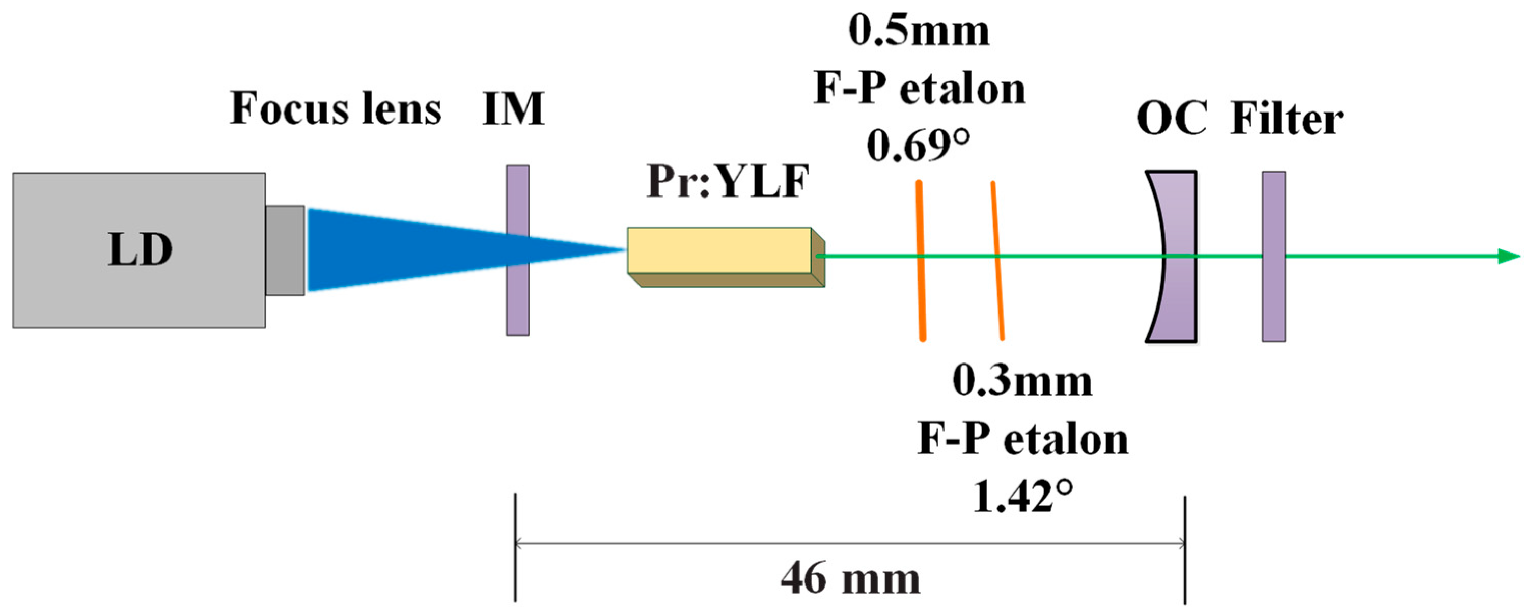
2. Experimental Setup

The Pr3+:YLF SLM laser’s schematic is observed in Figure 1. It uses a straightforward two-mirror plane-concave arrangement. An input mirror (IM), an a-cut Pr3+:YLF crystal used as the gain medium, two Fabry–Perot etalons, and an output coupler (OC) comprised the resonator’s cavity. The pump source was an InGaN diode laser with a 444 nm emission wavelength. Because the pump source uses a semiconductor laser, it will produce temperature drifts with increased output power. Its central wavelength is 441.3 nm near the threshold, and this value changes to 444.1 nm when the maximum output power is reached. A 50 mm focusing lens focused the pump beam into the laser crystal. The pump laser spot is as small as 220 μm in the crystal. The highly reflective mirror IM was coated for anti-reflection transmission at 443 nm (T > 99.5%) and a reflectivity of 99.8% at 522 nm. The OC comprised a concave mirror with a 50 mm curvature radius, a 2.5% at 522 nm transmission coating, and anti-reflection transmission at 470–490 nm and 590–650 nm (T > 99.5%) to suppress this high-gain emission. The Pr3+:YLF crystal was a-cut at 0.5% and doped at the size of 3 mm × 3 mm × 5 mm. The filter was coated for a reflectivity of 99.8% at 444 nm and had a transmittance of 99.8% at 522 nm. The temperature of the Pr3+:YLF crystal is maintained at 18 °C by mounting it on top of a copper radiator that is cooled using a water cooler and sealed with indium foil. The uncoated Fabry–Perot etalons, which were placed in the cavity to enhance SLM selection, have 0.3 and 0.5 mm thicknesses and are composed of fused silica. Fused silica material (5.5 × 10⁻⁷/K) has a lower coefficient of thermal expansion than BK7 glass material (7.1 × 10⁻⁶/K). The F–P etalons’ tilt angles are controlled by two five-dimensional optical adjustment frames. The physical cavity’s length between the input and output mirror was obtained via experimentation and theoretical calculations, and the length is roughly 46 mm.

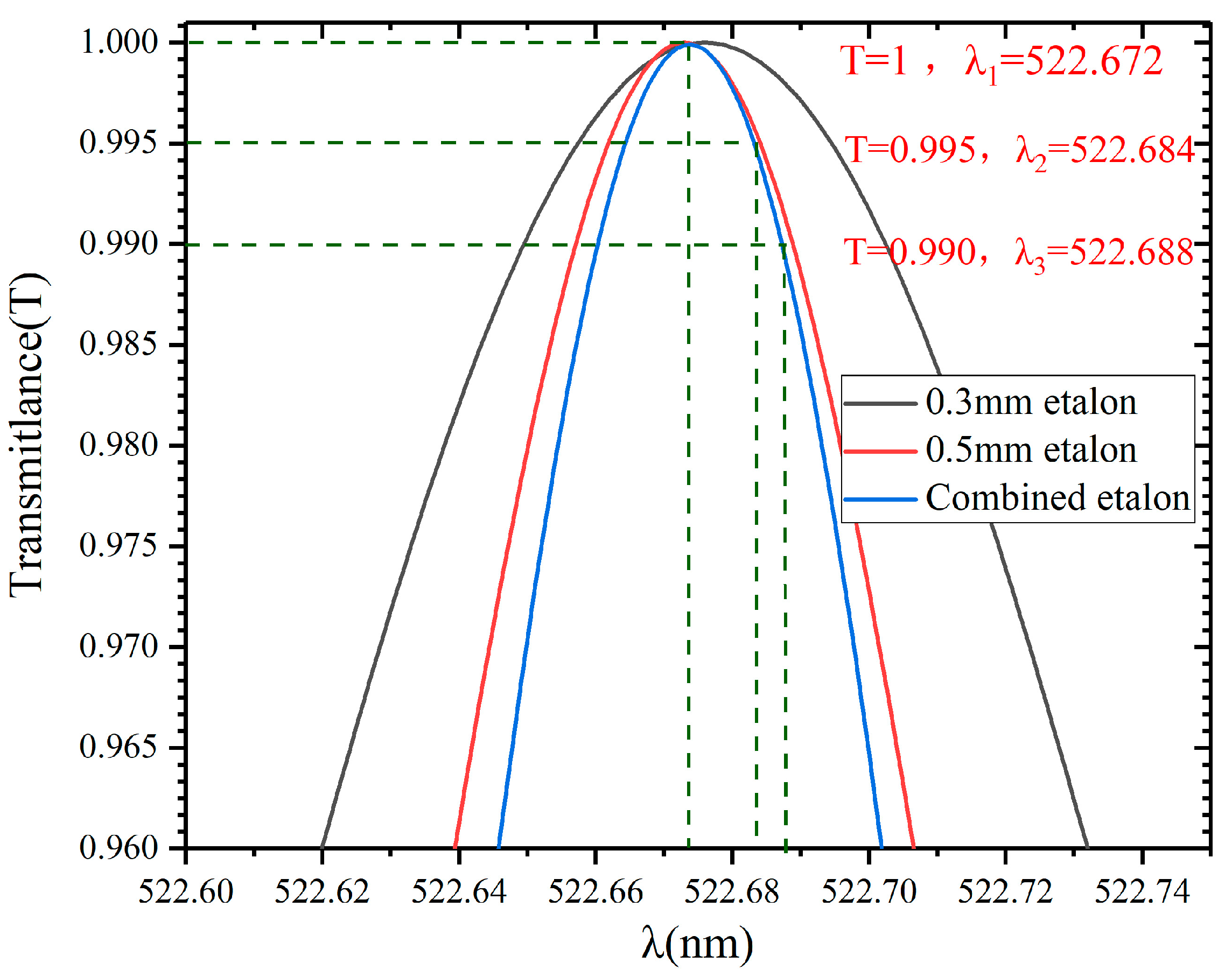
3. Experimental Principle

According to the rate equations of the four-level laser [21], the one-way total of the two F–P etalons of the four-level laser was obtained:
d N d t = R p B φ N N τ
d φ d t = B V α N 1 τ c φ
T I v = 1 1 + 4 R / 1 R 2 s i n 2 ( 2 π n d c o s θ 1 / λ )
T I I v = 1 1 + 4 R / 1 R 2 s i n 2 ( 2 π n d c o s θ 2 / λ )
τ c = L e γ c , γ = l n R l n R + T + L l o s s f p I + L l o s s f p I I
Equations (1) and (2) are the rate equations of the four-level laser. φ is the intracavity photon number of the four-level laser. N is the upper level’s inverse population. R p = P a b / h ν π ω 2 l is the pumping rate of the four-level laser. τ c is the intra-cavity photon lifetimes of the four-level laser, and V α is constant related to the mode volume. The four-level laser’s spot size and gain medium are described by the constant B = 2 σ c / π ω L e . T I v and T I I v are the transmittance functions of the etalons, R is the reflectivity of the etalon, and n and d are the refractive index and thickness of the etalon, respectively. θ is the refractive angle of the beam in the Fabry–Perot etalon. λ is the wavelength of the incident light. R and R are the reflectivity of the reflection mirror and output mirror; l n R and l n R are the losses at the total reflection mirror and output mirror, respectively. T is the dissipative loss; L l o s s f p I = 1 T I v and L l o s s f p I I = 1 T I I v are the loss of F–P etalons. The lasing threshold P t h of the 522 nm Pr3+:YLF laser, considering the F–P group effect, is represented by Equation (6).
P t h = γ π ω 2 h ν τ f η p σ
To realize the SLM laser output of a specific frequency, inserting the Fabry–Perot etalon into the cavity is a simple and effective method. The relationship of the transmittance product of two Fabry–Perot etalons is established to achieve the highest laser conversion efficiency in the SLM laser. Its key parameters are optimized to maximize the gain of the central mode. Meanwhile, other methods are suppressed. Thus, the excitation SLM is realized. The transmission function of two Fabry–Perot etalons is given:
T = T 1 T 2 = 1 1 + 4 R / 1 R 2 s i n 2 ( 2 π n d 1 c o s θ 1 / λ ) 1 1 + 4 R / 1 R 2 s i n 2 ( 2 π n d 2 c o s θ 2 / λ )
Changing the F–P etalons’ characteristics makes it possible to manipulate the transmittance of various wavelengths intentionally. Based on Equations (3) and (4), the best incidence angle ( θ 1 = 0.69 , θ 2 = 1.42 ) of the maximum transmittance of the central wavelength (522 nm) can be calculated, as shown in Figure 2.
The losses per pass at each longitudinal mode were then calculated using Equations (3), (4) and (7), as shown in Figure 3. The etalon group thus has improved capabilities in wavelength discrimination. The etalons’ angle may be changed to ensure that only one mode T λ 1 is at its transmission peak and has the maximum gain, while the neighboring T λ 2 and T λ 3 modes suffer significant losses and are suppressed.

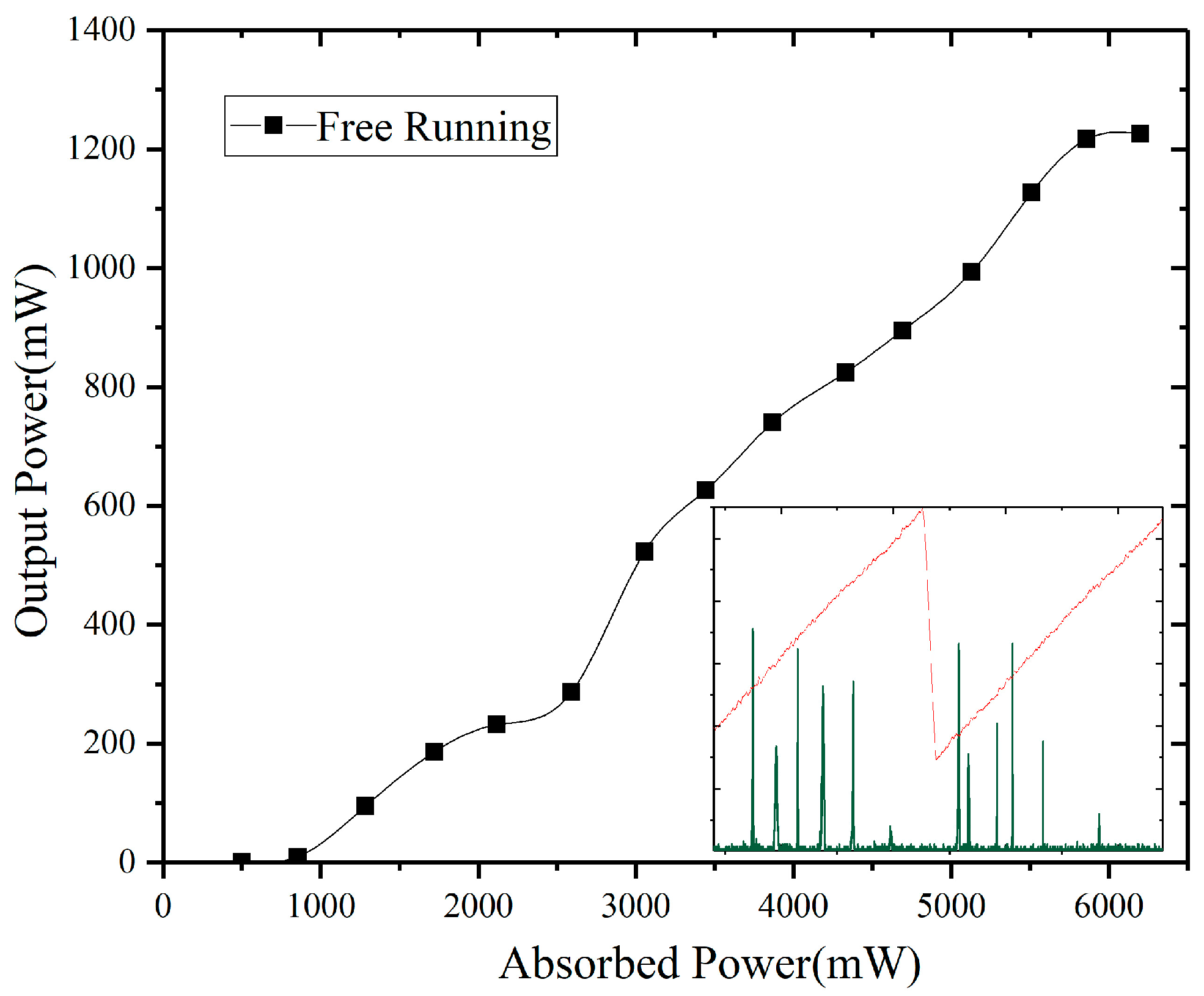
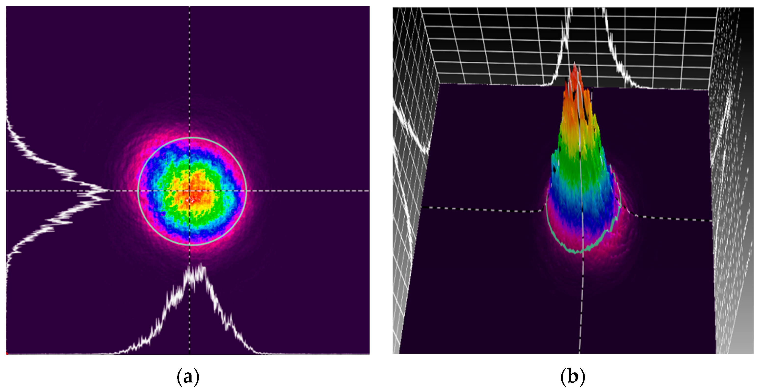
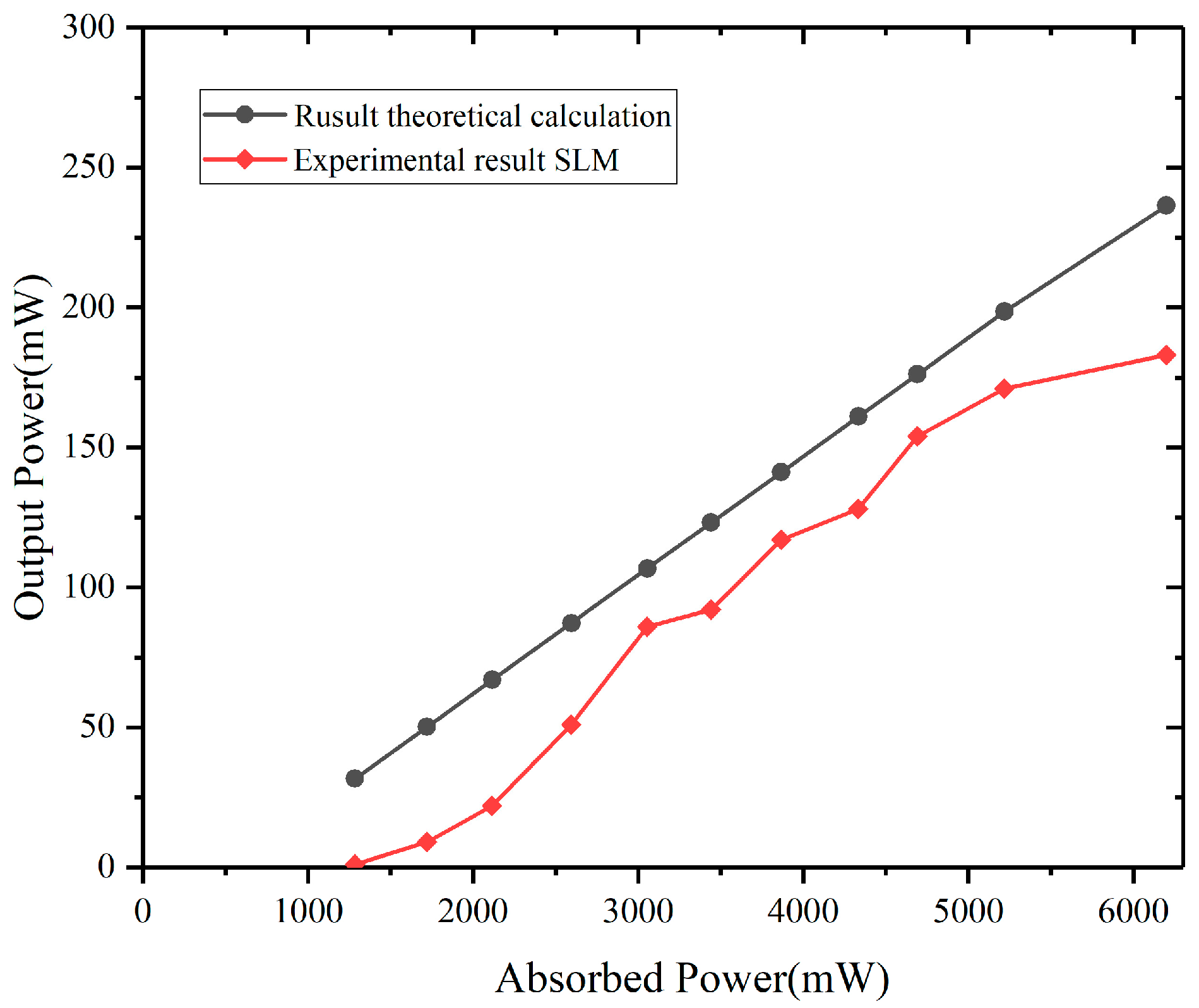
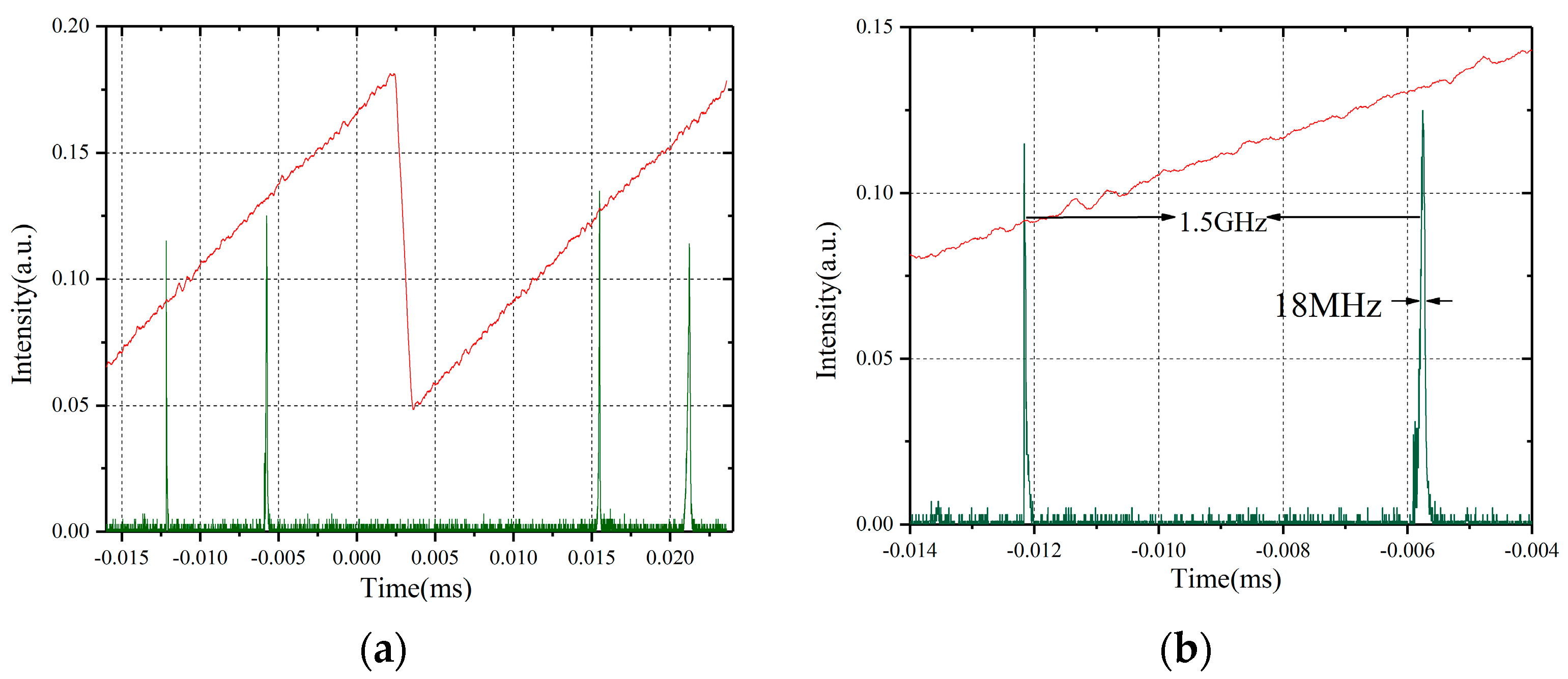
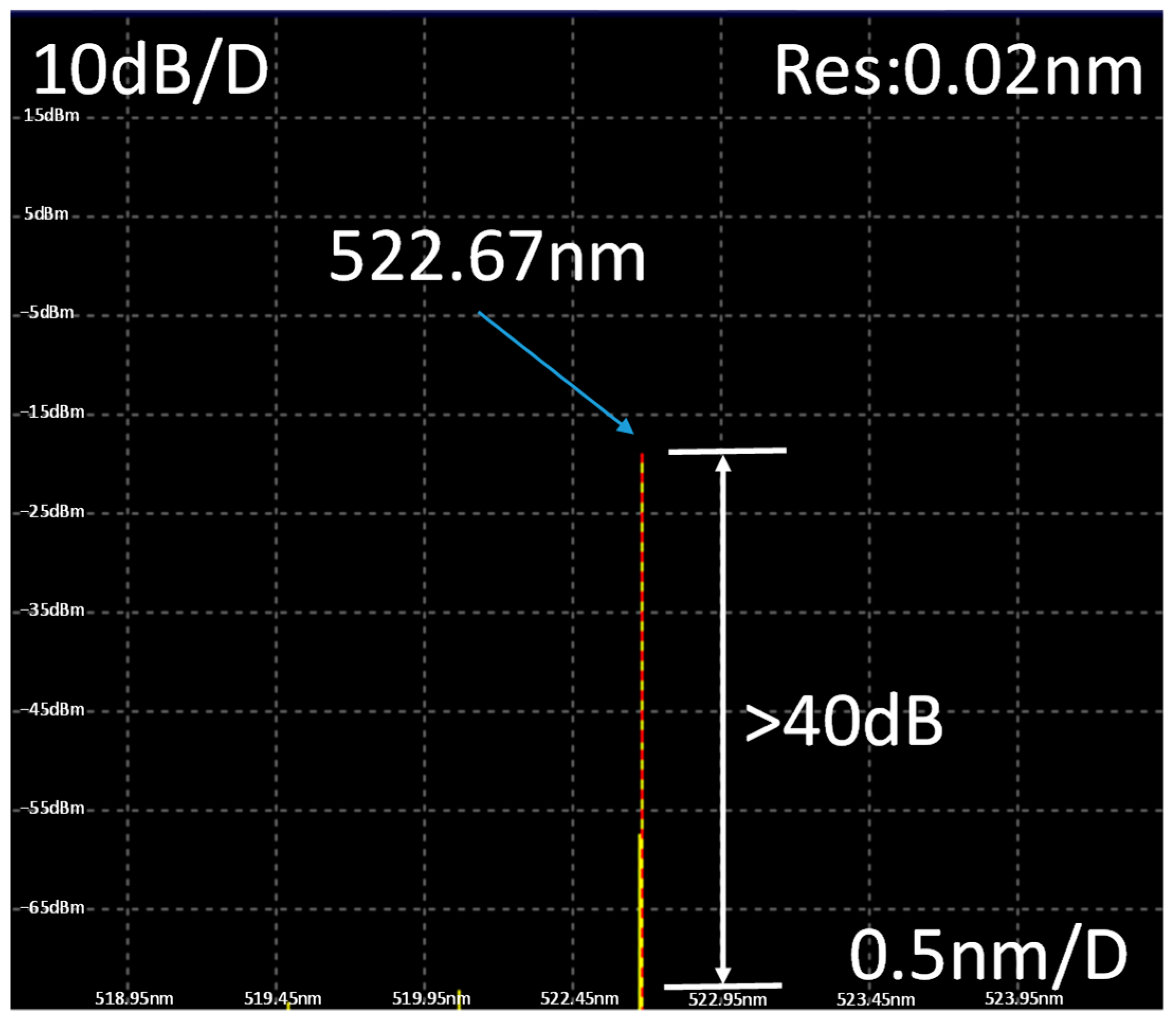
4. Experimental Results and Discussion

In the experimental procedure, we have developed a continuous-wave green laser at 522 nm with a maximum output power of 1.226 W at an absorbed power of 6.2 W, a laser threshold of roughly 1.19 W, and a slope efficiency of 19.8%. We employed a scanning F–P etalon interferometer (SA200-3B, Thorlabs) with a free spectral range of 1.5 GHz to assess the laser spectral characteristic. The red curve in the figure shows the level profile applied to the piezoelectric ceramic within the F–P interferometer. The level curve is usually a triangular wave that increases and decreases linearly over one cycle. Piezoelectric ceramics control the air gap thickness within the F–P interferometer. The air gap thickness varies, and the time it takes for the laser’s different longitudinal modes (with a resolution of 7.5 MHz) to reach the photoelectric conversion device (CCD) varies. The green curve is the received signal curve of the photoelectric conversion device. For a single-longitudinal-mode laser, only one group of two signals of similar intensity will appear in one scanning cycle. For a multi-longitudinal mode laser, there will be multiple sets of signals with different intensities in one scanning cycle. Free-running Pr3+:YLF lasers typically operate under multimode oscillations, and competition between the various models is fierce, as shown in Figure 4.
The following explanation explains the green laser’s slope efficiency [22]. The slope efficiency formula is as follows:
η s = η p η t η S t o k e s η c
where η S t o k e s = λ p / λ t is the Stokes efficiency. η p is the ratio of excited ions to absorbed pump photons, which is often taken to be one. Suppose that the overlapping efficiency of the pumping laser and the laser mode is η t = 1 and η S t o k e s = λ p λ t = 85 % . We can calculate η c = 23.3 % , according to the following:
η c = l n ( 1 T o c ) / [ l n 1 T o c + L i ]
The internal round-trip cavity losses are denoted by L i , and the output mirror’s transmission is denoted by T o c . L i = 8.3 % is calculated. This indicates that current lasers have a medium loss. We may deduce from this calculation that the green laser has the maximum Stokes efficiency. A 0.3 mm Fabry–Perot etalon is then placed within the cavity. The Pr3+:YLF laser has a reduced longitudinal model number and a maximum output power of 700 mW with a slope efficiency of 12.7%. As observed in Figure 5, how close the laser is to performing SLM operations is demonstrated.
To realize the SLM of the Pr3+:YLF laser, we used two Fabry–Perot etalons in the resonator. According to Figure 6, the theoretical value is greater than the experimental value, and both theoretical and experimental analyses’ results indicate an upward tendency. Various variables impact experimental outcomes, whereas the theoretical number represents the simulation’s idealized results. There is a 183 mW maximum output power and a 3.6% slope efficiency. Two Fabry–Perot etalon transmission and diffraction losses might be the reason for the SLM Pr3+:YLF lasers’ poorer efficiency and higher threshold. Of course, the theoretical model does not take into account the reabsorption loss specific to quasi-triple energy level lasers, which is also the main reason for the deviation. The stability of the laser power over time is also great. The laser works for about an hour, during which the output power change rate does not exceed 2%.
By setting the angle of each of the two F–P standards in the resonant cavity, it is ensured that only one of the longitudinal modes of the output laser is at peak transmission and has maximum gain. Additionally, when the F–P etalon angle is 1.42° for 0.3 mm thickness and 0.69° for 0.5 mm thickness, the single-mode wavelength output is achieved by rotating the etalon’s angle. The laser can then provide an SLM output, as observed in Figure 7a.
According to previous accounts, the waveform was a spectral Lorentzian waveform based on an approximation of the linewidth solution [23]. As shown in Figure 7b, we process them using collected data. This indicates that they are all realized by software programs. The corresponding linewidth is about 18 MHz.
As shown in Figure 8, we obtained a wavelength of 522.67 nm with respect to the green laser using a spectrum analyzer (AQ6373, Yokogawa, Tokyo, Japan). The side mode rejection ratio is more than 40 dB, as measured using the spectrum analyzer. Although its resolution of 0.02 nm is insufficient for single longitudinal mode laser linewidth measurements, it can still be used to measure the center wavelength and the side mode suppression ratio.
The SLM laser was measured using the beam profiler, and the output beam of the laser was collected and analyzed. Its two-dimensional and three-dimensional results are shown in Figure 9a,b. The center spotlight’s field intensity is high, the edge light’s field intensity is weak, and the overall spot shows a near-Gaussian distribution. Beam quality factor M2 at the maximum output power of the SLM laser is obtained using the 90/10 knife edge method. Beam quality factor M2 was calculated to be 1.39 and 1.37 in the x- and y-axes, respectively.
In addition, the stability of the emission wavelength over time is also good. Since two F–P etalons are introduced into the laser cavity, the output central wavelength will change with the inclination of F–P etalons. To ensure the stable operation of the two single-frequency lasers from the threshold to the maximum output power, we had to carefully re-adjust the angle of the standard fixtures at each output power, which resulted in a change in the center wavelength at different injection powers. Via the measurement of the spectrometer, it was found that the variation range of the central wavelength is 522.54–522.71 nm. However, it is worth noting that due to the unchanged cavity length and the control of crystal temperature, the wavelength will not have a substantial tuning amount.

5. Conclusions

We created a theoretical model of a continuous-wave end-pumped Pr3+:YLF SLM laser rate equation, and using theoretical simulations, we could describe the SLM green laser’s output characteristics. Previous theoretical studies were conducted using a double-pulse 639 nm red laser. Most laser intracavity losses come from acousto-optic Q-switched losses rather than F–P etalons’ losses. Since the pulsed laser is in a changing state, it does not solve for values such as the slope efficiency and threshold of the laser. In this paper, the solution and validation of the above parameters are obtained for continuous lasers. The current theoretical model was validated using the real-world example of the diode-end-pumped Pr3+:YLF laser based on dual Fabry–Perot etalons. We can obtain the highest SLM output power of 183 mW and the associated linewidth of 18 MHz by adjusting the angle of two F–P etalons to 1.42° and 0.69°. Compared to a traditional green laser, the SLM device’s design is straightforward and simple and represents a new technical approach to developing the green laser.

Author Contributions

Conceptualization, W.D. and H.W.; methodology, L.J.; software, L.J.; validation, W.D., C.L. and Y.D.; formal analysis, W.D.; investigation, W.D.; resources, W.D.; data curation, W.D.; writing—original draft preparation, G.J.; writing—review and editing, W.D.; visualization, W.D.; supervision, W.D.; project administration and funding acquisition, G.J. All authors have read and agreed to the published version of the manuscript.

Funding

This research was funded by the Department of Science and Technology of the Jilin Province (Grant no. 20230508138RC), the Department of Human Resources and Social Security of the Jilin Province (Grant no. 634230337004), the National Natural Science Foundation of China (Grant no. U19A2077) and the National Natural Science Foundation of China (Grant no. 61505012).

Institutional Review Board Statement

Not applicable.

Informed Consent Statement

Not applicable.

Data Availability Statement

The data presented in this study are available upon request from the corresponding author.

Acknowledgments

We are grateful for the research equipment and materials provided by the Jilin Key Laboratory of Solid-State Laser Technology and Application.

Conflicts of Interest

The authors declare no conflict of interest.

References

  1. Pan, D.; Ke, C.; Fu, S.; Liu, Y.; Liu, D.; Willner, A.E. All-optical spectral linewidth reduction of lasers for coherent optical communication. Opt. Lett. 2013, 38, 5220–5223. [Google Scholar] [CrossRef] [PubMed]
  2. Wang, R.; Xia, Y.; Grosser, H.; Wetzel, H.U.; Kaufmann, H.; Zschau, J. The 2003 Bam (SE Iran) earthquake: Precise source parameters from satellite radar interferometry. Geophys. J. R. Astron. Soc. 2010, 159, 917–922. [Google Scholar] [CrossRef]
  3. Camacho-López, S.; Damzen, M.J. Self-starting Nd:YAG holographic laser oscillator with a thermal grating. Opt. Lett. 1999, 24, 753–755. [Google Scholar] [CrossRef] [PubMed]
  4. Liu, Z.; Cai, Z.; Huang, S.; Zeng, C.; Meng, Z.; Bu, Y.; Luo, Z.; Xu, B.; Xu, H.; Ye, C.; et al. Diode-pumped Pr3+:LiYF4 continuous-wave deep red laser at 698 nm. J. Opt. Soc. Am. B 2013, 30, 302–305. [Google Scholar] [CrossRef]
  5. Okhapkin, M.V.; Skvortsov, M.N.; Belkin, A.M.; Kvashnin, N.L.; Bagayev, S.N. Tunable single-frequency diode-pumped Nd:YAG ring laser at 1064/532nm for optical frequency standard applications. Opt. Commun. 2002, 203, 359–362. [Google Scholar] [CrossRef]
  6. Yang, F.; Ye, Q.; Pan, Z.; Chen, D.; Cai, H.; Qu, R.; Yang, Z.; Zhang, Q. 100-mW linear polarization single-frequency all-fiber seed laser for coherent Doppler lidar application. Opt. Commun. 2012, 285, 149–152. [Google Scholar] [CrossRef]
  7. Sotor, J.Z.; Antończak, A.J.; Abramski, K.M. Single-longitudinal mode Nd:YVO4/YVO4/KTP green solid state laser. Opto-Electron. Rev. 2010, 18, 75–79. [Google Scholar] [CrossRef]
  8. Sotor, J.Z.; Dudzik, G.; Antonczak, A.J.; Abramski, K.M. Single-longitudinal mode, monolithic, green solid-state laser. Appl. Phys. B 2011, 103, 67–74. [Google Scholar] [CrossRef]
  9. Esterowitz, L.; Bartoli, F.J.; Allen, R.E.; Wortman, D.E.; Morrison, C.A.; Leavitt, R.P. Energy levels and line intensities of Pr3+ in LiYF4. Phys. Rev. B 1979, 19, 6442–6455. [Google Scholar] [CrossRef]
  10. Richter, A.; Heumann, E.; Huber, G.; Ostroumov, V.; Seelert, W. Power scaling of semiconductor laser pumped Praseodymium-lasers. Opt. Express 2007, 15, 5172–5178. [Google Scholar] [CrossRef]
  11. Metz, P.W.; Reichert, F.; Moglia, F.; Müller, S.; Marzahl, D.T.; Kränkel, C.; Huber, G. High-power red, orange, and green Pr3+:LiYF4 lasers. Opt. Lett. 2014, 39, 3193–3196. [Google Scholar] [CrossRef] [PubMed]
  12. Sugiyama, N.; Fujita, S.; Hara, Y.; Tanaka, H.; Kannari, F. Diode-pumped 640 nm Pr:YLF regenerative laser pulse amplifier. Opt. Lett. 2019, 44, 3370. [Google Scholar] [CrossRef] [PubMed]
  13. Tanaka, H.; Fujita, S.; Kannari, F. High-power visibly emitting Pr3+:YLF laser end pumped by single-emitter or fiber-coupled GaN blue laser diodes. Appl. Opt. 2018, 57, 5923–5928. [Google Scholar] [CrossRef] [PubMed]
  14. Luo, S.; Cai, Z.; Xu, H.; Shen, Z.; Chen, H.; Li, L.; Cao, Y. Direct oscillation at 640-nm in single longitudinal mode with a diode-pumped Pr:YLF solid-state laser. Opt. Laser Technol. 2019, 116, 112–116. [Google Scholar] [CrossRef]
  15. Zhang, Y.; Zhou, L.; Zhang, T.; Cai, Y.; Xu, B.; Xu, X.; Xu, J. Blue diode-pumped single-longitudinal-mode Pr:YLF lasers in orange spectral region. Opt. Laser Technol. 2020, 130, 106373. [Google Scholar] [CrossRef]
  16. Mu, X.S.; Jin, L.; Dong, Y.; Yu, Y.J.; Jin, G.Y. Double-pulse narrow-linewidth Pr:YLF laser with acousto-optic Q-switching and double Fabry–Perot etalon technology. Opt. Commun. 2023, 527, 128924. [Google Scholar] [CrossRef]
  17. Lu, H.; Su, J.; Zheng, Y.; Peng, K. Physical conditions of single-longitudinal-mode operation for high-power all-solid-state lasers. Opt. Lett. 2014, 39, 1117–1120. [Google Scholar] [CrossRef]
  18. Dai, T.; Wu, J.; Zhang, Z.; Ju, Y.; Yao, B.; Wang, Y. Diode-end-pumped single-longitudinal-mode Er:LuAG laser with intracavity etalons at 1.6 μm. Appl. Opt. 2015, 54, 9500–9503. [Google Scholar] [CrossRef]
  19. Chen, S.Y.; Yang, H.L.; Wang, M.J.; Zhang, X.; Jiang, J.; Meng, J.Q.; Chen, W.B. Analysis of Natural Longitudinal Mode Selection in Passively Q-Switched Lasers. Chin. J. Lasers 2016, 43, 0801006. [Google Scholar] [CrossRef]
  20. Wu, E.; Pan, H.; Zhang, S.; Zeng, H. High power single-longitudinal-mode operation in a twisted-mode-cavity laser with a c-cut Nd:GdVO4 crystal. Appl. Phys. B 2005, 80, 459–462. [Google Scholar] [CrossRef]
  21. Svelto, O. Principles of Lasers; Springer: New York, NY, USA, 2010. [Google Scholar]
  22. Luo, S.; Yan, X.; Cui, Q.; Xu, B.; Xu, H.; Cai, Z. Power scaling of blue-diode-pumped Pr:YLF lasers at 523.0, 604.1, 606.9, 639.4, 697.8 and 720.9 nm. Opt. Commun. 2016, 380, 357–360. [Google Scholar] [CrossRef]
  23. Jin, L.; Dai, W.; Yu, Y.; Dong, Y.; Jin, G. Single longitudinal mode Q-switched operation of Pr:YLF laser with pre-lase and Fabry–Perot etalon technology. Opt. Laser Technol. 2020, 129, 106294. [Google Scholar] [CrossRef]
Figure 1. Pr3+:YLF SLM laser experimental setup at 522.67 nm.
Photonics 10 00971 g001aPhotonics 10 00971 g001b
Figure 2. The variation of transmittance angle at 522 nm.
Photonics 10 00971 g002
Figure 3. The relationship between transmittance and wavelength.
Photonics 10 00971 g003
Figure 4. Free-running in the multi-longitudinal mode; output power versus absorbed power.
Photonics 10 00971 g004
Figure 5. Output power versus absorbed power for one 0.3 mm F–P etalon of the green laser with the multi-longitudinal-mode.
Photonics 10 00971 g005
Figure 6. Output characteristics of the Pr3+:YLF laser based on combined Fabry–Perot etalons.
Photonics 10 00971 g006
Figure 7. (a) F–P interferometer scanning spectrum and (b) linewidth measurement of the 522.67 nm SLM laser.
Photonics 10 00971 g007
Figure 8. Spectrum of the 522.67 nm laser measured using the spectrum analyzer.
Photonics 10 00971 g008
Figure 9. Measurement of the output beam profile of the 522.67 nm SLM laser. Beam intensity distribution in 2-D (a) and 3-D (b).
Photonics 10 00971 g009
Disclaimer/Publisher’s Note: The statements, opinions and data contained in all publications are solely those of the individual author(s) and contributor(s) and not of MDPI and/or the editor(s). MDPI and/or the editor(s) disclaim responsibility for any injury to people or property resulting from any ideas, methods, instructions or products referred to in the content.

