2.1. The Impact of CP on the AO-OFDM System
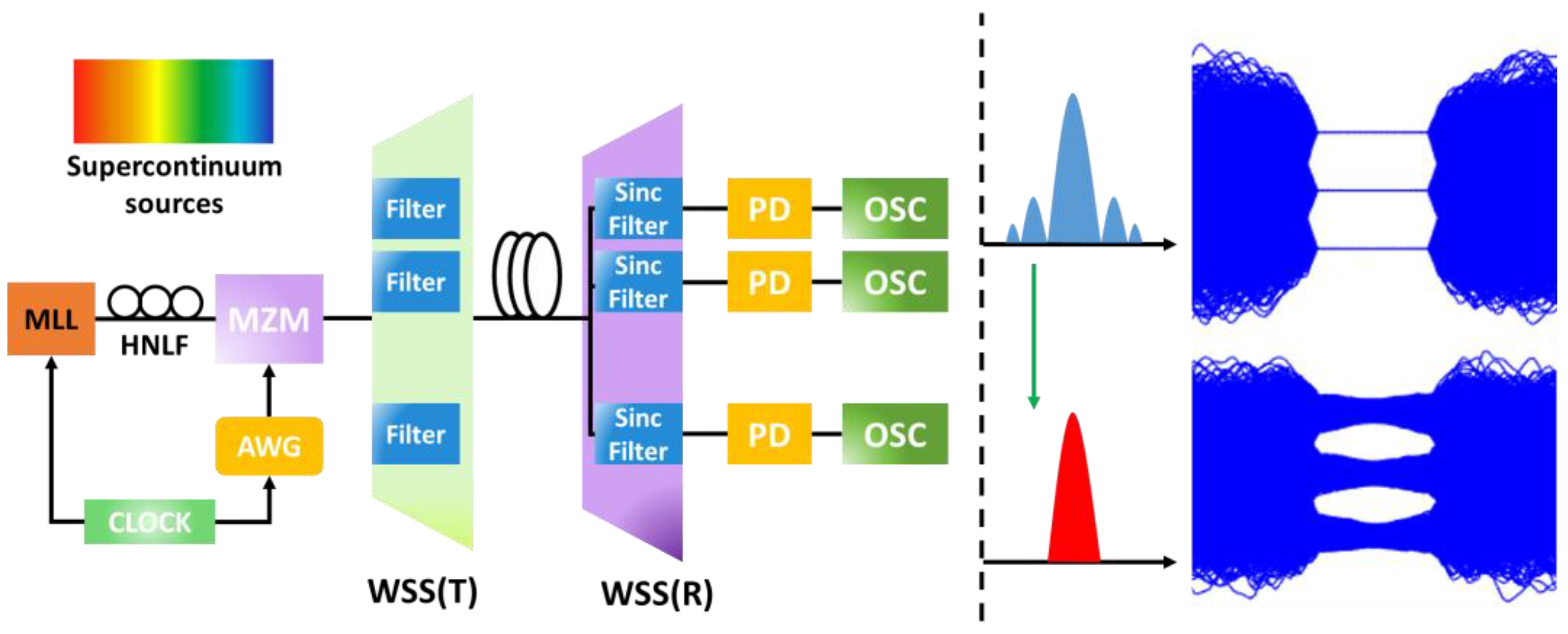
In the transmitter, the LCoS programmable WSS was used to perform Sinc-shaped filtering on a super-continuum optical source so as to generate multiple orthogonal carriers, which were further modulated to become the sub-carriers of the AO-OFDM system. These sub-carriers were multiplexed by WSS to form the complete AO-OFDM signal. Although the OFDM system with inserted CP required accurate chromatic dispersion compensation and monitoring at the receiving end, the CP could still mitigate the impact of dispersion on the AO-OFDM system, to a certain extent. We used the CP to cooperate with our proposed scheme to improve the system’s resistance to dispersion.
In order to reduce the influence of lower inter-carrier interference and component defects on the system, the insertion of CP is essential. In a traditional electrical OFDM system, the CP is inserted by adding the end of each symbol to the beginning of the next symbol and approaches functions that can be easily implemented in the AO-OFDM system [
10,
17]. In Ref. [
10], the CP was added by increasing the filter bandwidth of the filter that generated orthogonal subcarriers by supercontinuum filtering.
The signal of the AO-OFDM system with CP can be expressed as:
where
Cki is the
ith signal symbol on the kth subcarrier,
Tb is the symbol period,
fc is the center frequency of the OFDM system, and
uk(
t) and
gcp(
t) are the waveform− and pulse-shaping functions of the
kth subcarrier, respectively. The pulse-shaping function without CP is
g(
t):
where
Ts is the symbol period; the frequency domain filter functions corresponding to the two pulse-shaping functions are:
The added CP can be calculated as
, where
and
are the bandwidth of the Sinc function and symbol rate, respectively.
is the center frequency of the Sinc-shaped filter corresponding to the kth orthogonal subcarrier with the filter bandwidth of
after inserting CP.
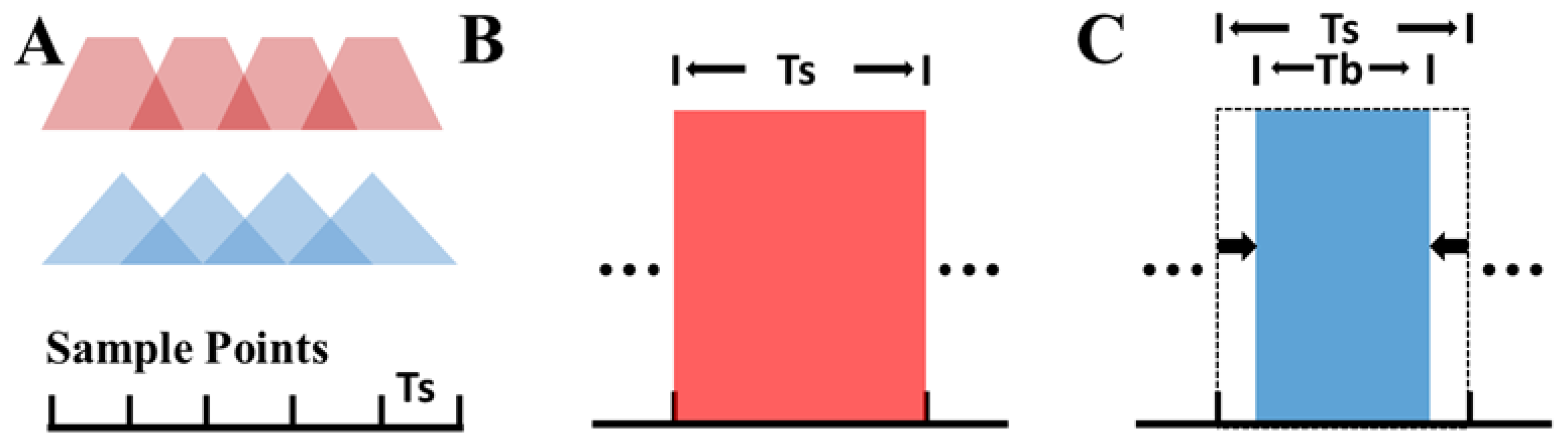
is the corresponding center wavelength without CP being inserted. In the receiver, Sinc-shaped filtering with the same bandwidth as the WSS can be performed on the signal. When the bandwidth
of the Sinc-shaped filter is greater than
, the CP will be inserted into each symbol period, as shown in
Figure 2:
The AO-OFDM signal with CP inserted at the receiving end can be expressed as follows through the corresponding Sinc-shaped filter at the receiving end:
where
represents the frequency domain function of the Sinc-shaped filter bank,
fbm represents the center frequency of the
mth Sinc-shaped filter at the receiving end, and
hm(
t) represents the corresponding time domain function. It is worth noting that the bandwidth of the filter at the receiving end is the same as the symbol rate.
rk(
t) and
smk(
t) are the waveform and pulse-shaping function of the
kth subcarrier. When
m is equal to
k, that is, when the target subcarrier passes through the corresponding Sinc-shaped filter with the same center frequency, the pulse-shaping function is
smk(
t)
(m=k). The adjacent orthogonal sub-carriers will also pass through the filter, and the pulse-shaping function is
smk(
t)
(m≠k) after filtering. Combining Equations (10) and (11), we can clearly see that, when the AO-OFDM system inserts CP, there is a flat range for each symbol period after filtering at the receiving end, and the flat range lasts for
Ts Tb = 1
/fs 1
/fb. This approach will not destroy the orthogonality due to CP insertion and is not affected by other sub-carriers. The larger the filtering bandwidth of the Sinc-shaped filter at the transmitting end, the more CP is inserted. Although the larger the CP, the lower the spectrum utilization rate of the AO-OFDM system and the larger the flat interval in each symbol period, this interval can allow more sampling time errors.
2.2. Analysis of Anti-Dispersion Ability
We propose the use of a Gauss-shaped filter instead of a Sinc-shaped filter at the transmitting end can improve the system’s anti-dispersion capability. As the orthogonal sub-carriers of the WSS—based AO-OFDM system are supercontinuum-filtered by the WSS, the frequency-domain function of the all-optical filter directly controls the frequency-domain waveform of the sub-carrier.
The AO-OFDM signal with CP generated by using a Gauss-shaped filter can be expressed as:
where
u′
k(
t) and
g′
cp(
t) are the waveform and pulse-shaping function of the
kth subcarrier. The frequency domain waveform of the Gauss-shaped filter is:
where
fbk is the center frequency of the Gauss-shaped filter corresponding to the
kth subcarrier with the filter bandwidth of
fs after inserting CP. Different from using a Sinc-shaped filter to insert the CP, the Gauss-shaped filter increased the sub-carrier spacing without increasing the filter bandwidth. As shown in
Figure 3, the Gauss-shaped filter was highly similar to the Sinc-shaped filter with a bandwidth of
fs when the intensity was greater than −6 dB.
The left axis in
Figure 3 shows the amplitude response of the two filters’ waveforms with frequency, and the right axis shows the phase response curve of the two filters with frequency. The blue dotted line represents the Gauss-shaped filter and the red solid line represents the Sinc-shaped filter. We first analyzed the orthogonality of the AO-OFDM system based on a Gauss-shaped filter under ideal conditions without being affected by other noises. Obviously, the carrier generated by the Gauss-shaped filter did not have strict orthogonality. There was crosstalk between carriers and crosstalk between symbols at the receiving end through the Sinc-shaped filter.
The AO-OFDM signal after passing through the Sinc-shaped filter at the receiving end can be expressed as:
The Sinc-shaped filter used at the receiving end of the two AO-OFDM systems is the same. If the same-sized CP is inserted, the filter function in the frequency domain is
Hm(
f), and
r′k(
t) and
s′mk(
t) are the waveform and pulse-shaping function of the
kth subcarrier, respectively. When
m is equal to
k, that is, when the target subcarrier passes through the corresponding Sinc-shaped filter with the same central frequency, the pulse-shaping function is
skk(
t)
(m=k). The other sub-carriers will also pass through the filter, and the pulse-shaping function is
smk(
t)
(m≠k) after filtering.
erf(·) is the error function and
erfi(·) is the imaginary error function. The sub-carriers that are different from the center frequency of the target filter will inevitably cause inter-carrier crosstalk to the target sub-carrier.
Figure 4 shows the pulse-shaping functions
skk(
t)
(m=k),
smk(
t)
(m≠k),
s′
kk(
t)
(m=k), and
s′
mk(
t)
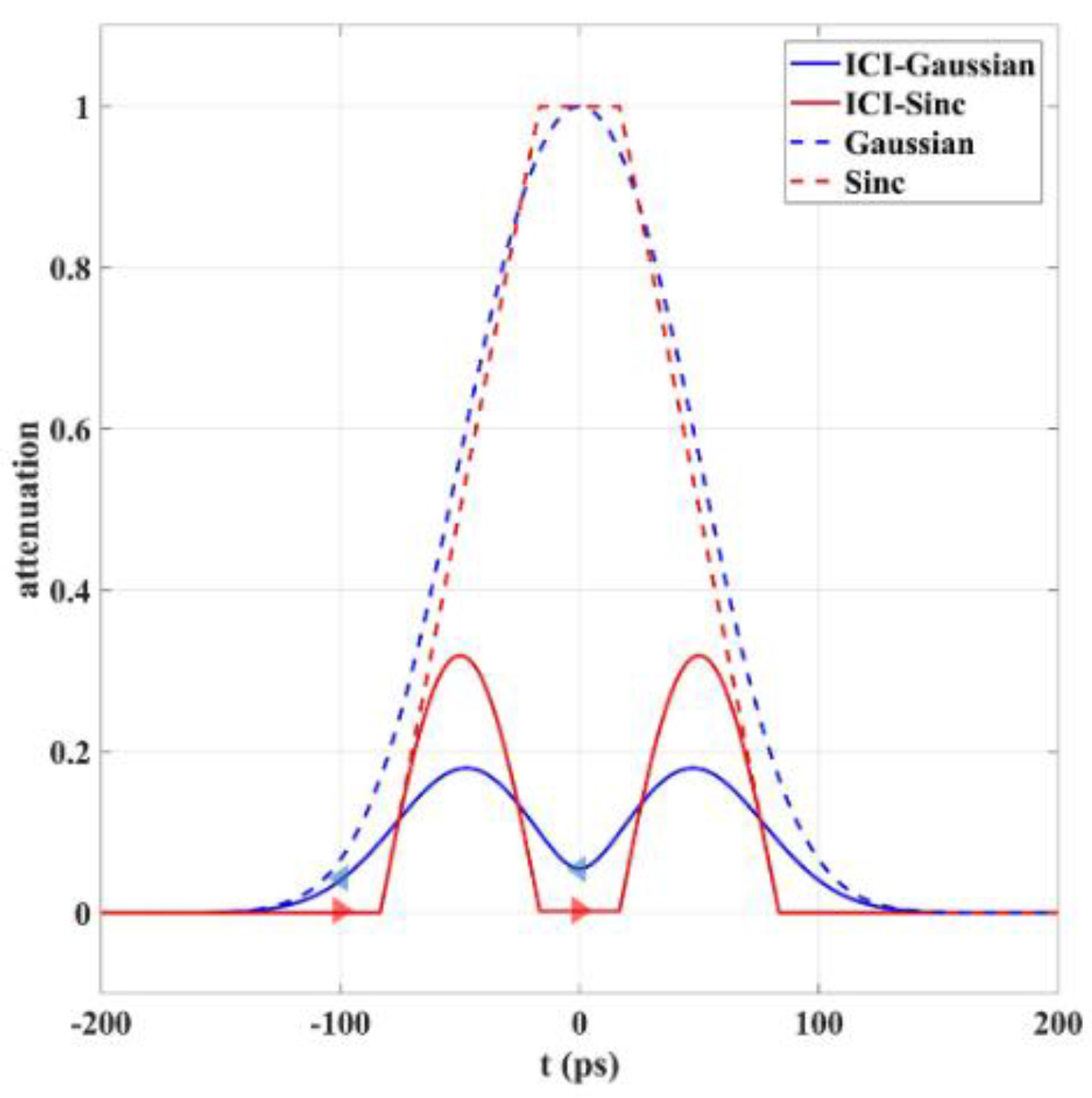
(m≠k) of the two systems with 0 CP inserted and the same subcarrier symbol rate at the receiving end after passing the same Sinc-shaped filter. These four pulse-shaping functions can clearly reflect the crosstalk between carriers after passing the filter. For convenience of comparison, we normalized the four pulse-shaping functions. We discuss the situation of transmitting “1” in an ideal state and receiving “1” after scaling at the receiving end. In the following analysis of the influence of chromatic dispersion on the AO-OFDM system, we also performed the same analysis on these four pulse-shaping functions.
The red and blue dashed lines in
Figure 4 respectively indicate the pulse-shaping function of a certain sub-carrier of the AO-OFDM system using two filters after passing through the corresponding Sinc-shaped filter with the same center sub-carrier. The red and blue dashed lines respectively indicate the crosstalk of adjacent subcarriers suffered by a single period of a certain subcarrier of the AO-OFDM system using two filters. The red lines represent using a Sinc-shaped filter and the blue lines represent the use of a Gauss-shaped filter.
When
t = 0, that is, at the optimal sampling point in each symbol period, the filtered AO-OFDM system was sampled, the symbol
Cki carried by the target subcarrier was obtained, and the crosstalk
e(m−k) from other carriers was also obtained.
The carrier interference (ICI) generated by the
mth sub-carrier passing through the
kth filter, which is the target filter, is shown as the red and blue solid lines. The red and blue triangles in
Figure 4 indicate the ICI of the best sampling point in the current symbol period and the best sampling point in the adjacent symbol period. It can be clearly seen in
Figure 4 that the AO-OFDM system using a Sinc-shaped filter was not subject to crosstalk between adjacent carriers, while the AO-OFDM system using a Gauss-shaped filter was subject to crosstalk between carriers.
Table 1 shows the influence of CP size and ICI on the current symbol period and adjacent symbol period of the AO-OFDM system based on a Gauss-shaped filter.
The CP size in the first row of
Table 1 corresponds to the ratio of the sub-carrier spacing to the symbol rate after the CP is inserted in the second row. The third row in the table indicates the crosstalk of adjacent sub-carriers to the current sub-carrier at the optimal sampling point
t = 0. The fourth row represents the crosstalk of adjacent subcarriers to the current subcarrier for the two adjacent sampling points
t =
±Ts of the optimal sampling point. We can find from
Table 1 that the crosstalk between carriers was the smallest when the inserted CP size was 0.23. The size of ICI was not directly proportional to the size of CP. However, this situation will become complicated under the influence of chromatic dispersion. According to the simulation results, the larger the CP inserted, the better the anti-dispersion ability of the AO-OFDM based on the Gauss-shaped filter and Sinc-shaped filter.
In Ref. [
8], the ICI and Inter-Symbol Interference (ISI) of the AO-OFDM system based on the Gauss-shaped filter were not affected by dispersion, and the frequency domain waveform of the Gauss-shaped filter is discussed in this article. Compared with Ref. [
8], it was closer to a Sinc-shaped filter, and we already made a formula derivation, so we will not discuss the relationship between the ICI, ISI, and CP of the system without dispersion. We will mainly discuss why the AO-OFDM system based on the Gauss-shaped filter was more resistant to dispersion.
The spatio-temporal complex envelope (STCE) of a single symbol period of the kth subcarrier of the AO-OFDM signal along the fiber at position
z and STCE at time
t satisfies NLSE [
18]:
where
α is the loss coefficient,
γ is the nonlinear coefficient, and
is the first derivative of the transmission constant, which reflects that the difference in group velocity between sub-carriers caused the walk-off between carriers. As the sub-carrier spacing in the AO-OFDM system was small and the deviation was not obvious, the envelope was time-shifted with the group velocity during analysis, and only the second derivative of the transmission constant, that is, the influence of the dispersion on the system, was considered.
is the second derivative of the transmission constant, also known as the second-order dispersion effect, which is one of the main causes of signal envelope distortion and is also the main factor affecting the signal transmission quality of the AO-OFDM system mentioned in
Section 1. If only considering the influence of chromatic dispersion on the signal, Equation (22) can be expressed as:
Transforming Equation (23) into the frequency domain can be expressed as:
In Equation (24),
, then the frequency domain waveform of the signal after the transmission distance
z is solved as:
The AO-OFDM system pulse-shaping function
g′
cp(
0,t) based on Gauss-shaped filtering is substituted into Equation (26) to obtain the pulse-shaping function
g′
cp(
z,t) after its pulse-shaping symbol is subjected to dispersion.
After completing Equation (28), the intensity and phase of the pulse-shaping function can be obtained, where
LD is the dispersion length. We found that the pulse-shaping function produced by the Gauss-shaped filter was still a Gaussian function, even after transmission through the optical fiber, with only broadening and phase changes, and the degree of distortion was much smaller than the pulse-shaping function produced by the Sinc-shaped filter. When the transmission distance was much smaller than the dispersion length, there would be no inter-symbol crosstalk due to dispersion. The pulse-shaping function produced by the Sinc-shaped filter was affected by dispersion. The function is difficult to express with mathematical formulas. We will analyze it from
Figure 5 and
Figure 6.
Figure 5 shows the pulse-shaping function
of an AO-OFDM signal based on a Sinc-shaped filter affected by dispersion after being transmitted in optical fibers of different lengths. The symbol period was 100 ps,
. We can see from the change in the pulse-shaping function after being affected by different accumulative dispersions that chromatic dispersion had a great influence on the pulse-shaping function of the symbol, and these distortions were irregular. At
t = 100 ps, the amplitude of the optimal sampling point in the adjacent period changed drastically. Even if the accumulative dispersion was 200 ps/nm, the ISI was already close to 0.1. And the size of ISI did not change regularly with the transmission distance. We can see from
Figure 5 that, as the influence of the dispersion on the system became greater and greater, the energy in each symbol period leaked from the current period to other periods more and more.
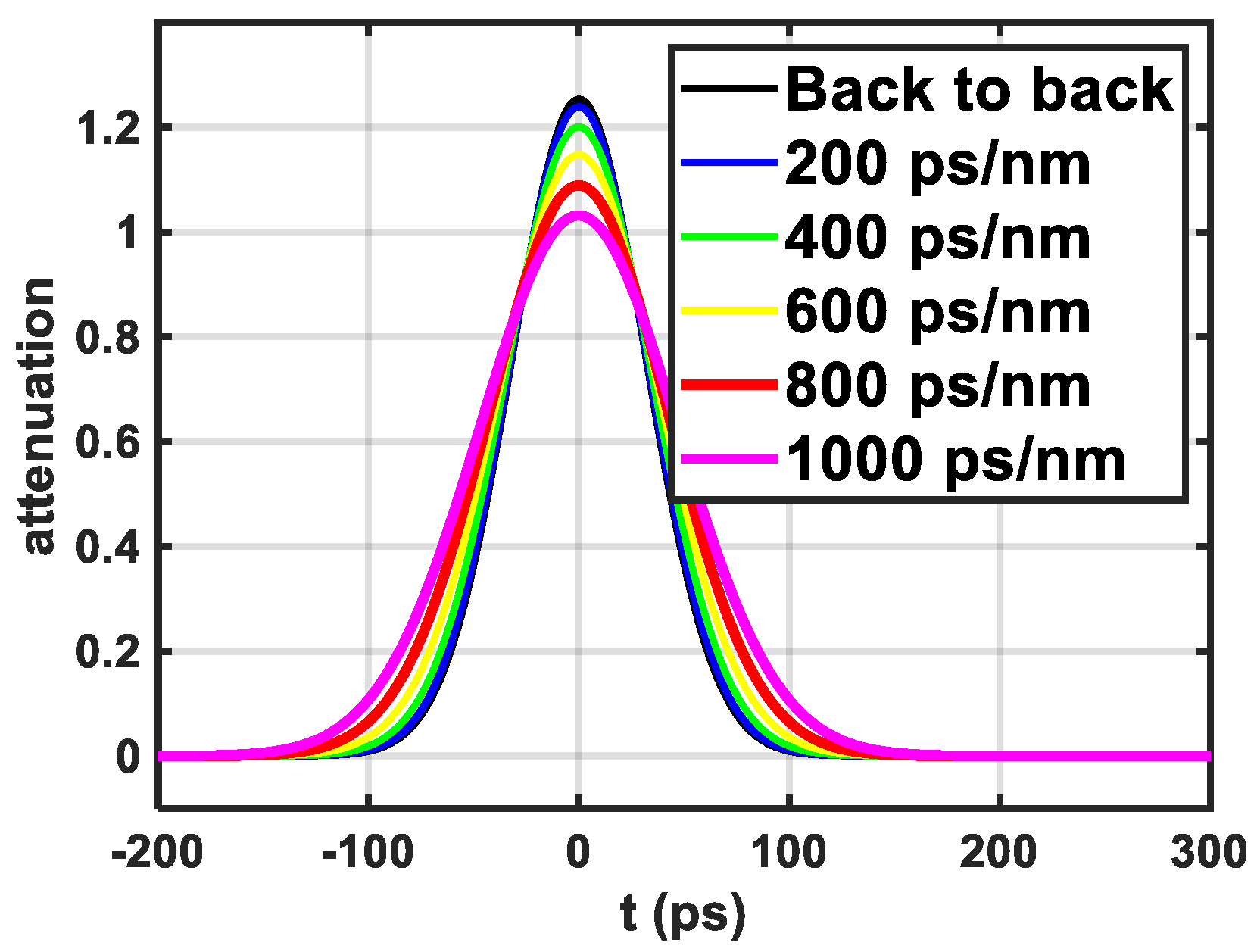
Figure 6 is the pulse-shaping function based on the Gauss-shaped filter as the comparison group of
Figure 5 under the influence of chromatic dispersion, which transmitted different distances in the optical fiber.
From Equation (29) and
Figure 6, we can see that the intensity of the pulse-shaping function generated by the Gauss-shaped filter expanded as the influence of the dispersion increased. Compared with the pulse-shaping function based on the Sinc-shaped filter, the influence of the dispersion at the three sampling points of
t = 0, −
Ts(−100 ps), and
Ts(100 ps)
s was small, and the pulse-shaping function did not have a large distortion.
Figure 7 shows the pulse-shaping function of a certain sub-carrier through the Sinc-shaped filter at the receiving end after being affected by 800 ps/nm accumulative dispersion and the pulse-shaping function of adjacent carrier crosstalk. Similar to
Figure 4, we normalized the received signal. The symbol period was 100 ps, CP = 0.33, and the second-order dispersion coefficient was
. The red triangle to the right and the blue triangle to the left in
Figure 7 represent the ICIs of the best sampling points of the two AO-OFDMs in the current symbol period and adjacent cycles. We can see that the crosstalk between the carriers of the AO-OFDM system based on the Sinc-shaped filter was much greater than the crosstalk between the carriers of the AO-OFDM system based on the Gauss-shaped filter. In order to more intuitively analyze the relationship between the ICI and the transmitter filter, we converted the CP size into the filter bandwidth and center frequency interval. When the CP was 0.17, 0.23, 0.29, and 0.33, it was converted when the symbol rate was 10 Gbaud, and the bandwidth and center frequency spacing of the Sinc-shaped filter were 12 GHz, 13 GHz, 14 GHz, and 15 GHz, respectively. Although the transmission performance of the system could be improved after the CP was inserted, this also reduced the spectrum efficiency, so we will not discuss the case of inserting a larger CP into the AO-OFDM system.
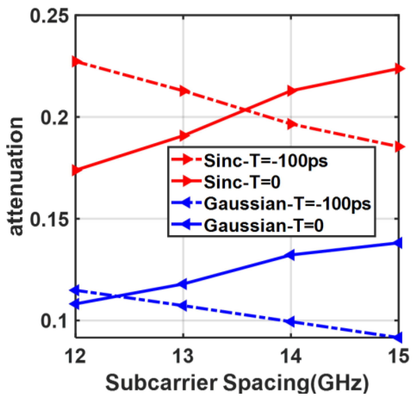
Figure 8 shows the ICI of the adjacent sub-carrier to the target sub-carrier after the target sub-carrier of the AO-OFDM system with a symbol rate of 10 Gbaud was affected by 800 ps/nm accumulative dispersion. The blue line in
Figure 8 represents a system based on a Gauss-shaped filter, and the red line represents a system based on a Sinc-shaped filter. The dotted line represents the influence of ICI on the optimal sampling point of the current symbol period and the solid line represents the influence of ICI on the optimal sampling point in the adjacent symbol period. On the whole, although the AO-OFDM systems based on Sinc-shaped filters were orthogonal to each other during back-to-back transmission without ICI, their ICI exceeded that of systems using Gauss-shaped filters after being affected by dispersion.
Figure 8 shows that, although the size of the inserted CP could affect the ICI of the AO-OFDM system, the ICI of the AO-OFDM system based on the Gauss-shaped filter was always smaller than that of the system based on the Sinc-shaped filter after 40 km of transmission.
In the next part, we will explain the superiority of the Gauss-shaped filter over the Sinc-shaped filter from another aspect.


