1. Introduction
Over 30 years have passed since P. Coullet observed a unique optical phenomenon in a laser cavity and discovered similarities to superfluid vortices [
1]. This phenomenon was later named the optical vortex. Since then, the generation and application of vortex beams have emerged as a research hotspot because vortex beams with orbital angular momentum (OAM) have more freedom in the interaction between light and matter, and are widely used in new system laser radars, laser processing, high-density optical storage, high-resolution imaging, and other fields [
2,
3,
4,
5,
6,
7]. In 1992, Allen firstly discovered that the optical vortex in vortex beams carried orbital angular momentum during the propagation of near-axis beams. Based on this discovery, extensive research has been conducted on vortex beams [
8]. Following this revelation, researchers delved into the manipulation of optical properties and it was in 1993 when M. W. Beijerbergen introduced a phase difference into an incident Hermite–Gaussian beam by using a pair of cylindrical lenses, enabling the preparation of Laguerre–Gaussian modes [
9]. The potential for practical applications came to fruition in 1995, when he successfully harnessed OAM optimized optical tweezers to induce particle rotation [
10]. By 1997, Soskin furtherly explored the complex behavior of vortex beams’ topological charges during propagation, deepening our understanding of their unique characteristics [
11]. Notably, M. Reicherter’s pivotal work in 1999 leveraged liquid crystal displays to generate vortex beams and used them to trap and manipulate polystyrene particles [
12]. In the early 21st century, the implications of vortex beams extended into the realm of quantum phenomena. In 2001, Zeilinger and his team unveiled quantum entanglement within OAM states, paving the way for intriguing prospects in incorporating optical vortices or twisted photons into quantum applications [
13]. In the same year, Paterson et al. achieved controlled rotation of optically trapped microparticles within a spiral interference pattern, offering significant applications in optical and biomedical micromechanics [
6]. By 2008, Barreiro et al. introduced an encoding technique utilizing OAM, conferring significant advantages to vortex beams for their application in the field of optical communication [
14]. By 2011, Capasso and colleagues unveiled a comprehensive framework for reflection and refraction, revolutionizing the generation of optical vortices on nanoscale metasurfaces. Their work greatly improved the design of light beams [
15]. Steering towards 2013, Willner’s team achieved a milestone by demonstrating terabit-scale optical communication through OAM multiplexing in fibers. This breakthrough highlighted OAM’s potential for enhancing data multiplexing in future fiber networks [
16]. Fast-forwarding to 2018, Xie et al. designed a wideband on-chip OAM transmitter, elevating information capacity in optical communication and solidifying its application in the field [
17].
In essence, vortex beams represent a distinct class of beams characterized by their helical wavefronts and non-uniform polarization [
18]. Propagating with spiral phase along their axes, vortex beams feature phase singularities at their centers with zero intensity. Their remarkable property of possessing both angular and rotational momentum confers heightened channel capacity through the OAM generated by the helical phase wavefronts. The phase gradient force further expands their practicality across diverse fields, from high-density optical storage to precision optical manipulation. Precisely owing to these factors, the methodologies for generating vortex beams have ignited profound interest among researchers, giving rise to an extensive array of proposed techniques for vortex beam generation. Notable milestones include M. W. Beijersbergen’s pioneering work in 1994, which demonstrated through experimentation that a spiral phase plate could convert TEM laser beams into spiral wavefront beams with phase singularities along the axis. This innovative work provided a novel approach to generating a vortex phase [
19]. By 2002, Biener et al. proposed a method for creating a spiral phase front using artificial, anisotropic, non-uniform media based on subwavelength gratings [
20]. Fast-forwarding to 2015, L.X. Chen et al. harnessed spatial light modulators to produce multiple superposition states of vortex beams [
21]. In 2017, C. Alpmann et al. achieved a breakthrough in generating intricate Poincaré beams through innovative techniques such as amplitude and phase modulation, coupled with spatial polarization structuring, opening new avenues for quantum communication and optical manipulation [
22]. By 2020, the research group of Y. Ren achieved the preparation of high-order vortex beams by proposing a cross-phase method in which no optical components were involved [
23]. The year 2021 marked a significant leap, with M. Liu et al. demonstrating the feasibility of utilizing all-dielectric metasurfaces to generate generalized perfect Poincaré beams, showcasing potential applications in optical information encryption [
24]. Despite the considerable research efforts dedicated to vortex beam generation, certain limitations such as large mechanical modulation errors and limited bandwidths of meta-structured devices still persist in existing methods [
25,
26,
27,
28,
29,
30,
31].
The utilization of phase, amplitude, and polarization are the most important method to control and manipulate light filed. As an innovative form of phase plate, Pancharatnam–Berry (PB) phase optics exhibits remarkable performance in both phase control and polarization manipulation. They are inherently polarization sensitive, in contrast to dynamic phase devices. At present, an increasing number of PB phase optical components have been developed, including polarization gratings (PGs), q-plates, forked polarization gratings (FPGs), and Airy beam cubic phase plates, among others. In order to generate vortex beams precisely and without narrow bandwidth limitation, we propose a novel broadband vortex beam modulating system based on electrically controlled LC devices that mainly consist of an LC q-plate and an LC broadband PG. Theoretically, the system holds the potential to achieve phase modulation for wide-spectrum vortex beams. Experimental investigation has been conducted on the diffracted optical patterns within the +1st diffraction order’s vortex component, employing lasers with wavelengths of 533 nm and 632.8 nm. The experimental results substantiate the practical viability of the proposed theoretical model. This system enables broadband pure phase control. Furthermore, by incorporating electrically controlled LC devices, independent intensity modulation can be achieved. As a versatile broadband vortex beam generator, this system not only facilitates the generation and modulation of a perfect vortex phase but also allows precise control of the output intensity of the vortex part and Gaussian part by adjusting the voltage applied on the electrically controlled LC q-plate [
32,
33,
34]. Our work provides a fully electrically controlled,, convenient, efficient, low-cost, high-precision, and easily integrative optical system for vortex beam generating and modulating, and is expected to expand the applications of vortex beams in national defense and military fields such as optical communication, laser processing, high-density optical storage, high-resolution imaging, and quantum technology [
35,
36,
37,
38,
39,
40,
41].
2. Theoretic Basis
We use two visible lasers with different wavelengths (
= 632.8 nm and
= 533 nm) as the incident laser source to verify the broadband profile of this vortex beam modulating system. Firstly, the incident beams are converted into left-handed circularly (LHC) polarized beam through a Gran polarizer and a quarter-wave plate (QWP). We can express the incident beams in terms of the Jones vector as follows:
The Jones matrix of q-plate with electrically controlled phase retardation is as follows [
42]:
wherein the orientation of the optical axis
and phase retardation
.
represents the azimuthal angel in Cartesian coordinate system,
q represents the topological charge of the q-plate, and
is the initial angle between the orientation of the optical axis and the
x-axis when
. In this work, we use a q-plate with
.
When two incident beams of different wavelengths enter the q-plate, their retardation can be controlled by voltage, the output beam is as follows:
While
for
and
for
and
is related to the voltage applied on the q-plate. Then, the Jones vector of the output beams can be written as follows:
The Jones matrix of a broadband PG with retardation
The slow axis rotates along
x-axis with an angle
and the
p denotes the period of the grating [
43]:
When two beams (
and
) pass through the broadband PG, the final output beams can be written as follows:
The corresponding wavelengths of the two beams are
= 632.8 nm and = 533 nm. The output beams consist of a Gaussian beam and a vortex beam, whose intensity are controlled by the applied voltage on the q-plate. The phase
in Equations (7) and (8) contributes to the spatial separation of LHC and RHC polarized beams. Owing to the following:
wherein
is the separation angle between the LHC and RHC polarized beams, the angle varies with different wavelengths. Thus, the positions of the vortex part and Gaussian part of the output beams with distinct wavelengths are different.
3. Experiments and Results
To validate the broadband vortex beam modulating system based on electrically controlled LC devices, in this work we fabricated an electrically controlled LC q-plate through LC photo-alignment technology. The photoalignment technique offers a number of significant advantages over the “rubbing” treatment of LC cells as it is a highly accurate and non-contact method that avoids rubbing-induced dust impurities and damage to substrates. This method can effectively control the parameters of LC such as anchoring energy, pretilt angle, and orientation, making it particularly suitable and productive for the fabrication of such an LC q-plate. Firstly, 0.5 wt% azo dye SD1 was dissolved into dimethylformamide (DMF) as an oriented layer and spin-coated on two ITO substrates. After that 4 μm spacers were sprayed on one of the substrates, followed by rapid glue encapsulation as a cell. The assembly was then placed on a digital micromirror device (DMD) platform for photo-alignment, where a pre-designed alignment layer with phase variation was imported into the DMD [
44]. Finally, the E7 (from Jiangsu Hecheng Advanced Materials Co., Ltd., Huaihua, China) was injected into the cell to obtain an electrically controlled LC cell with a specific orientation angle. The structure of electrically controlled LC q-plate is shown in
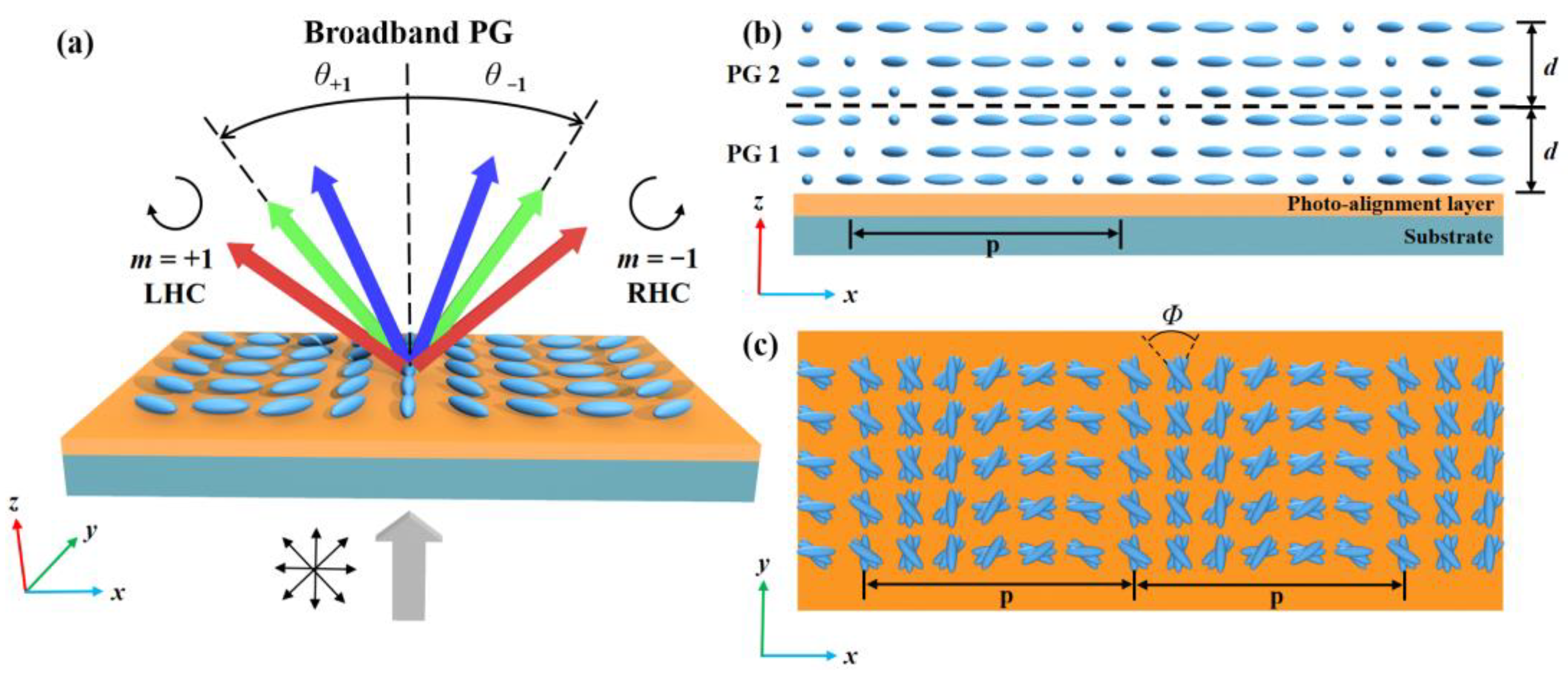
Figure 1a. By changing the applied voltage of the LC cell, rapid control of both the intensity and the transmitted wavelength of the light can be achieved.
We fabricated the broadband PG through the interference exposure method, as illustrated in
Figure 1b. In this process, a 0.5 wt% solution of azo dye SD1 was dissolved in DMF. The solution was then coated onto a glass substrate and spun at 800 rpm for 5 s, followed by spinning at 2000 rpm for 30 s to obtain a uniform film as the alignment layer (Sample). A laser emitting 450 nm linearly polarized light passed through a half-wave plate, adjusting the polarization direction to 45°. The light then underwent spatial filtering using a filtering system comprised of a Gaussian cut-of (GCO) and an adjustable iris (IRIS) to remove higher-order modes and noise, resulting in a clean Gaussian beam. After collimation by a lens, the beam was split into two orthogonal linearly polarized light (transmitted p-light and reflected s-light) by a polarized beam splitter (PBS). The transmitted light was adjusted to overlap with the reflected light using a mirror (MR), and a QWP whose fast-axis orientation is 45° was placed in front of the overlapping region to convert the beams into LHC polarized beam and RHC polarized beams, respectively (with an included angle of 10.36°). The interference patterns were recorded on the alignment layer of the substrate exposed to the beams. Subsequently, a 25% RM-P01 solution (a polymerizable LC material) was mixed with chiral dopants (S811 with left-handed helicity and R811 with right-handed helicity, both at a concentration of 0.784%). We then sequentially spin-coated the LC solution doped with different chiral dopants onto the sample. After exposure to nitrogen environment and curing light (365 nm) for 1 min, a broadband PG with a period of 2.5 μm was successfully fabricated. We apply this polarization interferometry for exposing PG because of the large optical path difference between the two beams. The time coherence of the laser is required, and the optical path difference must be ensured to be less than the laser coherence length
, where
and
respectively represent the laser wavelength and spectral line width.
Unlike the conventional diffraction gratings that periodically operate the amplitude or dynamical phase of light, LC PGs periodically modulate the PB phases of light by spatially changing the anisotropy parameters across the plane of the elements in a periodic way. Broadband PGs has more than four-fold the bandwidth of traditional PGs (and is significantly larger than any other grating). The diffraction angle and operational region (visible, near-infrared, mid-wave infrared, and ultraviolet wavelengths) may be easily obtained during the manufacturing process. We demonstrate a broadband and thin-film polarization grating based on an anisotropic diffraction grating composed of reactive mesogens (polymerizable LCs). The broadband PG used in our experiment is depicted in
Figure 2. This device leverages the achromatic properties of two antisymmetric chiral layers which act as self-compensators eliminating the dispersion in linear and warp-induced circular birefringence. When a linearly polarized light is incident on the broadband PG, the output beam can be decomposed into two circularly polarized beams with opposite handedness: LHC polarized beam with diffraction order
and RHC polarized beam with diffraction order
, as shown in
Figure 1a. The broadband PG consists of two chiral PG layers, as illustrated in
Figure 1b. PG 2 has a slight relative phase shift with respect to the birefringent profile of PG 1. Both layers have the same thickness and opposite twist angle
[
45].
Figure 3a shows the broadband PG observed under the polarization microscope. The period of the measured broadband PG is 2.5 μm;
Figure 3c shows the use of ordinary PG to observe the screw placed in the back. Due to its large zero-order diffraction leakage, the specific shape of the screw can be clearly observed.
Figure 3d is the screw observed at the same distance using broadband PG.
This broadband PG exhibits practically ideal properties, with high 1st-order efficiency, high polarization selectivity, low scattering, and low non-first-order leakage. Therefore, zero-order leakage of broadband PG is significantly reduced by comparison with ordinary LC PG. Spectrometers are used to measure the 1st-order efficiency spectrum of ordinary LC PG and broadband PG. The transmittance of ordinary LC PG is larger only when the half-wave condition is satisfied. For broadband PG, the transmittance is greater than 95% in the band from 450 nm to 800 nm, and the transmittance is measured separately at 533 nm and 632.8 nm, which are 96.74% and 98.62%, respectively. The result is shown in
Figure 3e. We measured the diffraction efficiency of broadband PG with wavelengths of 533 nm and 632.8 nm, and the uniform linear polarized light produced by a monochromatic laser was divided into three beams of ±1 and 0 order through PG; here, the efficiency is calculated as
, where
is the light intensity of the diffraction order measured with optical power and energy meter (Thorlabs, PM100D). The calculated average diffraction efficiency of broadband PG is up to 97.63%.
Figure 3f shows the LC q-plate image under polarization microscope, and there is a changing phase structure on the surface.
Figure 3g is the intensity pattern of vortex beam with topological charge
generated by an LC q-plate.
Experimental setup for the broadband vortex beam modulating system is shown in
Figure 4, two lasers with different wavelengths (
= 632.8 nm and
= 533 nm) are used as the laser sources. Firstly, we used Gran polarizer and QWP to convert the incident beams into LHC polarized beams. Then, the beams were coupled together by a BS. After that, the beam propagated into a series of devices consisting of a q-plate with voltage-controlled phase retardation and a broadband PG, and was finally observed by an observer. We changed the voltage applied on the LC q-plate to adjust the phase retardation of the device, which can modulate the light intensity and the vortex beams of different wavelengths. It should be noted that the incident beams need to coincide exactly when they are incident into a BS. This ensures that the different diffraction angles to different wavelengths generated by broadband PG to be the only reason for the spatially separation of the diffracted light spots. At the same time, the distance from broadband PG to the observer should be kept in the range of 40 cm to 60 cm.
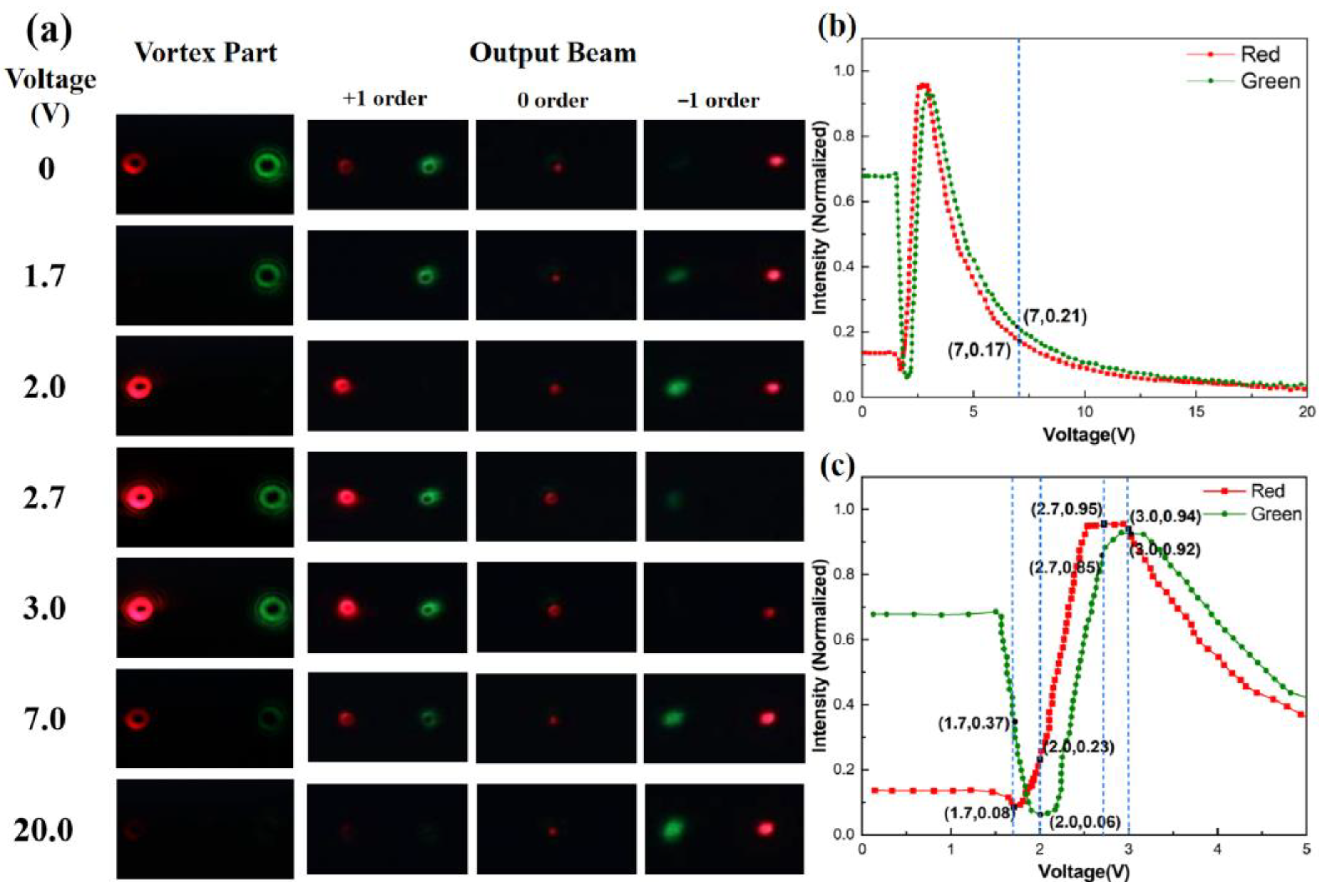
The corresponding diagram of the vortex beams and output beams under different voltages are shown in
Figure 5a. To facilitate the observation of experimentally results, we observed the vortex part by a CCD while the output beam was observed by a camera mounted at a fixed point. Intensity switching of vortex beams with different wavelengths was achieved by manipulating the phase retardation through variations of the voltage applied on the LC q-plate. When different voltages are loaded on the q-plate, the intensities of the Gaussian beam and vortex beam are different. We can see from
Figure 5a that when the applied voltage is 1.7 V,
,
, so the intensity of the vortex part reaches the minimum when the wavelength of the input beam is
. When the applied voltage is 2.0 V,
,
, the intensity of the vortex part reaches the minimum when the wavelength of input beam is
. When the applied voltage is 2.7 V,
,
, the intensity of the vortex part for
reaches the maximum. When the applied voltage is 3.0 V,
,
, the intensity of the vortex part for
reaches the maximum. When the applied voltage is up to 20.0 V,
and
, the intensity of the vortex part for both input beam reaches the minimum.
Hence, we can obtain the intensity modulation of vortex beam and Gaussian beam electrically by altering the phase retardation of the incident beams. Additionally, PGs are optical structures formed by periodic variations in either transmittance or substrate refractive index. When light at wavelengths of 533 nm and 632.8 nm passes through PG, diffraction occurs. In accordance with the wave nature of light, its propagation can be described using wave vectors. The magnitude and direction of the wave vector are dependent on the frequency and propagation direction of the light. Described by the diffraction formula , the spatial separation phenomenon of light of varying wavelengths at ±1 orders on a receiving screen can be elucidated: Here, signifies the diffraction angle, m denotes the diffraction order, and stands for the wavelength of the incident light. The governs the position of diffracted light on the receiving screen. Evident from the formula, the disparate wavelengths of light, due to distinct values of , lead to varying , subsequently yielding differing degrees of spatial separation on the observer’s plane.
The intensity of the vortex parts of the output beams under different voltages are separately measured with optical power and energy meter (Thorlabs, PM100D). In the absence of an electrically controlled q-plate within the optical path, the unaltered optical intensity denoted as
was recorded when laser light (at wavelengths of 533 nm and 632.8 nm) underwent diffraction through broadband PG. Subsequently, following the incorporation of an electrically controlled q-plate into the optical path, a progressive variation of voltage spanning the range from 0 V to 20 V across the terminals of the electrically controlled q-plate was executed, concomitant with the measurement of corresponding optical intensities denoted as
. The normalized optical intensity,
, was determined. Notably, both measurements were conducted at an equidistant distance between the PG and the observer. The results are shown in
Figure 5b,c. We can see from
Figure 5c that as the voltage increases, the light intensity vortex beams with different wavelengths approach maximum and minimum at different voltages. When the voltage is 1.7 V, the vortex part of red light (632.8 nm) reaches minimum; the vortex part of green light (533 nm) reaches minimum when the voltage is 2.0 V. When the voltage is 2.7 V, the vortex part of red light (632.8 nm) reaches maximum; the vortex part of green light (533 nm) reaches maximum when the voltage is 3.0 V.
The transmittance of the broadband polarization grating produced by us is above 95% in the wavelength range from 450 nm to 800 nm. In this paper, the verification results of the vortex beams of 533 and 632.8 nm are satisfactory. The LC q-plate is affected by the external electric field, and the LC molecule will rotate gradually parallel to the direction of the electric field, thus forming an anisotropic LC layer. The LC molecules have a fixed out-of-plane angle (α, also called pretilt angle) and the birefringence of LC molecules is
. When the pretilt angle α gradually increases with the increase in voltage, the
of LC molecule in the
z-axis direction gradually approaches
. The mathematical relationship between α and can be described as follows:
Phase retardation , where is the gap distance of the LC q-plate. The relation between and external voltage can be deduced by elastic continuum theory of LCs; the LC polymer allows high polarization conversion efficient (PCE) and full-range phase modulation for single wavelength light. Therefore, when the voltage is 1.7 V and the red light (632.8 nm) meets the half-wave condition of , the intensity of the +1st diffraction spot received on the observer is approaching 0. Similarly, when the voltage is 2.0 V and the green light (533 nm) meets the half-wave condition of , the intensity of the +1st diffraction spot received on the observer is approaching 0. Thus, we realize the spatial modulation of vortex beams with different wavelengths by controlling voltage.


