Abstract
We propose and experimentally demonstrate a tunable frequency-doubling optoelectronic oscillator (FD-OEO) based on a single-bandpass dispersion-induced microwave photonic filter (MPF) consisting of a Mach–Zehnder modulator (MZM), a linearly chirped fiber Bragg grating and polarization-multiplexed dual-loop. Thanks to the polarization dependence of the MZM, a special double sideband modulation is implemented where the optical carrier (OC) and subcarriers are orthogonally polarized. By simply tuning the PC in the OEO loop, the phase difference between the orthogonal polarization carrier and two sidebands can be controlled, and thus the center frequency of the fundamental OEO can be tuned. Furthermore, a PC and a polarizer are placed outside the OEO to achieve optical carrier suppression (OCS) modulation, which ensures that a frequency-tunable microwave signal at the second-harmonic frequency is generated. In the experiment, a fundamental frequency signal with tunable frequency from 3.6 to 6.85 GHz and FD-OEO with a tunable frequency range from 7.2 to 13.7 GHz are generated.
1. Introduction
Optoelectronic oscillators (OEOs) have aroused significant research interests for their capability in generating high-frequency microwave signals with low phase noise and high spectral purity [1,2]. They are widely applied in the field of optical communications [3], signal processing [4], radio-over-fiber systems [5], sensing system [4] and radar technology [6]. The first OEO [7] was proposed in 1996, which consists of a pump laser and a feedback loop including an electrical filter, an electrical amplifier, etc. Since the phase noise is directly determined by the loop length fluctuation in general, fiber-based OEOs can use long fiber delay lines to obtain a high Q-factor and ultra-low phase noise microwave signals [8,9]. On the other hand, to realize the large-scale deployment of OEOs, integration technology [10,11] using different photonic integration material platforms can be applied. For on-chip OEO methods, a high Q-factor is realized by a long time delay. For example, by using a spiral-shaped optical waveguide as a delay line, the phase noise can be decreased to −92 dBc/Hz@1MHz [11]. In ref. [12], a 40 GHz microwave signal with ultra-low phase noise (100 dBc/Hz@ 10 kHz) was achieved based on a high Q-factor ring resonator using Si3N4 with a 1D superimposed grating.
In the potential application areas of OEOs, the demand for bandwidth is steadily increasing. However, for traditional OEOs, the frequency of the generated microwave signal is relatively low due to the bandwidth limitation of the electrical devices employed in the system. A frequency-doubling OEO (FD-OEO) can generate a microwave signal with a frequency that is two times the bandwidth of the electrical and electro-optical devices in the OEO loop. Therefore, FD-OEOs with a larger bandwidth can extend the operational frequency range, and thus have been researched recently [5]. Apart from the microwave generation, FD-OEOs can also implement advanced optical signal processing such as the optical non-return-to-zero to return-to-zero format conversion [13], photonic frequency down/up-conversion [14,15], serial-to-parallel conversion [3] and clock recovery [16], which cannot be achieved by a traditional OEO. Shin et al. proposed an FD-OEO based on the wavelength dependence of the half-wave voltage of an MZM modulator [17]. In this scheme, two lasers at 1550 nm and 1330 nm were applied for the modulation at quadrature and null-transmission points, which were used to produce the low-frequency fundamental signal and the frequency-doubled signal, respectively. The requirement of two optical sources makes the system complicated and inflexible. In order to simplify the system, different kinds of schemes based on the special modulator have been implemented to generate frequency-doubling microwave signals. In ref. [5], an FD-OEO was obtained based on the distributed intensity conversion effect of a special polarization modulator (PolM) [5]. The joint use of a PolM, two optical polarizers and two polarization controllers (PCs) operated as a two-output intensity modulator, which provided the fundamental frequency in the OEO loop and the frequency-doubled optically modulated microwave signal outside the OEO. In refs. [18,19], using the carrier phase-shifted double sideband (CPS-DSB) modulation of the dual-parallel MZM (DPMZM), a frequency-doubling microwave was generated. In ref. [20], an FD-OEO was proposed based on the polarization property of a LiNbO3 modulator, which makes the system simpler and more cost-effective. However, the FD-OEOs mentioned above are not frequency tunable. Recently, several techniques have been proposed for generating frequency FD-OEOs using wavelength-dependent Brillouin frequency shift [21,22] and narrowband phase-shifted fiber Bragg grating (PS-FBG) [23], where the frequency tunability can be achieved by tuning the wavelength of the TLS. However, the quality of the generated signal in the former systems may be degraded since the SBS effect will introduce additional noise. The latter needs a frequency-fixed optical filter to select the optical carrier and one of the second-order sidebands, which may make the system complex and inflexible. In ref. [24], a frequency-multiplying OEO was demonstrated based on cascaded PolM, PM and a PS-FBG. However, the additional modulator is bound to increase the complexity and cost of the OEO. In addition, the generated frequency of the FD-OEOs mentioned above are related to the wavelength of the TLS, and thus the wavelength drifts of the light source will affect the stability of the system. In order to avoid using the TLS, an FD-OEO is proposed based on a PolM and a tunable optical filter (TOF) [25]. By adjusting the bandwidth of the TOF, an FD-OEO can be obtained. Nevertheless, two lasers are required in this scheme which decreases the system’s simplicity and reliability. Furthermore , the use of an expensive TOF and specially designed modulator (PolM) will limit the FD-OEO from low-cost and large-scale deployment.
In this paper, we propose and demonstrate a frequency-tunable FD-OEO based on a microwave photonic filter (MPF) consisting of an MZM, a linear chirped FBG (LCFBG) and a polarization-multiplexed composite cavity. Thanks to the polarization dependence of the MZM, orthogonally polarized double sideband (PO-DSB) modulation can be implemented where the polarization direction of the optical carrier (OC) is orthogonal with that of the subcarriers. In the proposed scheme, an LCFBG is applied as a dispersive element to form a dispersion-induced MPF. The transmission response of the MPF is a function of the changes of the phase shift which can be adjusted by the PC in the OEO loop. By adjusting the PC in the OEO loop, the phase difference between the OC and the first sideband of the optical signal can be tuned, leading to the center frequency change of the MPF. Therefore, the oscillation frequency of the OEO can be simply tuned by tuning the PC in the loop. Finally, a fundamental frequency oscillation signal with frequency tunability can be achieved by employing a tunable MPF in an OEO loop. Meanwhile, by placing a PC and a polarizer outside the OEO, the optical carrier suppression (OCS) modulation can be achieved. Therefore, a frequency-tunable FD microwave signal can be obtained. Compared with other published research works, our proposed FD-OEO is based on the polarization property of the LiNbO3 modulator, which is a common device in optoelectronic systems. Thus, this makes the system simpler and more cost-effective. The proposed technique is more reliable since the instability of the generated signal induced by wavelength drifts of the TLS can be avoided. In addition, neither the tunable optical filter nor the specially designed modulator are required, and thus the complexity and cost of our proposed tunable FD-OEO is much lower than other schemes.
2. Materials and Methods
The schematic diagram of the proposed optically tunable FD-OEO is shown in Figure 1. A lightwave emitted by a laser diode (LD) is fiber coupled to an MZM via a PC (PC1), whose polarization direction is aligned at an angle α with respect to the principal axis of the LiNbO3 crystal of the MZM (noted as the y-axis in Figure 1b). Thus, the optical field of the light after PC1 can be expressed as
where E0 and ω0 denote the amplitude and angular frequency of the OC, respectively. Thanks to the electro-optical property of the LiNbO3 crystal, the half-wave voltage Vπ in the principal axis (x-direction) is around 3.58 times that in the orthogonal direction; therefore, the injected light in the Y-axis is modulated in the form of optical-carrier-suppression (OCS) by the microwave signal with an angular frequency of ωm. The modulation for the light in the X-axis is insignificant. Considering the small-signal modulation, the optical field at the output of the MZM can be written as [26]
where γ is the polarization-dependent loss coefficient in the X-axis, β is the modulation index and is the first-order Bessel function of the first kind. It can be seen that the PO-DSB signal is generated, and the polarization direction of the OC (λ0) is orthogonal with that of the ±1st-order sidebands (λ+1 and λ−1), as shown in Figure 1(b-2).
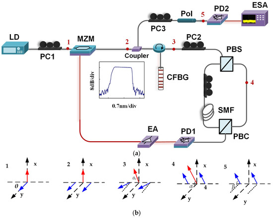
Figure 1.
The schematic diagram of the optically tunable FD-OEO. (a) Schematic diagram of the proposed frequency-tunable OEO. (b) Schematic spectrum evolution at different locations 1–5. LD: laser diode; PC: polarization controller; OC: optical circulator; MZM: Mach–Zehnder modulator; PBS/C: polarization beam splitter/combiner; SMF: single-mode fiber; PD1, PD2: photodetector; EA: electrical amplifier; ESA: electrical spectrum analyzer.
Then, the generated PO-DSB signal is divided into two beams by a 50/50 coupler. One beam is routed to a CFBG via an optical circulator. After the dispersion effect induced by the CFBG, the signal at position 3 in Figure 1a can be written as
where θ0, θ−1, and θ+1 are the dispersion-induced phase shifts of the OC, −1st- and +1st-order sidebands, respectively, as shown in Figure 1(b-3), which can be obtained by
where z is the transmission distance, β(ωc) is the propagation constant at ωc, β’(ωc) is the first-order derivatives of β(ωc), and is the second-order derivatives of β(ωc), where D is the dispersion of the CFBG.
Then, the signal is sent to PBS via PC2. The signal generated after PBS can be written as
where φ0 is the phase difference between the two orthogonal components (Ex and Ey) of the signal at PBS, and α is the angle between the principal axis of the PBS and the principal axis of the MZM. The corresponding schematic optical spectrum is illustrated in Figure 1(b-4). Note that the φ0 and α can be adjusted by tuning PC2.
Then, the generated signal is sent to a photodetector (PD1), and the output photocurrent can be written as
From Equation (6), it can be seen that the generated microwave signal at ωm has a dispersion-induced power fading coefficient given by . Thus, the power of the generated current varies as the square of ωm, and an equivalent microwave bandpass filter is formed, which can be expressed as
In order to possess a maximum transmittance for the signal at ωm, the absolute value of should be set to one, that is
The above condition can be easily satisfied by changing φ0. Since φ0 can be adjusted by tuning PC2, the maximum transmission response can be shifted to any desired frequency. As a result, the frequency-tunable MPF is realized.
To further investigate the relationship between the dispersion of the CFBG and the frequency response of the MPF, we substitute the equation into Equations (7) and (8). The frequency response of the MPF and the condition of the maximum transmission response can be rewritten as
when the dispersion of the CFBG is −1225 ps/nm (D = −1225 ps/nm), the frequency response of the MPF is shown in Figure 2a. Figure 2b presents the frequency response of the MPF at different values of φ0, which can be changed by PC2. It can be seen that by adjusting PC, the peak of the response is tuned from 4.5 to 7 GHz and 10 GHz when φ0 is tuned from 0.2π to 0.5π and π. Finally, the fundamental frequency signal with tunable frequency is generated by tuning PC2, and then it is injected back to the MZM via an EA to form the OEO loop.
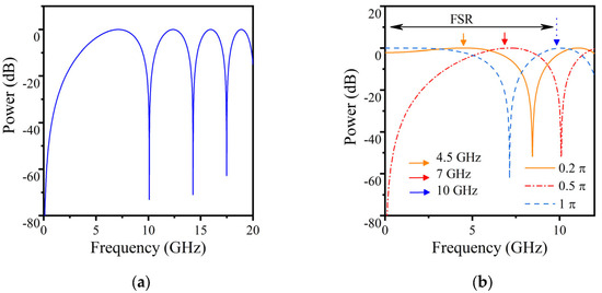
Figure 2.
The frequency response of the MPF at (a) D = −1225 ps/nm and (b) φ0 = 0.4π, 0.5π and 2π.
It is worth noting that a two-tap MPF is formed in the OEO loop by the polarization-multiplexed dual-loops using a PBS and a PBC. The frequency response can be denoted as
where Δτ is the time delay difference induced by the two sections of fiber in the dual-loops, which can finely select the oscillation mode to guarantee a tunable OEO with single-mode oscillation. The frequency-tuning step is determined by the FSR of the comb filter, which is the PMF and equal to 1/∆τ.
Another beam after the optical coupler is injected into a polarizer (Pol) via a PC3. By adjusting PC3, the polarization direction of the OC is oriented 90° with respect to the principal axis of the Pol. In this case, the optical field of the modulated light after the Pol is given by
From Equation (11), an equivalent OCS modulation scheme is achieved since the OC is suppressed after the Pol and the ±1st-order sidebands are reserved. The schematic optical spectrum at position 5 is illustrated in Figure 1b. By beating the two optical wavelengths at PD2, a high-quality FD microwave signal at 2ωm is generated. Since the fundamental signal can be tuned using the PC2 in the OEO loop, the frequency of the generated FD signal can be tuned accordingly by adjusting the PC2.
3. Results and Discussion
An experiment based on the configuration shown in Figure 1a was performed. The parameters of the major devices in the experiment are given as follows: The wavelength of the linearly polarized lightwave from the TLS (Agilent81600B, Santa Clara, CA, USA) was 1550.26 nm. The polarization-dependent MZM had a 3 dB bandwidth of 10 GHz. The optical spectrum was measured by an optical spectrum analyzer with a resolution of 0.01 nm. An electrical spectrum analyzer (ESA, Agilent N9010A, 9 kHz∼26.5 GHz) was employed to monitor the electrical spectrum of the generated fundamental and FD microwave signals. The PD1 and PD2 used in the experiment had a 3 dB bandwidth of 10 GHz and 20 GHz, respectively. The length difference of the polarization-multiplexed dual-loops was 12 m. The LCFBG used in the OEO loop had a 3 dB bandwidth of 0.9 nm and a chromatic dispersion of −1225 ps/nm. The reflection response of the LCFBG is shown as the inset of Figure 1a.
By closing the feedback loop, the OEO begins to self-oscillate at frequencies around the transmission peak of the MPF when the loop gain exceeds the threshold. The polarization-multiplexed dual-loops are performed to complete the fine mode selection of the OEO. Figure 3a shows the optical spectrum of the generated signal after PBS (position 4 in Figure 1) in the OEO loop. The corresponding electrical spectrum and the zoomed-in view of the fundamental oscillating signal at a frequency of 5.27 GHz are shown in Figure 3b,c. The side mode suppression ratio of the generated signal is larger than 50 dB. Furthermore, the free spectral range (FSR) of the OEO was measured to be about 3 MHz, as shown in Figure 4c, which was determined by the length of the SMF in the OEO loop, i.e., about 66 m.
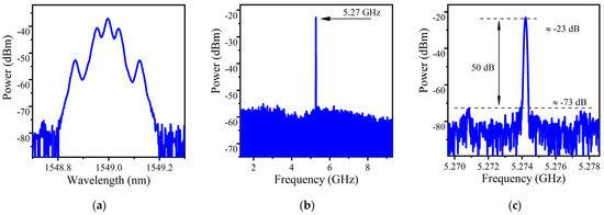
Figure 3.
(a) The RF spectrum, (b) electrical spectrum and (c) zoomed-in view of the electrical spectrum of the signal after PBS (position 4 in Figure 1) in the OEO loop.
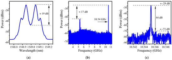
Figure 4.
(a) The RF spectrum, (b) electrical spectrum and (c) zoomed-in view of the electrical spectrum of the FD signal after PBS (position 5 in Figure 1) in the OEO loop.
In order to realize the FD signal, we adjusted the PC3 to set the angle between the OC and the principal axis to 90°. Thus, an equivalent OCS modulation scheme was achieved. The corresponding optical spectrum is shown in Figure 4a. The carrier-suppression ratio of the equivalent OCS optical signal can achieve as high as 19 dB. After PD2, the FD microwave signal at 10 GHz was generated, as shown in Figure 4b. The fundamental OEO signal was strongly suppressed to 17 dB lower than the frequency-doubled signal. The inset in Figure 4c shows the zoomed-in view of the generated FD signal within a frequency span of 8 MHz. The side mode suppression ratio of the FD signal was larger than 44 dB.
By tuning PC2 continuously, the wideband tunable fundamental and FD signal were realized. Figure 5 shows the electrical spectra of the generated fundamental signals over a frequency range from 3.6 to 6.85 GHz. The electrical spectra of the generated FD electrical signals are shown in Figure 5b. It can be seen that an FD signal with a frequency tuning range from 7.2 to 13.7 GHz was achieved. In practice, the imperfections in devices and external environmental factors may affect the range and frequency interval of the generated frequencies. For example, the center frequency of the dispersion-induced MPF was related to the bias voltage of the MZM, and the bias drifts of the MZM will directly affect the oscillation frequency of the OEO. Thus, high-stability voltage regulators can be used to decreased the bias drifts of the MZM. From Figure 5, it can be seen that there were some inconsistencies between the experimental results and theoretical calculations. For example, the experimental frequency range was smaller than the theoretical calculation. Additionally, there were some frequency gaps in the experimental results. The gaps were mainly due to the uneven frequency response of the electrical devices (EA and PD) and the inaccurate adjustment of PC4 in the system. In practical applications, electrical devices with a flat frequency response and a FiberBench polarization controller can be used for more accurate polarization manipulation and finer frequency tunability of the OEO signal. Furthermore, the frequency range was mainly determined by the bandwidth of the electrical and electro-optical devices. Thus, in real applications, a modulator, PD, filter and electrical amplifier with higher bandwidths can be used in order to enlarge the frequency range. It should be noted that the generated FD signal at higher frequency in our results had relatively low amplitudes due to the limitation of the PD’s bandwidth. Furthermore, higher-frequency microwave signals can also be achieved using a CFBG with a lower dispersion coefficient.
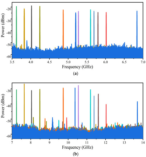
Figure 5.
The electrical spectra for (a) the generated fundamental signals over a frequency range from 3.6 to 6.85 GHz and for (b) the generated FD electrical signals over a frequency range from 7.2 to 13.7 GHz.
4. Conclusions
A tunable FD-OEO using a CFBG based on the orthogonally polarized double sidebands modulation was proposed and experimental demonstrated. Compared with other tunable FD-OEO methods, our proposed scheme is more flexible since the generated signal is independent of the TLS wavelength and the optical filter. Moreover, the proposed method is more attractive and cost-effective since only one commercial MZM is used in the OEO loop, and the specially designed modulator, such as the DPMZM or PolM, is no longer needed. Thus, it can be predicted that the proposed high-quality FD microwave signal generator could be widely applied in various applications, such as radio-over-fiber systems, radars, wireless communications, and electronic systems. For example, for radar systems, taking advantage of the benefits of generating high-quality signals, this kind of OEO can be used to generate multi-frequency signals for multi-band radar [27], the Fourier domain mode-locked signal for chirped radar [28], and the linearly chirped microwave waveform generator for synthetic aperture radar [12]. For radio-over-fiber systems, the OEO can be used to generate the vector signal [29]. For 5G wireless networks, since the OEO has a good phase noise performance at high frequency, the FD-OEO can be applied to generate a high-frequency local oscillator [30], which can meet the requirements of next-generation wireless systems. In real applications, our proposed OEO has the limitations of high power consumption, large size and costly, which need to be addressed. In order to realize the large-scale deployment of the OEO, the photonic-integrated circuit technology of OEOs [31,32] can be applied to make the proposed scheme more compact and cheaper.
Author Contributions
H.W. designed and performed the numerical investigation and analyzed the experimental results. B.W. conceived the idea and conducted the experiments. H.Z., W.W. and G.X. participated in the discussions and contributed to the preliminary experiments. B.W. reviewed the manuscript and supervised the project. All authors have read and agreed to the published version of the manuscript.
Funding
This work was supported by the Beijing Municipal Natural Science Foundation (grant number 4212009), the Youth Innovation Promotion Association CAS (grant number 2023137) and the “Future Star” Talent Fund of the Chinese Academy of Sciences. This work was also performed in the frame of the China Postdoctoral Science Foundation, grant number 314045.
Institutional Review Board Statement
Not applicable.
Informed Consent Statement
Not applicable.
Data Availability Statement
The data that support the findings of this study are available on request from the corresponding author, B.W., upon reasonable request.
Conflicts of Interest
The authors declare no conflict of interest.
References
- Yao, X.S.; Maleki, L. Converting light into spectrally pure microwave oscillation. Opt. Lett. 1996, 21, 483–485. [Google Scholar] [CrossRef] [PubMed]
- Yao, J. Microwave photonics. J. Light. Technol. 2009, 27, 314–335. [Google Scholar] [CrossRef]
- Tsuchida, H. Simultaneous clock recovery and serial-to-parallel conversion of data signals using a polarization modulator-based optoelectronic oscillator. J. Light. Technol. 2009, 27, 3777–3782. [Google Scholar] [CrossRef]
- Yao, J. Optoelectronic oscillators for high speed and high resolution optical sensing. J. Light. Technol. 2017, 35, 3489–3497. [Google Scholar] [CrossRef]
- Pan, S.; Yao, J. A frequency-doubling optoelectronic oscillator using a polarization modulator. IEEE Photonics Technol. Lett. 2009, 21, 929–931. [Google Scholar]
- Xue, Z.; Li, S.; Xue, X.; Zheng, X.; Zhou, B. Photonics-assisted joint radar and communication system based on an optoelectronic oscillator. Opt. Express 2021, 29, 22442–22454. [Google Scholar] [CrossRef]
- Yao, X.S.; Maleki, L. Optoelectronic microwave oscillator. JOSA B 1996, 13, 1725–1735. [Google Scholar] [CrossRef]
- Hao, P.; Niu, J.; Wang, X.; Yao, X.S. Dual-loop diode-tuned Fourier domain harmonically mode-locked opto-electronic oscillator with over 50 dB side-mode spur reduction. Opt. Express 2022, 30, 45569–45582. [Google Scholar] [CrossRef]
- Shifeng, L.; Xiaorui, X.; Fangzheng, Z.; Peng, L.; Xiaochen, K.; Huashan, Y.; Shilong, P. Ultralow phase noise optoelectronic oscillator and its application to a frequency synthesizer. J. Radar. 2019, 8, 243–250. [Google Scholar]
- Hao, T.; Tang, J.; Domenech, D.; Li, W.; Zhu, N.; Capmany, J.; Li, M. Toward monolithic integration of OEOs: From systems to chips. J. Light. Technol. 2018, 36, 4565–4582. [Google Scholar] [CrossRef]
- Tang, J.; Hao, T.; Li, W.; Domenech, D.; Baños, R.; Muñoz, P.; Zhu, N.; Capmany, J.; Li, M. Integrated optoelectronic oscillator. Opt. Express 2018, 26, 12257–12265. [Google Scholar] [CrossRef] [PubMed]
- Brunetti, G.; Armenise, M.N.; Ciminelli, C. Chip-scaled Ka-band photonic linearly chirped microwave waveform generator. Front. Phys. 2022, 10, 158. [Google Scholar] [CrossRef]
- Pan, S.; Yao, J. Optical NRZ to RZ format conversion based on a frequency-doubling optoelectronic oscillator. In Proceedings of the 2009 IEEE LEOS Annual Meeting Conference Proceedings, Antalya, Turkey, 4–8 October 2009. [Google Scholar]
- Lee, J.-Y.; Song, J.-I. Photonic frequency down-converter based on a frequency-doubling OEO using two cascaded EAMs. IEEE Photonics Technol. Lett. 2017, 29, 1529–1532. [Google Scholar] [CrossRef]
- Shin, M.; Kumar, P. Optical microwave frequency up-conversion via a frequency-doubling optoelectronic oscillator. IEEE Photonics Technol. Lett. 2007, 19, 1726–1728. [Google Scholar] [CrossRef]
- Pan, S.; Yao, J. Optical clock recovery using a polarization-modulator-based frequency-doubling optoelectronic oscillator. J. Light. Technol. 2009, 27, 3531–3539. [Google Scholar]
- Shin, M.; Grigoryan, V.; Kumar, P. Frequency-doubling optoelectronic oscillator for generating high-frequency microwave signals with low phase noise. Electron. Lett. 2007, 43, 242–244. [Google Scholar] [CrossRef]
- Liu, X.; Pan, W.; Zou, X.; Zheng, D.; Yan, L.; Luo, B. Frequency-doubling optoelectronic oscillator using DSB-SC modulation and carrier recovery based on stimulated Brillouin scattering. IEEE Photonics J. 2013, 5, 6600606. [Google Scholar]
- Wang, L.; Zhu, N.; Li, W.; Liu, J. A frequency-doubling optoelectronic oscillator based on a dual-parallel Mach–Zehnder modulator and a chirped fiber Bragg grating. IEEE Photonics Technol. Lett. 2011, 23, 1688–1690. [Google Scholar] [CrossRef]
- Zheng, J.; Sun, W.; Wang, W.; Tong, Y.; Wang, W.Y.; Wang, X.; Yuan, H.; Liu, J.; Zhu, N. Frequency-doubling OEO using the polarization property of LiNbO 3 modulator. IEEE Photonics Technol. Lett. 2015, 27, 1864–1867. [Google Scholar] [CrossRef]
- Yang, B.; Jin, X.; Chi, H.; Zhang, X.; Zheng, S.; Zou, S.; Chen, H.; Tangdiongga, E.; Koonen, T. Optically tunable frequency-doubling Brillouin optoelectronic oscillator with carrier phase-shifted double sideband modulation. IEEE Photonics Technol. Lett. 2012, 24, 1051–1053. [Google Scholar] [CrossRef]
- Qiao, Y.; Pan, M.; Zheng, S.; Chi, H.; Jin, X.; Zhang, X. An electrically tunable frequency-doubling optoelectronic oscillator with operation based on stimulated Brillouin scattering. J. Opt. 2013, 15, 035406. [Google Scholar] [CrossRef]
- Li, W.; Yao, J. An optically tunable frequency-doubling optoelectronic oscillator incorporating a phase-shifted-fiber-Bragg-grating-based frequency-tunable photonic microwave filter. In Proceedings of the 2011 International Topical Meeting on Microwave Photonics Jointly held with the 2011 Asia-Pacific Microwave Photonics Conference, Gold Coast, Australia, 18–21 October 2011. [Google Scholar]
- Li, W.; Yao, J. Optically tunable frequency-multiplying optoelectronic oscillator. IEEE Photonics Technol. Lett. 2012, 24, 812–814. [Google Scholar] [CrossRef]
- Li, W.; Liu, J.G.; Zhu, N.H. A widely and continuously tunable frequency doubling optoelectronic oscillator. IEEE Photonics Technol. Lett. 2015, 27, 1461–1464. [Google Scholar] [CrossRef]
- Zheng, J.; Wang, J.; Yu, J.; Zhu, M.; Dong, Z.; Wang, X.; Su, T.; Liu, J.; Zhu, N.; Chang, G.K. Photonic microwave-signal-mixing technique using phase-coherent orthogonal optical carriers for radio-over-fiber application. Opt. Lett. 2014, 39, 5263–5266. [Google Scholar] [CrossRef]
- Zhang, X.; Sun, Q.; Yang, J.; Cao, J.; Li, W. Reconfigurable multi-band microwave photonic radar transmitter with a wide operating frequency range. Opt. Express 2019, 27, 34519–34529. [Google Scholar] [CrossRef]
- Zeng, Z.; Zhang, L.; Zhang, Y.; Zhang, Z.; Zhang, S.; Zhang, Y.; Sun, B.; Liu, Y. Frequency-definable linearly chirped microwave waveform generation by a Fourier domain mode locking optoelectronic oscillator based on stimulated Brillouin scattering. Opt. Express 2020, 28, 13861–13870. [Google Scholar] [CrossRef]
- Zhang, C.; Jin, X.; Jin, X.; Yu, X.; Feng, L.; Yang, H.; Chi, H.; Zhang, X. Photonic vector signal generation based on OEO and optical coherent QPSK modulation. IEEE Photonics Technol. Lett. 2018, 30, 1711–1714. [Google Scholar] [CrossRef]
- Zou, F.; Zou, L.; Yang, B.; Ma, Q.; Zou, X.; Zou, J.; Chen, S.; Milosevic, D.; Cao, Z.; Liu, H. Optoelectronic oscillator for 5G wireless networks and beyond. J. Phys. D Appl. Phys. 2021, 54, 423002. [Google Scholar] [CrossRef]
- Zhang, W.; Yao, J. Silicon Photonic Integrated Optoelectronic Oscillator for Frequency-Tunable Microwave Generation. J. Light. Technol. 2018, 36, 4655–4663. [Google Scholar] [CrossRef]
- Zhang, W.; Yao, J. A silicon photonic integrated frequency-tunable optoelectronic oscillator. In Proceedings of the Microwave Photonics (MWP), 2017 International Topical Meeting, Beijing, China, 23–26 October 2017. [Google Scholar]
Disclaimer/Publisher’s Note: The statements, opinions and data contained in all publications are solely those of the individual author(s) and contributor(s) and not of MDPI and/or the editor(s). MDPI and/or the editor(s) disclaim responsibility for any injury to people or property resulting from any ideas, methods, instructions or products referred to in the content. |
© 2023 by the authors. Licensee MDPI, Basel, Switzerland. This article is an open access article distributed under the terms and conditions of the Creative Commons Attribution (CC BY) license (https://creativecommons.org/licenses/by/4.0/).