Article

Single-Frequency Continuous-Wave Self-Sweeping Fiber Laser Based on Separated Gain and Absorption Dynamics Gratings

by
Ekaterina K. Kashirina
*,
Ivan A. Lobach
and
Sergey I. Kablukov
Institute of Automation and Electrometry, Siberian Branch of the Russian Academy of Sciences, 1 Ac. Koptyug Ave., Novosibirsk 630090, Russia
*
Author to whom correspondence should be addressed.
Photonics 2023, 10(7), 843; https://doi.org/10.3390/photonics10070843
Submission received: 9 June 2023 / Revised: 12 July 2023 / Accepted: 19 July 2023 / Published: 21 July 2023

Abstract

:
A new cavity scheme for a self-sweeping fiber laser with separated gain and absorption dynamics gratings is presented. The scheme is experimentally realized in an Er-doped ring fiber laser generating in the continuous-wave (CW) regime near the wavelength of 1604 nm. Switching between single longitudinal mode stabilization and wavelength self-sweeping regimes is demonstrated by controlling the intracavity losses in the laser. The pump power and optimization of the intracavity losses made it possible to demonstrate record sweeping range of 2.6 nm in a single-frequency self-sweeping regime in the telecommunication L-band.

1. Introduction

Fiber lasers, due to their compactness, high power, high quality of output radiation and a variety of generation regimes, compete with other types of lasers and have a high practical potential for application in various areas of human life. For example, fiber lasers are used in telecommunication [1], material processing [2] and sensing [3,4,5]. A special place among fiber lasers belongs to lasers with tunable wavelength generation (the so-called tunable lasers). As a rule, various controllable spectral selectors, such as fiber Bragg gratings [6], diffraction gratings [7] or interference filters [8], are used to achieve this option. Recently, however, interest has arisen in lasers with passive tuning (which will be referred to henceforth as self-sweeping) of the optical frequency/wavelength, which results from the influence of dynamic population gratings created directly in the laser active medium [9]. Over the past 12 years, the effect of wavelength self-sweeping has been demonstrated in lasers based on most of the known active fiber dopants: ytterbium, thulium, neodymium, bismuth, holmium, and erbium (see review [9] and references therein). Wavelength tuning in the self-sweeping lasers occurs without any external control and results from internal processes of longitudinal modes competition assisted by periodic inhomogeneity of the gain. This periodic inhomogeneity results from periodic saturation of the gain medium originating from intensity pattern in standing wave cavities and is known as spatial hole burning [10] or dynamic gain grating (DGG) [9] in the laser active medium. The wavelength self-sweeping process can be described as follows. The lasing longitudinal mode forms a DGG in the active medium of a self-sweeping laser. The DGG itself, in turn, changes the competition conditions and leads to the generation of another longitudinal mode. Then, the new mode forms another DGG, and the process of the generated mode changing repeats again and again. Such a periodic change in modes/generation wavelengths/optical frequencies repeated multiple times in the same frequency direction is known as the wavelength self-sweeping effect (WSSE).
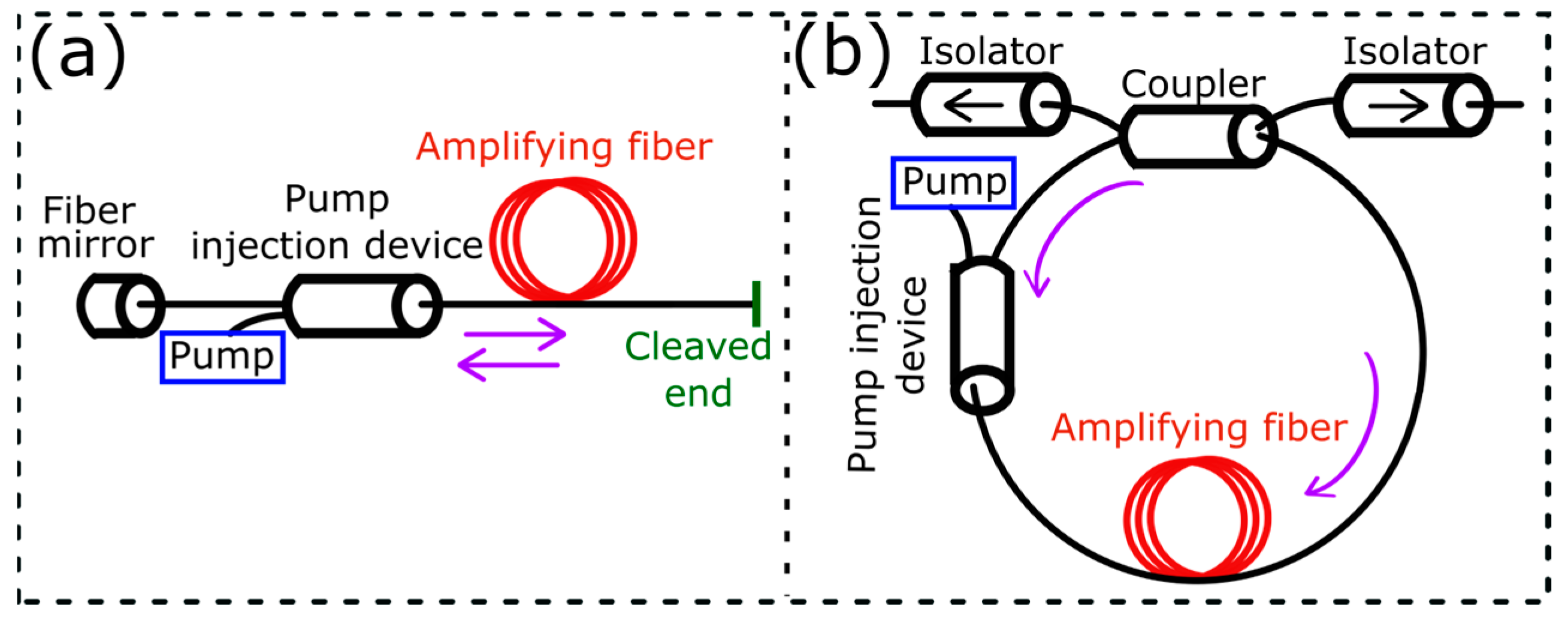
The formation of standing waves is possible in lasers with either linear Fabry–Perot or bidirectional ring cavities (see Figure 1a,b, respectively). It can be expected that the insertion of an additional optical isolator into the ring scheme will have a negative effect on the formation of the DGG and, as a result, will lead to the disappearance of the WSSE. However, it has been found in [11] that if there are no output optical isolators (shown at the output of the ring laser in Figure 1b), then the presence of even a weak Fresnel reflection from the output fiber connector located at the output of a unidirectional ring fiber laser can result in the WSSE. An intracavity optical isolator does not result in wavelength stabilization if the reflected radiation interacts with the laser active medium before it is blocked by the optical isolator. Suppression of the Fresnel reflection (with either an optical isolator or an angled fiber connector) stops the WSSE.
The WSSE in the schemes presented in Figure 1 is accompanied, as a rule, by the generation of microsecond pulses, with the optical frequency changing sequentially from pulse to pulse by multiples of the laser cavity’s free spectral range (FSR). It should be noted that self-sweeping lasers generating single longitudinal mode radiation at each of the microsecond pulses are more attractive for practical applications. The lengths and the relative arrangement of passive and active fibers in the laser cavity should be selected properly to obtain single-frequency self-sweeping operation [12]. Such lasers generate long sequences of pulses (up to ~1 million). Each of the pulses are equidistant in the optical frequency domain, and the sequential generation leads to the laser frequency tuning in a large range of up to 6.5 THz (which corresponds to a ~25 nm wavelength tuning in a self-sweeping ytterbium-doped fiber laser generating at a ~1070 nm wavelength) [9].
It was established in the first works that the WSSE is usually accompanied by the intensity relaxation oscillations [9]. Relatively recently, it was shown in [13] that the generation time of a single longitudinal mode can considerably exceed the relaxation oscillation period in a self-sweeping laser based on usual Fabry–Perot cavity scheme (Figure 1a). The intensity dynamics become closer to continuous ones in such a self-sweeping Er-doped fiber laser. The continuous wave (CW) generation time for each individual mode becomes longer than the repetition period of the generation of new modes, and the time gap between the generation of individual modes disappears. This is the key difference between self-sweeping lasers with CW intensity dynamics and the pulsed ones investigated earlier. The authors of [13] connected the appearance of the CW generation regime to the fact that very long Er-doped active fibers are used and the pump radiation was fully depleted in a shorter segment of the fiber. In this case, a dynamic absorption grating (DAG) is formed in the active fiber in addition to the DGG. Unpumped active fibers act as an absorber for the generated laser radiation. It is known (see, for example, [9] and references therein) that the DAGs contribute to the stabilization of the laser frequency (as opposite to the DGGs). Thus, competition between the opposite effects (self-sweeping and stabilization) leads to pulse lengthening from microseconds to several milliseconds and to an overlapping of the generated pulses in time, which is observed in self-sweeping Er-doped fiber lasers [13] as CW intensity dynamics.
A little later [14], the WSSE with CW intensity dynamics was also demonstrated in laser cavity schemes with fiber-saturable absorbers (Figure 2) traditionally used to stabilize single-frequency radiation [9]. In these schemes, the DAG formed by a standing wave in the absorbing fiber placed in the linear part of the cavity plays a key role. The standing wave selectively saturates the absorption in its anti-nodes for the generated longitudinal mode by recording a DAG. The DAG prevents a change in the generated mode due to an increase in losses for modes having different positions of anti-nodes. Moreover, a circulator (Figure 2a) or an optical isolator (Figure 2b) is usually used to arrange unidirectional wave propagation in the amplifying part of the laser in order to avoid a DGG formation. The possibility of stabilizing the single-frequency generation in such schemes was shown relatively long ago [15], but only recently was the WSSE also demonstrated in them (see [14,16] concerning Yb- and Er-doped lasers, respectively). The transition from single-longitudinal mode stabilization to wavelength self-sweeping with an increase in the pump power at relatively large absorbing fiber lengths was experimentally demonstrated in an Er-doped fiber laser [16] operating in the ring cavity configuration (Figure 2a). The self-sweeping lasers with cavity schemes shown in Figure 2 have CW intensity dynamics with long (up to several milliseconds) overlapping single-frequency pulses. Note that in a single-frequency CW self-sweeping Er-doped fiber laser [16], the spectral tuning range was limited to only a few tens of picometers.
The fact that under certain conditions, the DAG can lead to wavelength self-sweeping instead of optical frequency stabilization, thereby replacing the DGG function of mode competition, has already been discussed in [9]. However, it was noted in [16] that a weak DGG could also be formed in the laser cavity (Figure 2a) due to the limited isolation level of the used circulator because the laser switched to the stabilization mode when an additional isolator was inserted into the ring part of the cavity. So, weak DGGs can be formed even in the cavity schemes presented in Figure 2 and cause a WSSE.
Thus, the analysis of the publications shows that the results on the WSSE in most cases are based on formation of either the DAG or DGG in active fibers. So, in the self-sweeping lasers presented up to now, the WSSE occurs predominantly because of either DAG or DGG. This, in turn, directly affects the intensity dynamics in such lasers (pulsed or continuous wave, respectively).
Here, we present an alternative scheme of a self-sweeping laser, in which both DGG and DAG can be formed explicitly (i.e., not due to parasitic reflection) in different parts of the cavity. In this case, it becomes possible to control the laser generation regime independently influencing the DGG and DAG. As an example, we demonstrate here the possibility of changing the generation regimes between single-frequency stabilization (predominant influence of the DAG) and single-frequency self-sweeping with CW intensity dynamics (simultaneous operation of the DGG and DAG) by introducing controlled losses in the ring part of the laser cavity. Using this approach, we demonstrate here an Er-doped fiber laser operating in single-frequency generation regime in a wide self-sweeping range of 2.6 nm near the wavelength of 1.6 μm, which is important for practical applications.

2. Experimental Setup

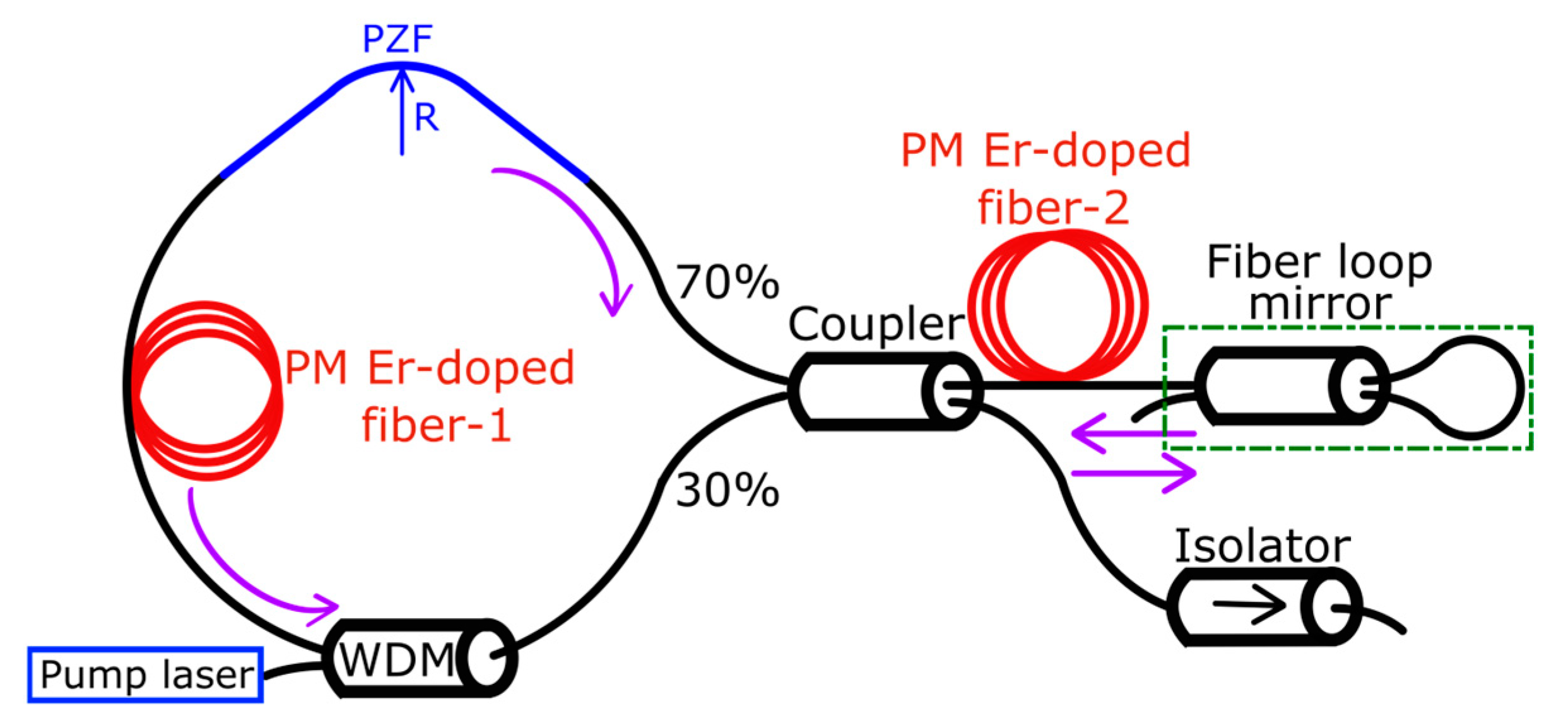
The scheme of a ring Er-doped fiber self-sweeping laser based on polarization-maintaining (PM) components is shown in Figure 3. The laser consists of a ring and linear parts. A 9.6 m long Er-doped fiber, EDF#1 (IXF-EDF-HD-PM, iXblue Photonics), with an absorption ≈ 83 dB/m at 1530 nm is used as an amplifying medium. To obtain generation in the L-band, a relatively large length of a highly Er-doped active fiber is required. The EDF#1 is pumped with a laser diode at wavelength of 1548 nm. The pump power can be increased up to 1 W in an additional Er-doped fiber amplifier. The pump radiation enters the fiber EDF#1 through a reflective port of a wavelength-division multiplexor (WDM) 1540/1610. A 0.8 m long polarizing fiber, PZF, (HB1550Z, Fibercore) is inserted into the ring part of the laser cavity to select the generating polarization state and improve the contrast of DGG and DAG. The radiation transmitted through the PZF enters a 30/70 fiber coupler located in the central part of the cavity. The coupler will be henceforth referred to as the central coupler. A total of 30% of the radiation transmitted through the coupler radiation is out-coupled from the laser cavity, and the remaining 70% of the radiation is directed into the linear part. The linear part of the cavity consists of another 1.8 m long Er-doped active fiber, EDF#2, (Coractive ER35-7-PM), with an absorption ≈ 24 dB/m at a 1530 nm wavelength and a fiber loop mirror (FLM) with a reflectance of ~80%. An optical isolator is installed at the laser output to eliminate the influence of unwanted reflections from measuring instruments on the laser generation dynamics. One standing wave is formed in the linear part of the cavity due to reflection from the FLM and records DAG in the absorbing fiber EDF#2. Another standing wave is formed in the ring part of the cavity because the radiation coming from the linear part is divided by the central coupler into two counter propagating waves. The ratio of the waves’ powers can be controlled by changing the coupling ratio of the central fiber coupler, as well as by introducing additional optical losses in the ring part of the laser scheme. Thus, standing waves in this laser are formed not only in the absorbing fiber but also in the amplifying fiber (EDF#2 and EDF#1, respectively).
Controlling the above-mentioned additional losses, we can change the relative influence of the DGG and DAG on the laser operation. The losses were changed by bending a relatively short (~8 cm long only) section of PZF. It should be noted here that manufacturers of such fibers (for example, Fibercore and IXblue) indicate the presence of sharp transmission spectral dependence. These dependencies have the same spectral shape for both orthogonal polarization states, but they are shifted from each other by ~100 nm. This sharp spectral shape and large spectral shift are used for polarization selection. More details on the operation principles of such optical fibers can be found in chapter 8 of the Optical Fibers Handbook [17]. Spectral position of the sharp growth of the transmission losses depends on bending diameter. The manufacturers recommend winding a 5 m long PZF on a spool with a 90 mm diameter to obtain >30 dB discrimination between two polarizations and have relatively low transmission losses <3 dB for the selected polarization. For example, the HB1550Z (11/125) (Fibercore) PZF can be used in telecom wavelengths ranging from 1500 to 1600 nm [18]. Decreasing the winding diameter shifts the PZF operating range to the shorter wavelengths and makes it narrower. We use a much shorter PZF length (0.8 m) because we do not need to obtain high polarization discrimination to generate a single polarization state in our laser. We experimentally verified that the short PZF does not introduce significant losses for the generated polarization at large bending diameters >130 mm. However, reduction in the bending diameter down to 40 or 60 mm, even if applied to a relatively short (~8 cm) segment of the PZF, allowed us to noticeably increase bending losses and influence the laser power and even the laser generation regime.
Short- and long-term spectral dynamics were analyzed using a wavelength meter (WS6-200, Angstrom/HighFinesse), allowing us to make about 1000 measurements per second. The intensity dynamics of generated radiation were analyzed using a fast photodetector and a digital oscilloscope (Rigol, DS6104) with 1 GHz bandwidth. During the experiments, we investigated the influence of the pump power and additional bending losses on the laser generation. Particular attention was focused on achieving a single-frequency self-sweeping operation with the generation of long pulses, described in [16].

3. Results

3.1. Laser Operation without Additional Losses

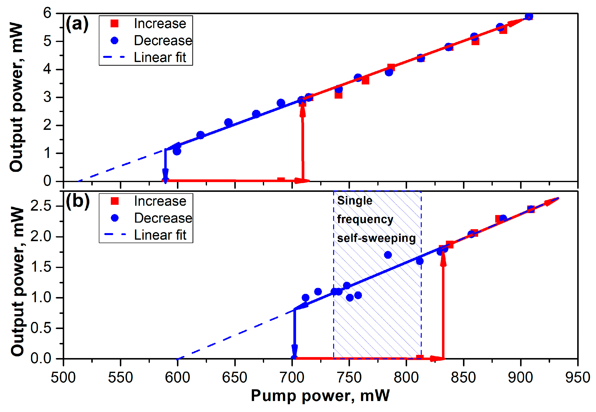
Let us first consider the laser generation regime without introducing additional bending losses (at large bending diameters of the PZF). The dependence of the output power on the pump power is shown in Figure 4a. The hysteresis is present near the generation threshold. One should note that the presence of hysteresis in another self-sweeping Er-doped fiber ring laser was also reported in [16]. As the pump power increases (red points), laser generation starts at an upper pump power threshold of ~710 mW (switch-on threshold). Here, the output power increases in a stepwise manner up to 2.8 mW. As the pump power increases further up to 910 mW, the output power increases linearly up to ∼5.9 mW. The output power decreases also linearly down to ~1 mW as the pump power decreases (blue points). The switch-off (or lower) threshold is ~600 mW. The output power slope efficiency is about ~1.5%. Near the lower threshold, generation becomes unstable and may stop suddenly.
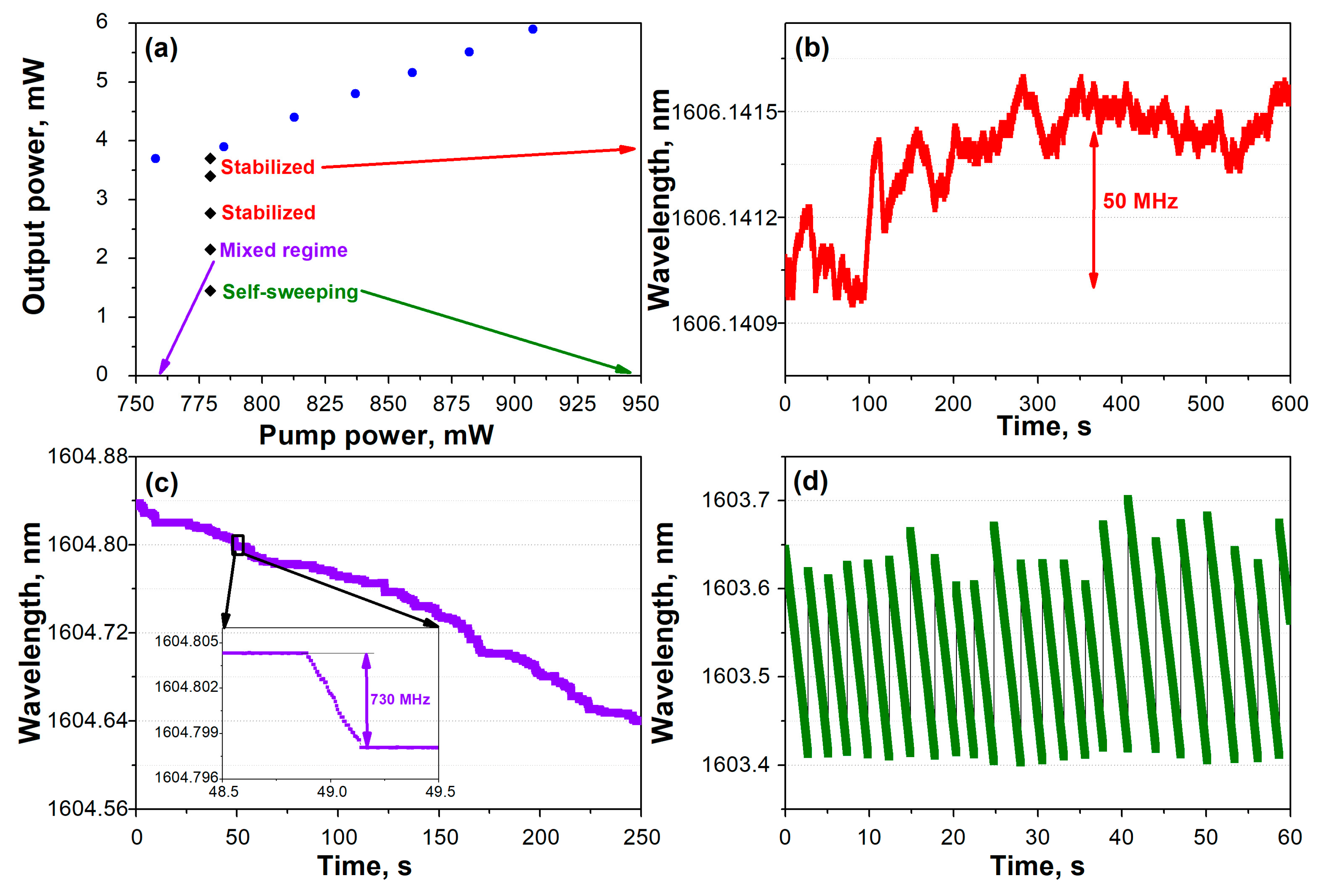
The laser generates near the wavelength of 1604 nm in the telecom L-band, which is typical for Er-doped lasers with long active fibers. The laser generation regime changes with pump power. The laser operates in a single longitudinal mode stabilization regime at low pump powers (from 600 to 780 mW). The characteristic result of long-term (over a 10- min interval) wavelength stability measurements at a pump power of 780 mW is presented in Figure 5b. Figure 5b demonstrates that the wavelength fluctuations lie within a ~0.6 pm (or ~70 MHz in the frequency domain) interval. The generation regime becomes less stable with further power increases. The durations of single longitudinal mode generation periods become shorter, and short intervals with wavelength self-sweeping begin to appear. The repetition rate of the self-sweeping intervals increases with power. One should note that similar wavelength temporal dependencies have also been reported in [16]. Further pump power increases do not result in the stabilization of the self-sweeping operation. The self-sweeping intervals become less regular and accompanied by the simultaneous generation of several longitudinal cavity modes. Thus, we failed to obtain the single-frequency self-sweeping regime without time intervals of frequency stabilization in the laser configuration without introducing additional bending losses. Further research was aimed at optimizing the bending losses and the pump power to obtain a stable single-frequency self-sweeping generation regime.

3.2. Laser Operation with Additional Losses

It was found during further experiments that the introduction of additional bending losses into the ring part of the laser cavity leads not only to a decrease in the output power, but also to a change in the laser generation regime. The influence of the bending losses on temporal wavelength dynamics is demonstrated in Figure 5. The pump power was fixed at a level of 780 mW, and the bending radius of the polarizing fiber was smoothly changed from 6.5 to ~2 cm, leading to a corresponding output power reduction from 3.7 to 1.4 mW. The power reduction is shown with black rhombuses in Figure 5a, where generation regimes are marked with “Stabilized”, “Mixed regime”, and “Self-sweeping” labels. Temporal wavelength dependencies corresponding to these labels are shown in Figure 5b–d, respectively. Let us describe this dependence in more detail. First, the regime of single longitudinal mode stabilization is preserved at large bending radii (the three upper rhombuses in Figure 5a). Then, in addition to the stabilization regime shown in Figure 5b, short intervals of self-sweeping begin to appear. An example of the temporal wavelength dependence in the so-called transient “mixed regime” is shown in Figure 5c. The inset to Figure 5c plotted for a shorter time interval demonstrates that the stabilization can, at some point in time, switch to self-sweeping and back. The self-sweeping intervals are rather short. For example, the inset shows that the wavelength begins to decrease continuously by ~6.3 pm (~730 MHz) over a 0.2 s interval. The stabilization periods and the laser output power decrease with the further reduction in the PZF bending radius. The stabilization periods disappear completely, when the output power decreases down to 1.4 mW (see Figure 5d). The laser operates in the self-sweeping regime with the decrease in wavelength. One should note that the self-sweeping wavelength range is relatively narrow (less than 0.3 nm) in this case. The optical spectrum measured with the Optical Spectrum Analyzer (Yokogawa AQ6370) demonstrates that the OSNR is over 40 dB for all lasing regimes.
Furthermore, the bending losses were fixed at a level corresponding to self-sweeping operation (Figure 5d) and the dependence of the output lasing power on the pump was measured again. The measured dependence (shown in Figure 4b) still exhibits hysteresis with increased values of the both threshold powers. As the pump power increases (red squares), laser generation begins at the turn-on threshold of 830 mW, where the output power increases abruptly up to 1.8 mW. Furthermore, the output power increases linearly with the pump at a slope efficiency of ~0.8% and reaches ~2.5 mW at a pump power of 910 mW. It should be noted that the slope efficiency is reduced by a factor of two compared to the case when we do not apply additional bending losses using PZF. As the pump power decreases down to 710 mW (blue circles), the output lasing power also decreases down to 1 mW. Furthermore, the generation becomes unstable, and the lasing power abruptly drops to zero.
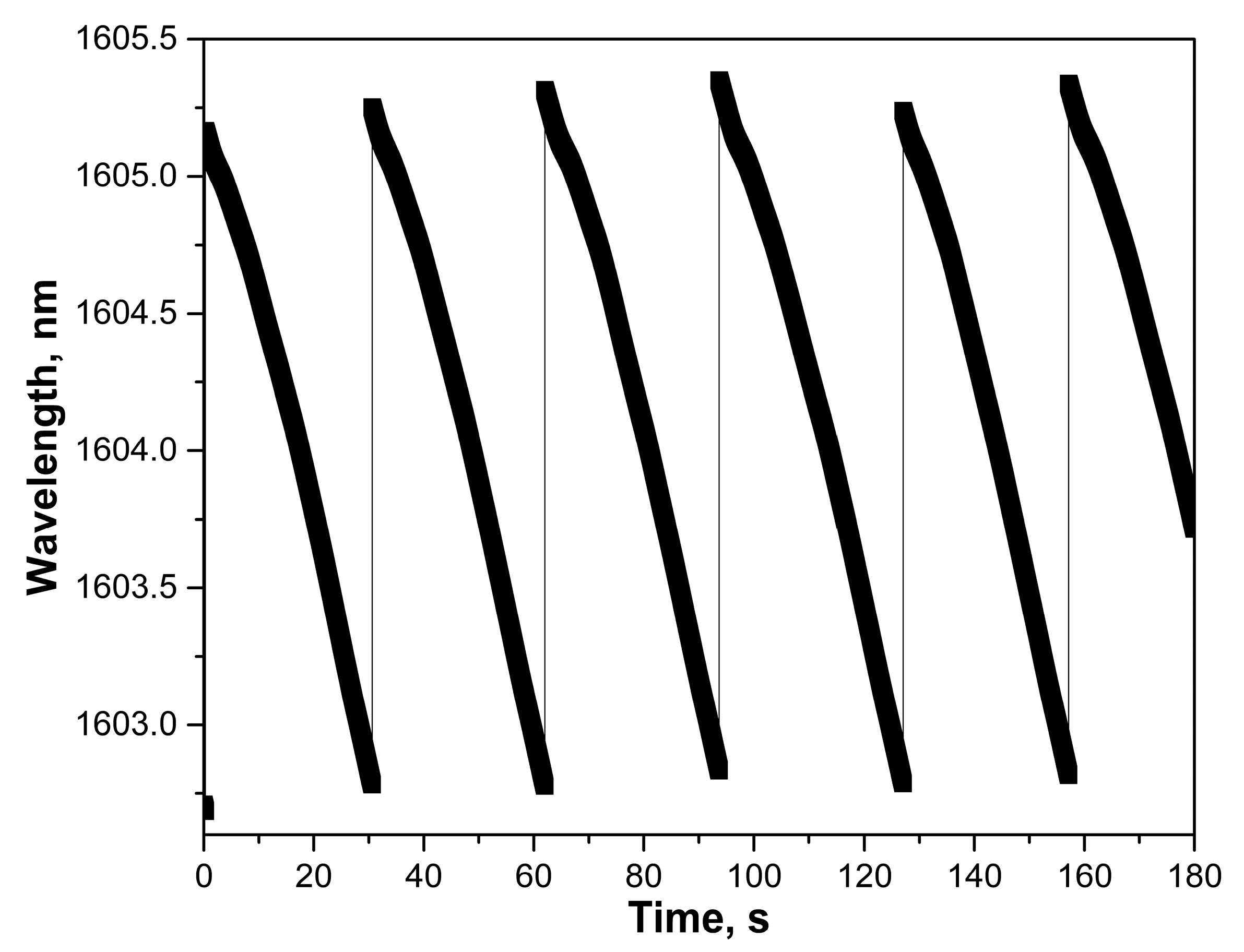
Let us turn to the description of the generation regime near the lower generation threshold. A single longitudinal mode stabilization with rare mode hops is observed at low pump powers (~710 mW). At pump powers ranging from 710 to 730 mW, the laser generates in the mixed regime described above (Figure 5c). The single longitudinal mode stabilization intervals become shorter with the increase in pump power and completely disappear at the pump power of 730 mW. A similar transition from single longitudinal mode stabilization to self-sweeping with the increase in pump power was also reported in [16]. The self-sweeping regime is observed at the pump powers ranging from 730 to 810 mW. The sweeping range does not remain constant. As the power increases from 730 to 810 mW, the sweeping range decreases from 2.6 to 0.2 nm, respectively. In addition, positions of the self-sweeping borders become less stable at higher powers. An example of the generation wavelength’s temporal dependence at a pump power of 740 mW is shown in Figure 6, where the maximum sweeping range is about 2.6 nm. It should be noted that the generation power changes considerably during the wavelength self-sweeping. The output power has a minimum value of 0.67 mW at a starting wavelength of 1605.25 nm and increases up to 1.3 mW at the end of the sweeping (wavelength of 1602.75 nm). The self-sweeping range as well as the output power fluctuations decrease when the pump power increases. Furthermore, we present the laser intensity dynamics measured at maximum sweeping range only.
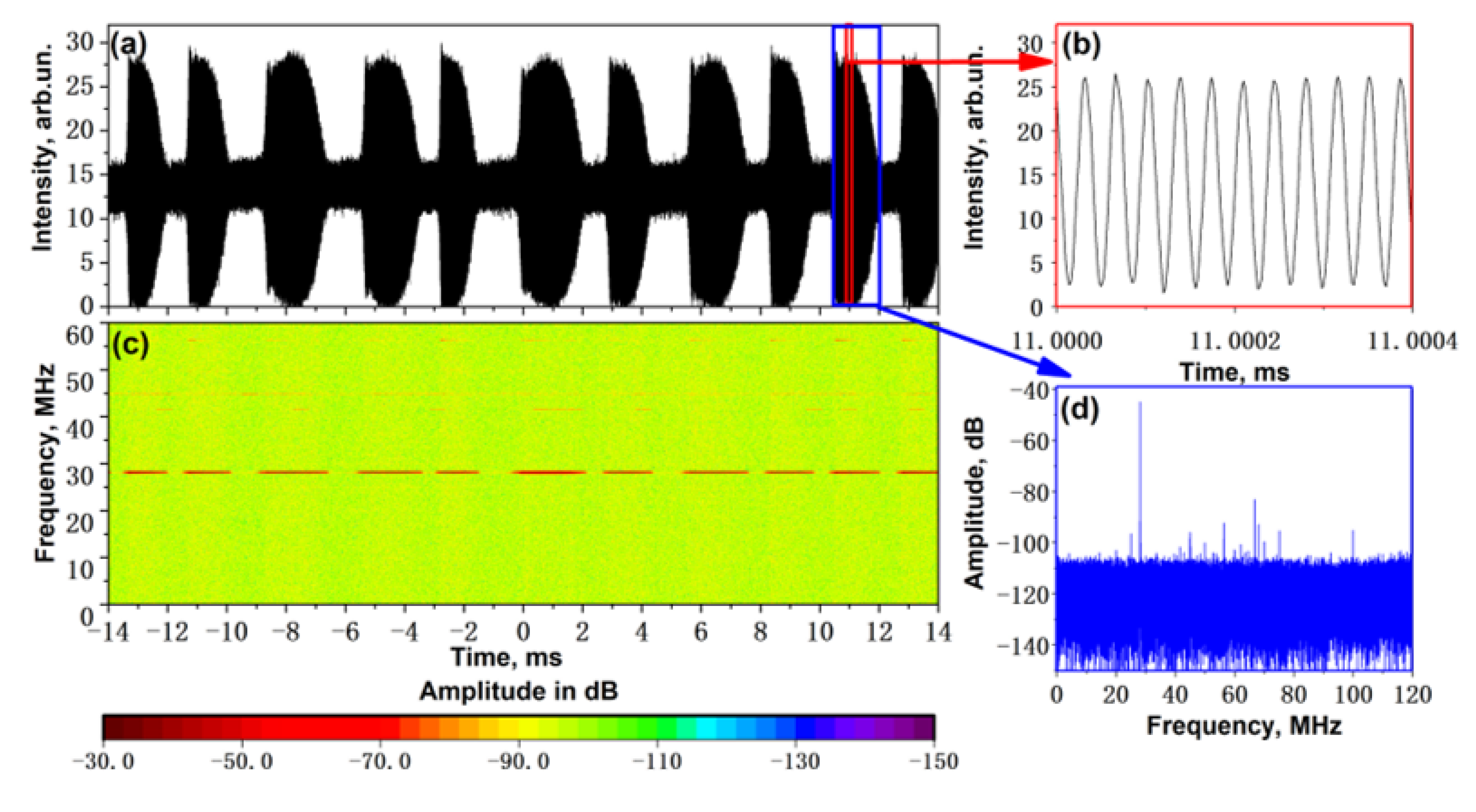
Typical intensity dynamics measured at a pump power of 740 mW are presented in Figure 7a. Figure 7a shows that intervals of small intensity fluctuations are periodically altered by intervals of large intensity fluctuations (by so-called bursts [16]). Figure 7b shows that the large intensity fluctuations have a harmonic character, corresponding to the generation of two longitudinal modes separated by 28.1 MHz. The Fourier transform (radio-frequency) spectrum (Figure 7d) calculated within the burst region, which is highlighted by the blue rectangle in Figure 7a, confirms the presence of the only high-intensity peak, confirming a double-frequency generation regime in this interval.
The measured time dependence of the signal intensity (Figure 7a) was also analyzed using a windowed Fourier transform (Figure 7c). The window width was chosen to be 4.1 µs. The result of the windowed Fourier transform is a spectrogram (radio frequency spectrum temporal dependence) demonstrating temporal variations in the mode’s composition. A comparison of the original intensity dynamics (Figure 7a) and its spectrogram (Figure 7c) shows that intermode beatings are present only during the burst intervals, confirming that single-frequency radiation is generated between the bursts. The generated modes change in the burst regions, and the intensity beatings appear in the spectrogram at the intermode beating frequency of 28.1 MHz corresponding to the triple free spectral range (FSR) of the laser cavity. It can also be found in Figure 7c that less intense intermode beating peaks are also seen in the first half of the burst at a frequency corresponding to six FSRs (see also a small peak at 56.8 MHz frequency in Figure 7d). Note that the appearance of additional peaks at multiple intermode beating frequencies during the transition process of changing the generated mode was also observed in [19].
The average duration of single-frequency generation is about 1 ms, and the mode-to-mode transition time (duration of the bursts generation) does not exceed 2 ms. As the power increases, the single-frequency generation becomes shorter, and the double-frequency bursts begin to occur more frequently. Nevertheless, the mode-to-mode transition time reduces with increase in power, and neighboring regions of the two-frequency bursts’ generation begin to overlap at pump powers above 815 mW. The laser starts to operate in a dual-longitudinal-mode self-sweeping regime with the appearance of triple-frequency bursts. The dual-longitudinal-mode self-sweeping regime was observed earlier in an Er-doped fiber laser with a linear cavity [13].

4. Discussion

An opportunity to control the operating parameters in a laser can have high practical importance in applications requiring certain generation regimes. Examples of the most interesting regimes are stable single-frequency generation, single-frequency self-sweeping, and self-sweeping with the largest tuning range. It should be noted that control of the self-sweeping laser characteristics has already been demonstrated in a number of works. For example, the possibility of switching from the self-sweeping to the wavelength stopping regime was demonstrated in Tm-doped self-sweeping fiber lasers with a certain change in the pump wavelength and/or pump power (see review [9] and references therein). The authors of these papers associated this behavior with a change in the pump absorption inhomogeneity along the active fiber. Arguing in terms of dynamic gratings, we can say that the switching the wavelength dynamics was associated with the variation in the DGG’s and DAG’s relative influence. It was shown later in [16] that it is also possible to switch between the stabilization and the wavelength self-sweeping regime by increasing the pump power and/or lengthening the absorbing fiber responsible for the DAG in the linear part of a ring cavity. It should be noted that changing the pump laser wavelength or length of a fiber in a laser cavity is not always convenient for prompt control of the laser generation regime. One of the options for controlling the laser parameters while maintaining the cavity scheme is to introduce additional controlled losses. For example, in [20,21], it was shown that by changing the intracavity losses it is possible to control the tuning range of a self-sweeping laser. However, in these works, no transitions to stabilization or single-frequency self-sweeping regimes were reported.
The experimental results of our work demonstrate that by changing the optical losses in the cavity and the pump power, it is possible to control the lasing regime of a self-sweeping laser. Moreover, it is possible to achieve the single-frequency self-sweeping regime at certain power and loss adjustments. This possibility primarily results from used laser configuration, in which the processes of the DAG and DGG formation are separated in space in the linear and ring parts of the cavity, respectively. The DAG and DGG are responsible for operating the optical frequency stabilization and for laser frequency dynamics, respectively. It is also known that efficiency of the dynamic gratings’ recording depends on the relative intensities of two counterpropagating waves. The maximum efficiency is achieved if the input intensities of both waves are equal. The input intensities become different when the generating radiation passes from the linear to the ring part of the cavity due to the 30/70 coupling ratio of the used coupler. Without introducing additional losses, the influence of the DGG on the wavelength dynamics turns out to be weak. In this case, the DAG has a larger influence on the laser optical frequency, and a single longitudinal mode stabilization is observed. We can equalize the amplitudes of the counterpropagating waves at both ends of the amplifying fiber by introducing additional losses at the output of the 70% port of the coupler and thus increase the efficiency of the DGG formation. In this way, we increase the influence of the DGG, which results in the WSSE. At intermediate losses, we observe an intermediate result of these two gratings’ competing influences.
It should be noted that the DGG amplitude can be controlled in our cavity configuration, for example, by varying the coupling ratio of the central coupler, which usually requires either replacing the coupler itself or using an expensive adjustable coupler. The use of the PZF in our scheme gives us the following possibilities: (1) polarization selection of generated radiation and (2) a relatively simple adjustment of the intracavity losses by bending a short section of the PZF. The losses introduced near the gain fiber allow for varying relative amplitudes of counter propagating waves inside the active fiber and corresponding DGG recording efficiency. Here, we show that both of these two possibilities can be achieved with a short piece (80 cm long) of the PZF. Controlling the bending of a short section of the PZF appears to be a simpler procedure than winding the fiber onto a spool with larger diameter. It should be noted that replacing the PZF with a conventional fiber attenuator will require an additional polarizing element in the cavity (for example, either adding a polarization beam splitter or using polarizing couplers in the laser cavity instead of fused ones).
The advantages of the proposed scheme also Ide the absence of optical isolators (as well as circulators) inside the cavity. An optical isolator used at the output of the laser is a necessary element to eliminate the influence of possible reflections from the measuring equipment on the laser generation regime. As a rule, such optical isolators are used in all laser schemes, regardless of their cavity design.
The single-frequency self-sweeping regime has previously been demonstrated in other schemes: in a linear scheme with pulsed generation [9] (Figure 1a) and in a ring unidirectional scheme with CW generation [16] (Figure 2a). Table 1 compares some characteristics (self-sweeping range, self-sweeping rate, pulse duration and peak output power) which have already been demonstrated in previous works on single-frequency self-sweeping fiber lasers [12,14,16,22,23,24]. It should be noted that for an Er-doped fiber laser with a single-frequency self-sweeping regime, the wavelength tuning range did not previously exceed 40 pm [16]. In our new configuration, a self-sweeping range of 2.6 nm is achieved, which is a record to date. Such radiation sources are important for practical applications. In particular, they can improve the spatial resolution of an optical frequency domain reflectometer based on a self-sweeping laser by two orders of magnitude [25]. It should be noted that the lasers operating in a pulsed regime have higher peak powers (reaching the watt level) compared to the CW ones (a few milliwatts). The generated power reported in this work is an order of magnitude lower as compared with previously demonstrated self-sweeping Er-doped laser [16]. A smaller output power can be connected with a smaller emission cross-section at 1604 nm in comparison to 1560 nm. Further research to increase the output power can be directed to optimizing the output coupling ratio. However, it should be noted that in several tasks, such as remote sensing, the energy of a single pulse is more important instead of the peak power. The pulse energies generated at a fixed optical frequency for the most single-frequency self-sweeping lasers do not differ significantly (~1–3 µJ).
5. Conclusions

In conclusion, the presented new cavity scheme for self-sweeping fiber lasers allows one to control amplitudes of standing waves in ring and linear parts of the laser cavity. Experimental implementation of the cavity scheme in an Er-doped fiber laser allowed us to demonstrate the switching between single longitudinal mode stabilization and wavelength self-sweeping regimes by controlling intracavity losses in the ring part of the cavity. Moreover, the proposed scheme does not require the presence of special isolating elements inside the laser cavity, which also makes it less expensive and more robust. The optimization of the pump power and intracavity bending losses in the described cavity configuration allowed us to demonstrate a record sweeping range of 2.6 nm at a standard telecommunication wavelength of 1604 nm in a single-frequency self-sweeping regime with CW intensity dynamics. It is expected that the developed single-frequency self-sweeping fiber source can increase the spatial resolution of optical frequency domain reflectometry by two orders of magnitude [25].

Author Contributions

Conceptualization, I.A.L. and S.I.K.; methodology, E.K.K. and S.I.K.; validation, E.K.K., I.A.L. and S.I.K.; investigation, E.K.K.; data curation, E.K.K.; writing—original draft preparation, E.K.K.; writing—review and editing, E.K.K., I.A.L. and S.I.K.; funding acquisition, I.A.L. and S.I.K. All authors have read and agreed to the published version of the manuscript.

Funding

This work was carried out as a part of the state assignment, state registration no. 122031600174-5.

Institutional Review Board Statement

Not applicable.

Informed Consent Statement

Not applicable.

Data Availability Statement

Not applicable.

Acknowledgments

The equipment of the Center for Collective Use “High Resolution Spectroscopy of Gases and Condensed Matters” at the Institute of Automation and Electrometry was used in this work.

Conflicts of Interest

The authors declare no conflict of interest.

References

  1. Fu, S.; Shi, W.; Feng, Y.; Zhang, L.; Yang, Z.; Xu, S.; Zhu, X.; Norwood, R.A.; Peyghambarian, N. Review of recent progress on single-frequency fiber lasers. J. Opt. Soc. Am. B 2017, 34, A49. [Google Scholar] [CrossRef]
  2. Wandera, C. Fiber Lasers in Material Processing. In Fiber Laser; InTech: London, UK, 2016. [Google Scholar]
  3. Lee, B. Review of the present status of optical fiber sensors. Opt. Fiber Technol. 2003, 9, 57–79. [Google Scholar] [CrossRef]
  4. Addanki, S.; Amiri, I.S.; Yupapin, P. Review of optical fibers-introduction and applications in fiber lasers. Results Phys. 2018, 10, 743–750. [Google Scholar] [CrossRef]
  5. Liu, Y.; Zhang, W.; Xu, T.; He, J.; Zhang, F.; Li, F. Fiber laser sensing system and its applications. Photonic Sens. 2011, 1, 43–53. [Google Scholar] [CrossRef] [Green Version]
  6. Babin, S.A.; Kablukov, S.I.; Vlasov, A.A. Tunable fiber Bragg gratings for application in tunable fiber lasers. Laser Phys. 2007, 17, 1323–1326. [Google Scholar] [CrossRef]
  7. Kwon, Y.S.; Ko, M.O.; Jung, M.S.; Park, I.G.; Kim, N.; Han, S.P.; Ryu, H.C.; Park, K.H.; Jeon, M.Y. Dynamic sensor interrogation using wavelength-swept laser with a polygon-scanner-based wavelength filter. Sensors 2013, 13, 9669–9678. [Google Scholar] [CrossRef] [PubMed] [Green Version]
  8. Zhao, Q.; Pei, L.; Wu, L.; Ning, T.; Zheng, J.; Li, J. Wide tuning range and high OSNR self-seeded multi-wavelength brillouin–erbium fiber laser based on a Lyot filter. Appl. Opt. 2018, 57, 10474–10479. [Google Scholar] [CrossRef] [PubMed]
  9. Poddubrovskii, N.R.; Drobyshev, R.V.; Lobach, I.A.; Kablukov, S.I. Fiber lasers based on dynamic population gratings in rare-earth-doped optical fibers. Photonics 2022, 9, 613. [Google Scholar] [CrossRef]
  10. Antsiferov, V.V.; Pivtsov, V.S.; Ugozhaev, V.D.; Folin, K.G. Spike Structure of the Emission of Solid-State Lasers. Sov. J. Quantum. Electron 1973, 3, 211–215. [Google Scholar] [CrossRef]
  11. Peterka, P.; Navrátil, P.; Maria, J.; Dussardier, B.; Slavik, R.; Honzatko, P.; Kubeček, V. Self-induced laser line sweeping in double-clad Yb-doped fiber-ring lasers. Laser Phys. Lett. 2012, 9, 445–450. [Google Scholar] [CrossRef] [Green Version]
  12. Lobach, I.A.; Kablukov, S.I.; Podivilov, E.V.; Babin, S.A. Self-scanned single-frequency operation of a fiber laser driven by a self-induced phase grating. Laser Phys. Lett. 2014, 11, 045103. [Google Scholar] [CrossRef]
  13. Kashirina, E.K.; Lobach, I.A.; Kablukov, S.I. Dual-longitudinal-mode CW self-sweeping operation in Er-doped fiber laser. Opt. Lett. 2020, 45, 6659. [Google Scholar] [CrossRef] [PubMed]
  14. Wen, Z.; Wang, K.; Chen, H.; Lu, B.; Bai, J. Self-sweeping ytterbium-doped fiber laser based on a fiber saturable absorber. Appl. Phys. Express 2021, 14, 012005. [Google Scholar] [CrossRef]
  15. Cheng, Y.; Kringlebotn, J.T.; Loh, W.H.; Laming, R.I.; Payne, D.N. Stable single-frequency traveling-wave fiber loop laser with integral saturable-absorber-based tracking narrow-band filter. Opt. Lett. 1995, 20, 875. [Google Scholar] [CrossRef] [Green Version]
  16. Poddubrovskii, N.R.; Lobach, I.A.; Kablukov, S.I. Regular mode-hopping dynamics in Erbium-doped ring fiber laser with saturable absorber. Opt. Laser Technol. 2022, 156, 108568. [Google Scholar] [CrossRef]
  17. Emslie, C. Chapter 8—Polarization Maintaining Fibers. In Specialty Optical Fibers Handbook; Méndez, A., Morse, T.F., Eds.; Academic Press: Cambridge, MA, USA, 2007; pp. 243–277. [Google Scholar]
  18. Thorlabs. Available online: https://www.thorlabs.com/newgrouppage9.cfm?objectgroup_id=6100 (accessed on 9 June 2023).
  19. Poddubrovskii, N.R.; Lobach, I.A.; Podivilov, E.V.; Kablukov, S.I. Time-resolved mode analysis in Er-doped self-sweeping ring fiber laser. Laser Phys. Lett. 2022, 19, 125102. [Google Scholar] [CrossRef]
  20. Lobach, I.A.; Tkachenko, A.Y.; Kablukov, S.I. Optimization and control of the sweeping range in an Yb-doped self-sweeping fiber laser. Laser Phys. Lett. 2016, 13, 045104. [Google Scholar] [CrossRef]
  21. Wang, K.; Wen, Z.; Chen, H.; Lu, B.; Bai, J. Wavelength-flexible all-polarization-maintaining self-sweeping fiber laser based on intracavity loss tuning. Chin. Opt. Lett. 2021, 19, 041401. [Google Scholar] [CrossRef]
  22. Kashirina, E.K.; Lobach, I.A.; Kablukov, S.I. Single-frequency self-sweeping Nd-doped fiber laser. Opt. Lett. 2019, 44, 2252. [Google Scholar] [CrossRef]
  23. Lobach, I.A.; Kablukov, S.I.; Melkumov, M.A.; Khopin, V.F.; Babin, S.A.; Dianov, E.M. Single-frequency Bismuth-doped fiber laser with quasi-continuous self-sweeping. Opt. Express 2015, 23, 24833. [Google Scholar] [CrossRef]
  24. Budarnykh, A.E.; Vladimirskaya, A.D.; Lobach, I.A.; Kablukov, S.I. Broad-range self-sweeping single-frequency linearly polarized Tm-doped fiber laser. Opt. Lett. 2018, 43, 5307. [Google Scholar] [CrossRef] [PubMed]
  25. Poddubrovskii, N.R.; Lobach, I.A.; Kablukov, S.I. Signal Processing in Optical Frequency Domain Reflectometry Systems Based on Self-Sweeping Fiber Laser with Continuous-Wave Intensity Dynamics. Algorithms 2023, 16, 260. [Google Scholar] [CrossRef]
Figure 1. Laser configurations with WSSE based on DGG: (a) Fabry–Perot-type linear laser, (b) bidirectional ring laser.
Photonics 10 00843 g001
Figure 2. Configurations of lasers with a WSSE based on DAG. Unidirectional ring cavity with a standing wave in the linear part based on: (a) circulator and (b) fiber coupler and optical isolator.
Photonics 10 00843 g002
Figure 3. The scheme of a ring Er-doped fiber self-sweeping laser using DGG and DAG.
Photonics 10 00843 g003
Figure 4. Dependence of the output power on the pump power (a) without additional losses and (b) at the maximum bending of the PZF.
Photonics 10 00843 g004
Figure 5. (a) Decrease in output generation power with increasing insertion bending loss (black rhombuses) at a fixed pump power of 780 mW. The captions in the figure indicate the stabilized/self-sweeping regime observed at the corresponding points. The temporal dependence of the generation wavelength for different cases: (b) in the absence of bending losses; (c) in the mixed regime; (d) in the self-sweeping regime.
Photonics 10 00843 g005
Figure 6. Dynamics of the laser wavelength with additional losses at a pump power of 740 mW.
Photonics 10 00843 g006
Figure 7. (a) Intensity dynamics of the generated radiation at a pump power of 740 mW; (b) a detailed view of the area highlighted by the red rectangle; (c) Fourier spectrogram of the entire time dependence of the intensity; (d) Fourier spectrum in the burst region from the interval highlighted by the blue rectangle.
Photonics 10 00843 g007
Table 1. Characteristics comparison for demonstrated single-frequency self-sweeping fiber lasers.
Wavelength, nmSweeping Range, nmSweeping Rate, nm/sPulse Duration, µsPeak Output Power, mWPulse Energy, µJRegimeReference
Er16042.60.0825001.12.75CWThis work
Er15600.020.0430002266CW[16]
Yb10684.80.2440041.6CW[14]
Yb1070204215003pulse[12]
Nd10641.89119001.9pulse[22]
Bi1460100.7552001pulse[23]
Tm19202610213002.6pulse[24]
Disclaimer/Publisher’s Note: The statements, opinions and data contained in all publications are solely those of the individual author(s) and contributor(s) and not of MDPI and/or the editor(s). MDPI and/or the editor(s) disclaim responsibility for any injury to people or property resulting from any ideas, methods, instructions or products referred to in the content.