Abstract
This paper presents a modified Bidirectional Reflectance Distribution Function (BRDF) model based on the Cauchy–Lorentz distribution that accurately characterizes the reflected energy distribution of typical materials, such as metals and coatings in hemispherical space. The proposed model overcomes the problem of large errors in classical models when detecting angles far away from the specular reflection angle by dividing the reflected light into specular reflection, directional diffuse reflection, and ideal diffuse reflection components. The newly added directional diffuse reflection component is represented by the Cauchy–Lorentz distribution, and its parameters are directly obtained from experimental measurement curves without distribution fitting. Surface morphology and model parameters are determined through measurements, and the comparison between simulation and actual measurement results shows that the modified BRDF model is in excellent agreement with the measured data. The proposed model not only achieves higher accuracy and universality, but it also represents a significant advancement in the field of BRDF modeling research. Its contributions have profound implications for advancing the state of the art in BRDF modeling, as well as having a broader impact on computer graphics and computer vision domains.
1. Introduction
In the real world, most surfaces are not perfectly smooth or polished. Instead, they are a collection of irregularities that cause light to scatter in various directions, though some directions are often favored over others. A smooth surface only reflects light in the specular direction, while a rough surface exhibits diffuse behavior due to diffraction caused by these irregularities [1]. To characterize the reflective properties of a material, it is necessary to define a function that determines the distribution of the reflected radiation based on the distribution of the incident radiation. This function is known as the Bidirectional Reflection Distribution Function (BRDF). BRDF theory has significant applications in many fields, including optical remote sensing [2,3,4], object detection and identification [5,6,7], measuring scattering and radiation at infrared and visible wavelengths for material diagnosis [8,9], and environmental monitoring [10,11]. It has also been extended to cover emerging research areas, such as 3D target reconstruction [12,13], animation [14,15], virtual reality [16,17], and computer vision [18,19].
BRDF models can be categorized into two main types [20]: empirical and analytical models. Empirical models are based on experimental data and prior experience, while analytical models rely on a first-principles approach. Typically, most models are semi-empirical in nature, meaning they combine elements of both approaches. Moreover, analytical models include physical optics models and geometric optics models, where the geometric optics model is a mathematical formula derived from the statistical properties of the actual uneven surface’s microscopic geometric structure. According to the microfacet theory, the surface is composed of many small microfacets, and the surface roughness is determined based on the distribution of the microfacet normals. The general geometric optical model assumes that the surface is composed of small surface elements tangent to the surface, each of which follows the Fresnel reflection law. Therefore, the light scattering properties of a random rough surface are the statistical result of light scattering from all small surface elements or microfacets.
One of the most classic microfacet BRDF models was proposed by Torrance and Sparrow (T-S model). Their model can be expressed as a linear combination of two terms: specular and diffuse reflection [21,22]. The term specular reflection is related to the Fresnel reflection function of the surface, the masking function, and the distribution function of the small surface elements. The diffuse reflection term is assumed to obey Lambert’s scattering law. Other microfacet BRDF models have also been developed, such as the Cook–Torrance [23], Alternate Torrance–Sparrow [24], Priest Microfacet (unpolarized) [25,26], Ward–Duer [27,28], Wellems [29], five-parameter statistical [30], and the seven-parameter models [31], which can calculate the reflection of surfaces with certain properties. Collectively, the microfacet BRDF models provide distinct mathematical representations of surface reflection, with each model exhibiting its own set of advantages and limitations. By selecting an appropriate BRDF model based on the surface properties and the desired level of accuracy, the reflective characteristics of diverse surfaces can be efficiently analyzed and simulated. However, previous studies predominantly assumed that the diffuse reflection component within the BRDF model adheres to Lambert’s law, resulting in significant errors between the viewing angle and specular reflection angle. To address this issue, our research group developed a novel three-component BRDF model that is referred to as the T-C model. This model effectively decomposes the diffuse scattering into directional diffuse and ideal diffuse components [32,33]. The introduction of the T-C model represents a significant advancement in terms of accurately capturing the complex reflectance behavior of surfaces, ensuring improved fidelity and realism in rendering and simulation applications.
Existing studies of BRDF models predominantly focused on specific types of metals or coating materials, limiting their general applicability to diverse surfaces. In this paper, our aim is to overcome this limitation by characterizing the surface properties of typical metals and satellite coatings. We analyze the interaction process between light and objects, facilitating a comprehensive understanding of surface reflectance behavior. To achieve this goal, we propose an innovative approach that utilizes the Cauchy–Lorentz distribution to characterize the directional diffuse component of the BRDF model. This unique parameterization enables direct estimation of model parameters from experimental data, eliminating the need for complex fitting procedures. This inversion of optimal model parameters is accomplished using the simulated annealing algorithm, ensuring an accurate representation of surface reflectance characteristics. Experimental results demonstrate the superior performance and general applicability of the proposed model than of classical models. It exhibits higher accuracy in fitting metal and coating BRDF measurements, overcoming the limitations of existing approaches. By providing a more comprehensive and accurate characterization of surface reflectance, this study contributes to the advancement of BRDF modeling and encourages its practical application in various domains.
2. Materials and Methods
2.1. Modeling of BRDF
The BRDF characterized the distribution of reflected energy in the hemisphere [34], offering a quantitative description of the ways in which light is reflected from a surface.
In this equation, θi and θr denote the angles between the incident and reflected beams and the surface normal, respectively, and φi and φr denote the azimuthal angles of the incident and reflected beams, respectively. Radiance L is the radiant power flow per unit solid angle and unit area normal to the rays, and it has units of [W/m2·sr], while irradiance E is the power flux density that irradiates a surface per unit area of the surface, and it has units of [W/m2]. The geometry of the incident and reflected beams is shown in Figure 1.
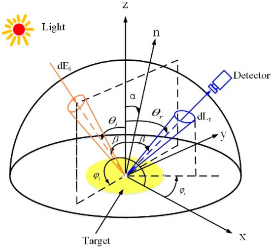
Figure 1.
Geometric illustration of angle variables for description of a BRDF.
We studied the physical mechanism of the interaction between light and the object and divided the reflected light into three components: specular, directional diffuse, and ideal diffuse reflection. The interaction between light and the object is illustrated in Figure 2.
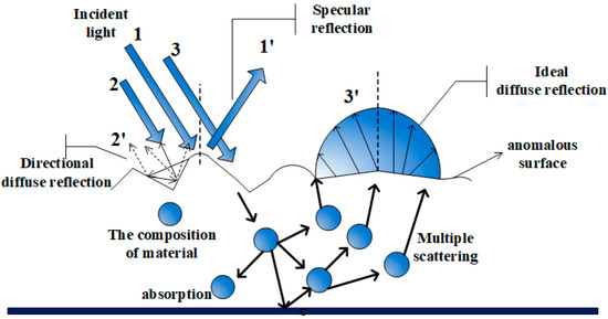
Figure 2.
The interaction between light and the object.
Specular reflection, directional diffuse reflection, and ideal diffuse reflection are represented by the variables fs, fdd, and fid, respectively. The reflection characteristics of a material are influenced by the type of material and the incident conditions, which means that the proportional coefficients ks, kdd, and kid of the three reflection effects could not be determined through direct calculation. Instead, these coefficients had to be obtained through experimental measurement. Therefore, the BRDF expression reads
We used the Torrance–Sparrow model, which is based on the geometric optics method and the microfacet theory, to describe the specular reflection component. This model satisfies Snell’s law of reflection and assumes that the slope of the microfacet follows a random Gaussian distribution. We assumed that α represents the angle between the macroscopic surface normal Z and the microfacet normal n, β represents half the angle between the incident and reflection directions, and σ represents the surface roughness. According to the Torrance–Sparrow BRDF model, the specular reflection component fs could be expressed as follows:
where is the Fresnel reflectivity, is the microfacet area per unit area, is the slope distribution function of the microfacet, and G is the geometric attenuation of reflected light caused by the shadowing and shading effect that occurs between adjacent microfacets.
The directional diffuse reflection was formed when light bounces off the uneven surface of a sample multiple times. Due to the complexity of this process, there was no complete mathematical expression for describing multiple reflections. However, Wang found, in his experiments, that the spatial distribution of multiple reflected light beams from metal materials is Gaussian in nature [32], and he proposed an empirical expression for the BRDF, as shown in Equation (5). Similarly, Liu observed that the distribution of directional diffuse-reflected light has the characteristics of a high cosine function [33], which is similar to the Phong model [35]. By fitting the coating material, he proposed an expression of the multiple reflected component as a high cosine function on the reflection angle, as shown in Equation (6).
where the parameter and n are acquired via fitting with the experimental data.
In this study, the Cauchy–Lorentz distribution, which is often used in the analysis of spectral curves, was utilized to fit and describe the directional diffuse reflectance. The BRDF expression is given as:
where is the scale parameter of half width at half the maximum value. The parameter was distinct from , and n and did not require the use of an algorithm to fit the parameters suitable for a specific type of sample, such as metal or coating. It represented half of the half-wave width of the actual spectral line and can be directly obtained via the experimental data curve. This feature made the whole BRDF model more versatile and widely applicable to a variety of target materials. Furthermore, by adjusting other parameters of the model, we could analyze the physical meaning of and its impact on the overall BRDF expression.
Ideal diffuse reflection occurred when the beam entered the subsurface of the sample and penetrated the surface after interacting with the interior material. This component’s spatial distribution was uniform throughout the entire hemisphere. Therefore, fid was a constant:
2.2. BRDF Experimental Measurement
2.2.1. Sample Surface Characterization
The surface topographies of four materials, namely Al, Cu, satellite-coating material SR107, and S781, were measured using the LEXT OLS4000 produced via OLYMPUS. The LEXT OLS4000 employed a laser light source that was meticulously focused on the sample surface using an objective lens. The collected light reflected from the sample was then directed through a confocal pinhole before reaching a detector. This confocal configuration enabled the instrument to conduct precise measurements of surface topography by selectively capturing the light originating solely from the focal plane. Consequently, it significantly enhanced imaging quality and facilitated the accurate reconstruction of the three-dimensional morphology of the sample. In this paper, we utilized the LEXT OLS4000 to accurately assess the surface roughness and topography of the target material. The surface roughness values for Al, Cu, SR107, and S781 were 0.142 μm, 0.070 μm, 0.206 μm, and 0.116 μm, respectively. The device and the four materials are depicted in Figure 3a,b.
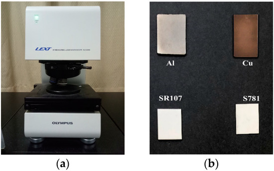
Figure 3.
Laser confocal microscope and typical materials: (a) LEXT OLS4000; (b) metal and coating samples.
2.2.2. Experiment Device
The experimental setup, as shown schematically in Figure 4 and Figure 5, comprised a 632.8 nm He–Ne laser, a S130C photodiode power meter head and PM100A analog handheld laser power meter head acquired from Thorlabs, a measurement dial, and a control unit. The experiment was conducted in a darkroom environment to minimize the error caused by stray light. As the laser light source instrument was relatively complex and precise, the light source was fixed during the experiment, and the control system rotated the tested sample and the detector. The distance between the illumination and detection points used in the measured sample were kept constant at different angles. The light source was irradiated perpendicularly to the sample surface, and the rotating detector received the light reflected by the sample surface in the range of −80 to 80°. The sample was rotated 10° clockwise, and the detector repeated the above steps until the reflected light distribution of the entire incident surface at different incident angles from 0 to 80° was obtained.
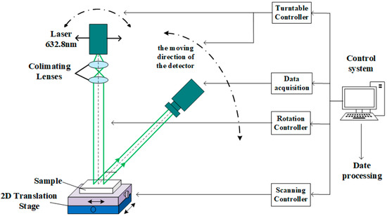
Figure 4.
Schematic view of the BRDF measurement.
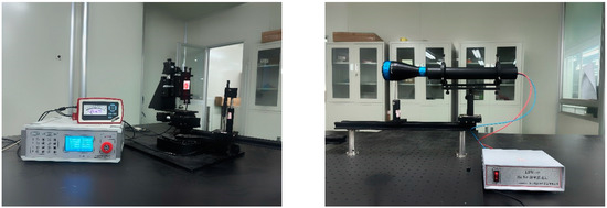
Figure 5.
Measuring equipment of the BRDF.
Firstly, we validated our measurement equipment by measuring the reflectance of a standard aluminum sheet with a specular surface and measuring the BRDF of a standard whiteboard with a Lambertian surface. We used the relative root mean square error (RMSE δ) to quantify the deviation of our results from the theoretical value. The δ parameter is defined as follows:
in which fmeasured denotes the measured data, and f theoretical denotes the theoretical value.
As can be seen from the comparison between the measured results and the theoretical values shown in Figure 6 and Figure 7, the error δ of our equipment was very small, being less than 0.06% for specular reflection and 0.75% for Lambert’s reflection. In Figure 7, the selection of BRDF·cosθr as the ordinate was derived from Equation 10, which started with the definition of BRDF. By substituting the definitions of irradiance and radiance into the BRDF formula, considering a fixed light source with a constant incident light intensity, there existed a cosine coefficient between the BRDF value and the light intensity measured using the detector. This choice allows accurate representation of the relationship between the BRDF value and the detector’s light intensity. These results demonstrate that our measurement equipment is highly accurate and reliable.
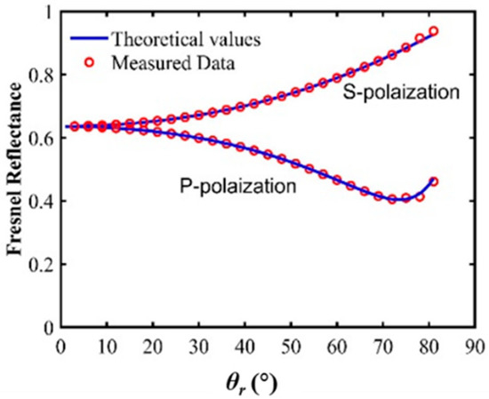
Figure 6.
Verification of specular reflection.
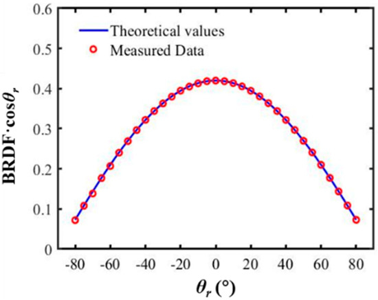
Figure 7.
Verification of Lambert’s reflection.
3. Results
Using the Simulated Annealing Algorithm (SAA), we implemented the model parameters. SAA is a random search algorithm based on the Monte Carlo iterative calculation method and can find the global optimal solution during simulated annealing. In this study, optimization is the process of finding the minimum or maximum solution to the objective function in the solution space. The optimization criterion for selecting model parameters is to minimize the standard mean square error between the simulated and measured data [36]. The objective function is defined as follows:
where x = [ks, kdd, kid]T represents the column vector; ks, kdd, and kid are the empirical parameters of the model; represents the measured BRDF data, and represents the calculated BRDF data. The weight functions and adjust the influence of each error on the total error when the measurement distance is uneven. The selection of the weighting function depends on the purpose of modeling and the accuracy of measurement of uneven distances. The detailed algorithm process can be found in Appendix A. In this study, the experimental data are measured at equal intervals of 1. The parameter is obtained by calculating its half-wave width from the experimental curve. The best fit values for both metal samples are found to be 𝑘dd = 75,630, 𝑘id = 24, and = 47, while for both coating samples, the best fit values are 𝑘dd = 33,900, 𝑘id = 24, and = 74. These findings suggest that the multiple reflection and volume scattering values remain constant for different incident angles θi. The coefficient of the specular component 𝑘s increases with θI, as listed in Table 1.

Table 1.
The values of the 𝑘s of the four samples in different incident angles.
Thus, the complete expression of the BRDF models for metal materials and coating materials can be written as:
Figure 8 illustrates the top view of the simulated 3D BRDF for the four samples with θi = 40°. The metal materials, such as Al and Cu, display sharper specular peaks than the coatings, such as SR107 and S781, which have smoother peaks. The surface roughness also has an impact on the BRDF peak, where rough surfaces have lower peaks than smooth surfaces made from the same material. Specifically, sample Cu has a sharp peak and distinct specular reflection, while sample Al has a slightly broader peak and a more extended tail. Samples SR107 and S781 have even broader and smoother peaks, indicating less distinct specular reflection. These observations indicate that the BRDF of a surface depends on both its material and surface roughness.
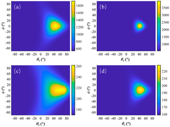
Figure 8.
Top view of four-sample-simulated 3D BRDFs with incident angles of θi = 40°: (a) Al; (b) Cu; (c) SR107; (d) S781.
Figure 9 shows the spatial distribution of BRDF values of coating SR107 in the upper hemisphere at various incident angles. The Figure 9a–d correspond to incident angles of θi= 20°, 30°, 40°, and 50°, respectively. The top view of the hemisphere illustrates the variations in BRDF values with respect to the incident angle. Specifically, as the incident angle increases, a peak near the angle that is greater than the specular reflection angle becomes apparent, which can be attributed to the presence of shadow occlusion factors, a finding that is consistent with the commonly observed off-specular reflection peak phenomenon in experiments. This visual representation of the simulation model can be applied to remote sensing detection, such as space detection.
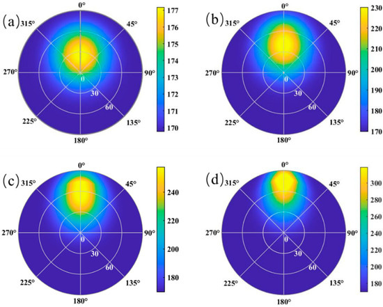
Figure 9.
Spatial distribution of the BRDF value of coating SR107 in the upper hemisphere under different incident angles: (a) θi = 20°; (b) θi = 30°; (c) θi = 40°; (d) θi = 50°.
As shown in Figure 8 and Figure 9, our model exhibits azimuthal symmetry. Therefore, to verify the Cauchy–Lorentz modified BRDF model proposed in this paper, we chose to test it at incident angles of 30°, 40°, and 50° when the azimuth angle is equal to π. Figure 10 and Figure 11 compare the measured BRDF data of the four samples with the simulation results of the T-S model, the T-C model, and the model proposed in this paper. It should be noted that f/f(θi) values in the graph are normalized with respect to their values at the specular angle (θi = θr).
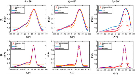
Figure 10.
Simulated and measured BRDFs of metal samples: (a) Al; (b) Cu.
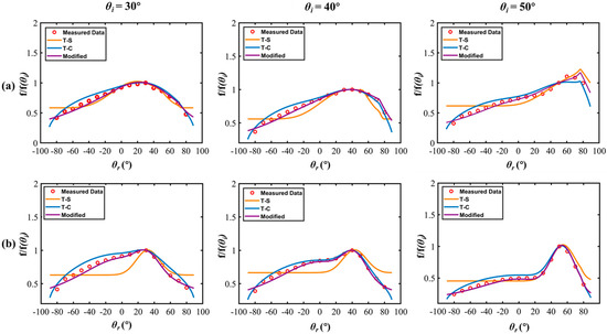
Figure 11.
Simulated and measured BRDFs of coating samples: (a) SR107; (b) S781.
In Figure 10, we compare the simulated and measured BRDFs of two metal samples: Al and Cu. It can be observed that the classical T-S model exhibits large errors in regions where the reflection angle deviates significantly from the specular angle. This outcome occurs because the T-S model assumes that the diffuse reflection component follows Lambert’s law, which is not always accurate in practice. In contrast, our proposed Lorentz–Cauchy modified model shows excellent agreement with the experimental results of the two samples, exhibiting higher accuracy than the T-C model proposed by Wang [32].
Figure 11 shows the simulated and measured BRDF of two coating samples: SR107 and S781. Compared to metal materials, coating materials exhibit a flatter BRDF distribution, which is consistent with the fact that real-world coating materials tend to reduce the specular component of surface reflection. The T-S model, which neglects directional reflection, shows significant errors when the reflection angle deviates far from the specular angle, especially for the S781 coating sample, where the error is particularly large. In contrast, our proposed Lorentz–Cauchy modified model provides a better fit for the experimental results of both samples and exhibits higher accuracy than the T-C model proposed by Liu [33].
As shown in Figure 10 and Figure 11, the observed differences in the BRDF values between Al and Cu, as well as between SR107 and S781, can be attributed to variations in their roughness and material properties. It is evident that the BRDF values are influenced not only by the incident and outgoing angles and the wavelength of light, but also by surface properties, such as surface roughness and microstructure. These surface properties play a crucial role in determining the scattering behavior and the resulting BRDF values. The BRDF peak becomes sharper and higher as the incident angle θi increases. This result occurs because the specular component fs reaches higher peaks at larger incident angles. Therefore, it is crucial to consider the incident angle when modeling the BRDF of a surface. The proposed modified model effectively overcomes the limitations of the conventional T-S model and accurately models the BRDF of both metal and coating materials by taking into account the directional diffuse reflection. It should be noted that the directional diffuse reflection is more pronounced when the reflection angle θr is around 0°, and it gradually weakens as the reflection angle increases. Therefore, accurate modeling of the directional diffuse reflection component is critical for characterizing the BRDF of a surface. In summary, the proposed model has the potential to enhance the accuracy of remote sensing detection, including space detection, by improving the modeling of light interaction with various surface materials.
4. Discussion
Figure 12 compares the Modified, T-C, and T-S models for the four samples at θi = 30°, 40°, and 50°. The cumulative bar graph errors for the four materials are calculated according to Equation (9), and the δ values of the three models are presented in Table 2 and Table 3. RMSE1, RMSE2, and RMSE3 represent the root mean square error between the T-S, T-C, and modified models proposed in this paper, respectively, as well as the experimental measurement values. It is evident that RMSE3 is the smallest value under the same incident angle, indicating the modified model has the highest accuracy. Percentage drops 1 and 2 indicate the increase in accuracy for the modified models compared to the T-S model and the T-C model, respectively. For all four materials, the improved model exhibited a significant increase in accuracy compared to the T-S model, ranging from 0.18 to 84.75%, with an average improvement of 57.16%. Similarly, compared to the T-C model, the improved model showed an average increase in accuracy of 30.61%, with the lowest increase being 0.54% and the highest increase being 67.41%. Therefore, our proposed Cauchy–Lorentz modified model significantly enhanced the accuracy and universality of BRDF modeling and effectively described the distribution characteristics of reflected energy for both metal and coating materials in the hemisphere.
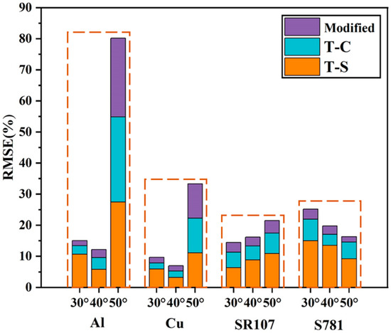
Figure 12.
Error cumulative bar chart.

Table 2.
RMSE between the three models and the measured values for metals.

Table 3.
RMSE between the three models and the measurements for the coating.
5. Conclusions
In this paper, based on the Cauchy–Lorentz distribution theory, a general three-component BRDF model is proposed for typical materials, such as metals and coatings. The model considers the specular component, which is described via the microfacet theory, as well as the directional and ideal diffuse reflectance components. The directional diffuse reflectance is obtained via the measured Cauchy–Lorentz distribution, and its parameters are directly determined by the half-wave width of the measured curve. The ideal diffuse reflectance is uniformly distributed, and the proportions of the three components are determined using the simulated annealing algorithm. The modified model, when compared to the classical T-S and T-C models, exhibits a significant reduction in error for reflection angles that are far away from the specular reflection angle, with average error reductions of 0.0551 and 0.0160, respectively. Additionally, the proposed model demonstrates improved accuracy in the hemispherical reflection surface, with average improvements of 57.16 and 30.61% compared to the T-S and T-C models, respectively. These findings highlight the superior performance of the modified model in accurately characterizing the scattering behavior in these scenarios. The model is verified experimentally, demonstrating its ability to accurately describe the reflection behavior of metal and coating surfaces in hemispherical spaces.
This paper focuses on investigating the scattering distribution characteristics of metals and coating materials at specific wavelengths, and the proposed model is validated based on typical targets. However, to broaden the scope of our research and explore its applicability under different scenarios, it is essential to quantitatively verify the model’s performance under varying boundary conditions, particularly when dealing with multiple wavelengths. Additionally, we have plans to extend our study to encompass a wider range of materials, including diffuse materials and those with multilayer structures. By conducting these investigations, we aim to gain a more comprehensive understanding of the scattering behaviors exhibited by different material types. These future research endeavors will contribute to the ongoing development and refinement of our model, enabling its practical application in various fields.
Author Contributions
Conceptualization, F.G. and J.Z.; methodology, F.G.; software, F.G.; validation, F.G., H.L. (Haoxiang Li), J.D. and X.Z.; formal analysis, F.G.; investigation, F.G.; resources, F.G.; data curation, F.G.; writing—original draft preparation, F.G.; writing—review and editing, L.H., K.W., H.L. (Hong Liu) and X.H.; visualization, F.G.; supervision, F.G.; project administration, J.Z.; funding acquisition, J.Z. All authors have read and agreed to the published version of the manuscript.
Funding
This research was funded by the National Natural Science Foundation of China, grant number 61890961; the National Natural Science Foundation of China, grant number 62127813; the Natural Science Basic Research Plan in Shaanxi Province of China, grant number 2018JM6008; and the Weinan Key Research and Development Program Project—Fundamental Research of China, grant number No. 2021ZDYF-JCYJ-274.
Institutional Review Board Statement
Not applicable.
Informed Consent Statement
Not applicable.
Data Availability Statement
All data are contained within the article.
Conflicts of Interest
The authors declare no conflict of interest.
Appendix A. Optimization Process Using Simulated Annealing Algorithm
- Objective Function:
- The objective function, which is denoted as ‘E(x)’, represents the function to be minimized;
- The input parameter x contains the coefficients that will be optimized: ‘𝑘s’, ‘𝑘dd’, and ‘𝑘id’.
- Simulated Annealing Algorithm (SAA) Parameters:
- ‘initial_temperature’: the initial temperature of the annealing process;
- ‘final_temperature’: the termination temperature at which the annealing process stops;
- ‘cooling_rate’: the rate at which the temperature decreases during the annealing process;
- ‘max_iterations’: the maximum number of iterations allowed;
- ‘tolerance’: the convergence threshold for the optimization process.
- Parameter Range:
- ‘lb’: the lower bound of the parameter range for ‘𝑘s’, ‘𝑘dd’, and ‘𝑘id’;
- ‘ub’: the upper bound of the parameter range for ‘𝑘s’, ‘𝑘dd’, and ‘𝑘id’.
- Initialization:
- Initialize the SAA with the following variables:
- ‘current_temperature’: set the initial temperature to initial_temperature;
- ‘current_solution’: randomly initialize a solution within the parameter range defined based on ‘lb’ and ‘ub’;
- ‘best_solution’: set the best solution as the current solution;
- ‘best_cost’: set the best cost as the objective function value of the current solution;
- ‘history’: an array to store the objective function values during the optimization process.
- Optimization Iterations:
- Iterate the optimization process as follows:
- Generate a new solution by perturbing the current solution based on the current temperature;
- Constrain the new solution within the parameter range defined based on ‘lb’ and ‘ub’;
- Calculate the objective function value for the new solution;
- Decide whether to accept the new solution based on the objective function value and the current temperature;
- Decrease the temperature based on the cooling rate;
- Check for termination conditions: if the temperature is below the final temperature or the objective function change is below the tolerance, stop the optimization process.
- Output:
- Display the optimal solution values for ‘𝑘s’, ‘𝑘dd’, and ‘𝑘id’ found during the optimization process;
- Display the corresponding minimum objective function value.
- Convergence Curve:
- Plot a graph showing the convergence of the objective function values over the iterations.
References
- Born, M.; Wolf, E. Principles of Optics, 2nd (revised) ed.; Pergamon Press: Oxford, UK, 1964. [Google Scholar]
- Roujean, J.L.; Leroy, M.; Deschamps, P.Y. A bidirectional reflectance model of the Earth’s surface for the correction of remote sensing data. J. Geophys. Res. 1992, 97, 20455. [Google Scholar] [CrossRef]
- Cheng, J.; Wen, J.G.; Xiao, Q.; Hao, D.L.; Lin, X.W.; Liu, Q.H. Exploring the Applicability of the Semi-Empirical BRDF Models at Different Scales Using Airborne Multi-Angular Observations. IEEE Geosci. Remote Sens. 2022, 19, 99. [Google Scholar] [CrossRef]
- Scarboro, C.G.; Doherty, C.J.; Balint-Kurti, P.J.; Kudenov, M.W. Multistatic fiber-based system for measuring the Mueller matrix bidirectional reflectance distribution function. Appl. Opt. 2022, 61, 9832–9842. [Google Scholar] [CrossRef] [PubMed]
- Wang, O.; Gunawardane, P.; Scher, S.; Davis, J. Material classification using BRDF slices. In Proceedings of the IEEE 2009 IEEE Conference on Computer Vision and Pattern Recognition (CVPR), Miami, FL, USA, 20–25 June 2009; pp. 2805–2811. [Google Scholar]
- Shi, H.D.; Liu, Y.; He, C.F.; Wang, C.; Li, Y.C.; Zhang, Y.L. Analysis of infrared polarization properties of targets with rough surfaces. Opt. Laser Technol. 2022, 151, 108069. [Google Scholar] [CrossRef]
- Jiang, C.X.; Tan, Y.; Qu, G.N.; Lv, Z.; Gu, N.W.; Lu, W.J.; Zhou, J.W.; Li, Z.W.; Xu, R.; Wang, K.L.; et al. Super diffraction limit spectral imaging detection and material type identification of distant space objects. Opt. Express 2022, 30, 46911–46925. [Google Scholar] [CrossRef] [PubMed]
- Bai, L.; Wu, Z.; Cao, Y.; Huang, X. Spectral scattering characteristics of space target in near-UV to visible bands. Opt. Express 2014, 22, 8515–8524. [Google Scholar] [CrossRef]
- Sohaib, A.; Broadbent, L.; Farooq, A.R.; Smith, L.N.; Smith, M.L. BRDF of human skin in the visible spectrum. Sens. Rev. 2017, 37, 390–395. [Google Scholar] [CrossRef]
- Otremba, Z.; Piskozub, J. Modelling the bidirectional reflectance distribution function (BRDF) of seawater polluted by an oil film. Opt. Express 2004, 8, 1671–1676. [Google Scholar] [CrossRef] [PubMed]
- Zhang, T.H.; Wang, L.C.; Zhao, B.; Gu, Y.; Wong, M.S.; She, L.; Xia, X.H.; Dong, J.D.; Ji, Y.X.; Gong, W.; et al. A Geometry-Discrete Minimum Reflectance Aerosol Retrieval Algorithm (GeoMRA) for Geostationary Meteorological Satellite Over Heterogeneous Surfaces. IEEE Trans. Geosci. Remote 2022, 60, 1–14. [Google Scholar] [CrossRef]
- Atkinson, G.A.; Hancock, E.R. Shape estimation using polarization and shading from two views. IEEE Trans. Pattern Anal. 2007, 29, 2001–2017. [Google Scholar] [CrossRef]
- Ziang, C.; Hongdong, L.; Richard, H.; Yinqiang, Z.; Imari, S. Diffeomorphic Neural Surface Parameterization for 3D and Reflectance Acquisition; ACM: New York, NY, USA, 2022; pp. 7–10. [Google Scholar]
- Weyrich, T.; Pfister, H.; Gross, M. Rendering Deformable Surface Reflectance Fields. IEEE Trans. Vis. Comput. Graph. 2005, 11, 48. [Google Scholar] [CrossRef] [PubMed]
- Sun, X.; Zhou, K.; Chen, Y.; Lin, S.; Shi, J.; Guo, B. Interactive relighting with dynamic BRDFs. ACM Trans. Graph. 2007, 26, 21–27. [Google Scholar] [CrossRef]
- Bernardini, F.; Martin, I.M.; Rushmeier, H. High-quality texture reconstruction from multiple scans. IEEE Trans. Vis. Comput. Graph. 2001, 7, 318–332. [Google Scholar] [CrossRef]
- van der Sanden, K.; Hogervorst, M.A.; Bijl, P. Hybrid simulation for creating realistic scenes for signature assessment. In Target and Background Signatures VIII; Stein, K., Schleijpen, R., Eds.; Conference on Target and Background Signatures VII; SPIE: Bellingham, WA, USA, 2022; Volume 12270. [Google Scholar]
- Gilmore, M.S.; Casta, O.R.; Mann, T.; Anderson, R.C.; Mjolsness, E.D.; Manduchi, R.; Saunders, R.S. Strategies for autonomous rovers at Mars. J. Geophys. Res. Atmos. 2002, 105, 29223–29237. [Google Scholar] [CrossRef]
- Shi, W.Q.; Dorsey, J.; Rushmeier, H. Learning-Based Inverse Bi-Scale Material Fitting From Tabular BRDFs. IEEE Trans. Vis. Comput. Graph. 2022, 28, 1810–1823. [Google Scholar] [CrossRef]
- Montes Soldado, R.A.; Ureña Almagro, C. An Overview of BRDF Models; University of Grenada: True Blue, Grenada, 2012; pp. 2–22. [Google Scholar]
- Torrance, K.E.; Sparrow, E.M.; Birkebak, R.C. Polarization, Directional Distribution, and Off-Specular Peak Phenomena in Light Reflected from Roughened Surfaces. J. Opt. Soc. Am. 1966, 56, 916–924. [Google Scholar] [CrossRef]
- Torrance, K.E.; Sparrow, E.M. Theory for Off-Specular Reflection from Roughened Surfaces*. J. Opt. Soc. Am. 1967, 57, 1105–1114. [Google Scholar] [CrossRef]
- Cook, R.L. A reflectance models for computer graphics. ACM Trans. Graph. 1982, 15, 307–316. [Google Scholar] [CrossRef]
- Schott, J.R. Fundamentals of Polarimetric Remote Sensing; SPIE Press: Bellingham, WA, USA, 2009. [Google Scholar]
- Priest, R.G.; Gerner, T.A. Polarimetric BRDF in the Microfacet Model: Theory and Measurements. In Proceedings of the Meeting of the Military Sensing Symposia Specialty Group on Passive Sensors, Washington, DC, USA, 1 March 2000; Volume 5, pp. 988–993. [Google Scholar]
- Priest, R.G.; Meier, S.R. Polarimetric microfacet scattering theory with applications to absorptive and reflective surfaces. Opt. Eng. 2002, 41, 988–993. [Google Scholar] [CrossRef]
- Ward, G. Measuring and modeling anisotropic reflection. ACM SIGGRAPH Comput. Graph. 1992, 2, 265–272. [Google Scholar] [CrossRef]
- Duer, A. An Improved Normalization for the Ward Reflectance Model. J. Graph. Gpu Game Tools 2006, 11, 51–59. [Google Scholar] [CrossRef]
- Wellems, D.; Ortega, S.; Bowers, D.; Boger, J.; Fetrow, M. Long wave infrared polarimetric model: Theory, measurements and parameters. J. Opt. A Pure Appl. Opt. 2006, 8, 914. [Google Scholar] [CrossRef]
- Zhensen, W.; Donghui, X.; Pinhua, X.; Qingnong, W. Modeling reflectance function from rough surface and algorithms. Acta Opt. Sin. 2002, 22, 897–901. [Google Scholar]
- Bai, L.; Wu, Z.; Zou, X.; Cao, Y. Seven-parameter statistical model for BRDF in the UV band. Opt. Express 2012, 20, 12085–12094. [Google Scholar] [CrossRef] [PubMed]
- Wang, K.; Zhu, J.P.; Liu, H.; Hou, X. Model of bidirectional reflectance distribution function for metallic materials. Chin. Phys. B 2016, 25, 94201. [Google Scholar] [CrossRef]
- Liu, H.; Zhu, J.P.; Wang, K.; Wang, X.H.; Xu, R. Three-Component Model for Bidirectional Reflection Distribution Function of Thermal Coating Surfaces. Chin. Phys. Lett. 2016, 33, 64204. [Google Scholar] [CrossRef]
- Nicodemus, F.E. Radiometry with Spectrally Selective Sensors. Appl. Opt. 1968, 7, 1649–1652. [Google Scholar] [CrossRef]
- Phong, B.T. Illumination for Computer Generated Pictures. Commun. ACM 1975, 18, 311–317. [Google Scholar] [CrossRef]
- Kirkpatrick, S.; Gelatt, C.D.; Vecchi, M.P. Optimization by Simulated Annealing. Science 1983, 220, 671–680. [Google Scholar] [CrossRef]
Disclaimer/Publisher’s Note: The statements, opinions and data contained in all publications are solely those of the individual author(s) and contributor(s) and not of MDPI and/or the editor(s). MDPI and/or the editor(s) disclaim responsibility for any injury to people or property resulting from any ideas, methods, instructions or products referred to in the content. |
© 2023 by the authors. Licensee MDPI, Basel, Switzerland. This article is an open access article distributed under the terms and conditions of the Creative Commons Attribution (CC BY) license (https://creativecommons.org/licenses/by/4.0/).