Article

General Astigmatism of Structured LG Beams: Evolution and Transformations of the OAM Super-Bursts

1
V.I. Vernadsky Crimean Federal University, Vernadsky Prospect 4, Simferopol 295007, Russia
2
Lebedev Physical Institute, Samara 443011, Russia
*
Author to whom correspondence should be addressed.
Photonics 2023, 10(7), 727; https://doi.org/10.3390/photonics10070727
Submission received: 9 May 2023 / Revised: 19 June 2023 / Accepted: 20 June 2023 / Published: 25 June 2023
(This article belongs to the Special Issue Recent Advances in Optical Diffraction and Imaging)

Abstract

:
We have developed a structured beams theory, computer simulation and experiment that have lost rotational symmetry and propagate in a medium with a general astigmatism. It transpires that the astigmatic medium brings to light such hidden properties of the structured beams as a sharp growing of the orbital angular momentum exceeding the sum of the radial and azimuth numbers, as well as the effect of the beam structure following the cylindrical lens rotation.

1. Inroduction

The unique properties of structured light with multiple degrees of freedom are well known; the most crucial part is played by their ability to transfer big data [1,2,3,4,5,6] and their resistibility to destruction in a turbulent atmosphere [7,8,9,10]. As a rule, random processes of the developed turbulence destroy the beam structure. The authors of ref. [8] indicate that the statistical regularities of intensity fluctuations and the orbital angular momentum (OAM) of the structured beam fluctuations mostly follow those of the already well-studied Laguerre–Gaussian (LG) beam. On the other hand, the authors in ref. [10] proposed some complex forms of structured light which are invariant under propagation through the atmosphere due to the so-called “true eigenmodes” of atmospheric turbulence. They developed a theoretical procedure for obtaining these “eigenmodes” and confirmed their invariance both numerically and experimentally. Nevertheless, even regular optical media, such as optical fibers [11] or astigmatic media [12], can significantly transform the structure of singular beams, dramatically changing their vortex composition. At the same time, it is possible to form a structured beam in such a way that an external perturbation causes a directed energy conversion between its modes in such a way that an external perturbation causes a directed energy conversion between its modes. A simple example of such a wave composition is a structured LG beam [13]. The thought behind such beam compositions is based on the fundamental structural instability of the LG modes. The fact is that the complex amplitude of a single standard LG mode can be formally represented on the basis of standard Hermite–Gaussian (HG) modes [14]. In order to transform a standard LG mode into the structured LG beam with multiple degrees of freedom, it is sufficient to bring big data into each HG mode by encoding their amplitudes and phases.
If a part of the HG modes have the same amplitude parameters ϵ , but in each HG mode the initial phases are excited (multiples of the parameter θ ) we obtain two parametric-structured LG beams, which can be mathematically represented as a sum of the standard LG mode and a hybrid Hermite–Laguerre–Gaussian (HLG) [15] mode rotated at the π / 4 angle. However, the hybrid HLG mode has the property of rotational symmetry when its properties are reproduced on the period π / 2 of the control parameter. However, its superposition with the LG mode violates the original rotational symmetry, thereby bringing to light hidden mode properties. Indeed, variations in the new phase parameter θ result in fast oscillations of the orbital angular momentum (OAM) of the structured LG beam (sLG), the amplitude of which does not exceed the azimuthal number of the HLG mode, while their frequency is specified by a radial number n [14]. At the same time, the OAM spectrum of the sLG beam covers the range from ( 2 n + ) to ( 2 n + ) , which can significantly exceed the maximum OAM amplitude of the HLG beam for arbitrary radial numbers. In fact, symmetry breaking down causes a conversion of degenerate vortices in ring dislocations of the former HLG and LG modes into real vortices of the structured sLG beam and, as a consequence, the modulation of its OAM.
Since the main attention in our article concerns converting laser beams in an astigmatic medium, we will briefly explain what the meaning of the term “astigmatic medium” is. The Greek word “astigmatism” means the lack of a single focal point, i.e., the medium focuses the light rays lying in the main perpendicular planes of the medium in different ways and they do not have a common focus, as, for example, in the case of a cylindrical lenses. For structured beams, this manifests itself in different scaling of the wavefront along the main directions of the astigmatic medium when propagating.
In order to control the amplitude of the OAM, we exposed the sLG beam to an astigmatic medium with a simple astigmatism, the role of which is performed by a cylindrical lens in the experiment. We found that fast oscillations are partially suppressed, but nevertheless the points of beam invariants [16] and superbursts of the OAM [17] occur in the condition that the astigmatic axis β of the medium is parallel to the standard HG beam symmetry axis ( β = 0 ). It is worth noting that the area of astigmatic invariance means that the beam propagates through the astigmatic medium without structured transforms only at a certain ratio θ = 2 arctan b between the astigmatic parameter b of the medium and the phase parameter θ of the sLG beam. However, due to the smoothing of fast oscillations with simple astigmatism, superbursts of the OAM occur near the critical point θ = π of the phase parameter far from the astigmatic-invariant area.
If the axis of astigmatism is rotated at an arbitrary angle β 0 [12], then the eigenmodes of the sLG beam are mixed with each other, forming states with new invariants and super OAM bursts. Thus, the purpose of our article is to develop a theory of structured sLG beams in media with a general astigmatism and to bring to light evolution of OAM superbursts while preserving a fine sLG beam structure caused by a breaking down their rotational symmetry.

2. Astigmatic Transforms of the sLG Beam

The task of our theoretical section is to obtain the complex amplitude of a multiparametric structured beam in the medium with a general astigmatism and analyze the evolution of its parameters within the framework of unitary transformations. ξ and η denote the coordinates of the beam field in the astigmatic medium, the astigmatism axis of which is directed at the angle ϕ . Then, the function of the astigmatic system is written as [12,14]
ψ ( ρ , ϕ ) = ( ξ 2 η 2 ) cos 2 ϕ + 2 ξ η sin 2 ϕ ,
where ρ = ( ξ , η ) .
The complex amplitude of a two-parameter structured LG beam is written as a sum of two hybrid HLG n , m ( r | α ) beams with different control parameters α [13]:
sLG n , ( r , ϵ , θ ) = ( 1 ) n 2 n + n ! HLG n + , n r | π / 4 + ϵ ( i ) n + e i ( 2 n + ) Θ HLG n , n + ( R π / 4 r | Θ ) ,
where r = ( x , y ) , ϵ and θ are the amplitude and phase control parameters, respectively, of the sLG beam, Θ = θ / 2 π / 4 , R γ = cos γ sin γ sin γ cos γ is a rotation matrix at the angle γ . Recall that by definition [15], a hybrid HLG mode is specified by a finite superposition of standard HG modes,
HLG n , m ( r | α ) = k = 0 n + m i k cos n k α sin m k α P k ( n k , m k ) ( cos 2 α ) HG n + m k , k ( r ) ,
where P k ( n , m ) ( · ) stands for a Jacobi polynomial. It follows that the first term in (2) sets the LG mode according to the transformation
HLG n + , n ( r | π / 4 ) = ( 1 ) n 2 n + n ! · LG n , ( r ) , 0 .
Thus, the right-hand side of Equation (2) can be read as the sum of a standard LG mode and a hybrid HLG mode rotated by an angle π / 4 . In addition, note that the hybrid HLG mode itself is the result of an astigmatic transform with a control parameter α .
It follows from the above that the astigmatic transform of an sLG beam can be performed by means of two astigmatic transforms of the first and the second terms in Equation (2). Employing the standard astigmatic transformation [12,14], we find
F exp i b ψ ( ρ , β ) sLG n , ( ρ , ϵ , θ ) ( r ) = = ( 1 ) n 2 n + n ! · ( i ) 2 n + 2 1 + b 2 exp i b ψ ( r , β ) 4 ( 1 + b 2 ) · asLG n , ( r , ϵ , θ , b , β ) ,
asLG n , ( r , ϵ , θ , b , β ) = e i ( β + π / 4 ) HLG n + , n ( R π / 4 β r 2 1 + b 2 π 4 ω + + ϵ ( i ) n + e i ( 2 n + ) Θ e i φ ˜ HLG n , n + ( R γ ˜ β r 2 1 + b 2 θ ˜ ,
where F f ( ρ ) ( r ) = ( 1 / 2 π ) R 2 exp i r , ρ f ( ρ ) d 2 ρ is 2D Fourier transform, ω = arctan b, and three parameters θ ˜ , γ ˜ and ϕ ˜ are defined by the Equations (A5)–(A7) with substitution ( α , β , ω , δ ) ( Θ , β π / 4 , ω , 1 ) .
The right-hand side of the first and second terms in (2) and (6) are characterized by their initial triple angles ( α , β , ω ) , where α is the initial angle while the angles β and ω specify the astigmatic medium, whereas the final triple angles are θ ˜ ,   φ ˜ ,   γ ˜ , the detailed derivation of which is presented in Appendix A, while their geometrical interpretation we will find in the following Section.
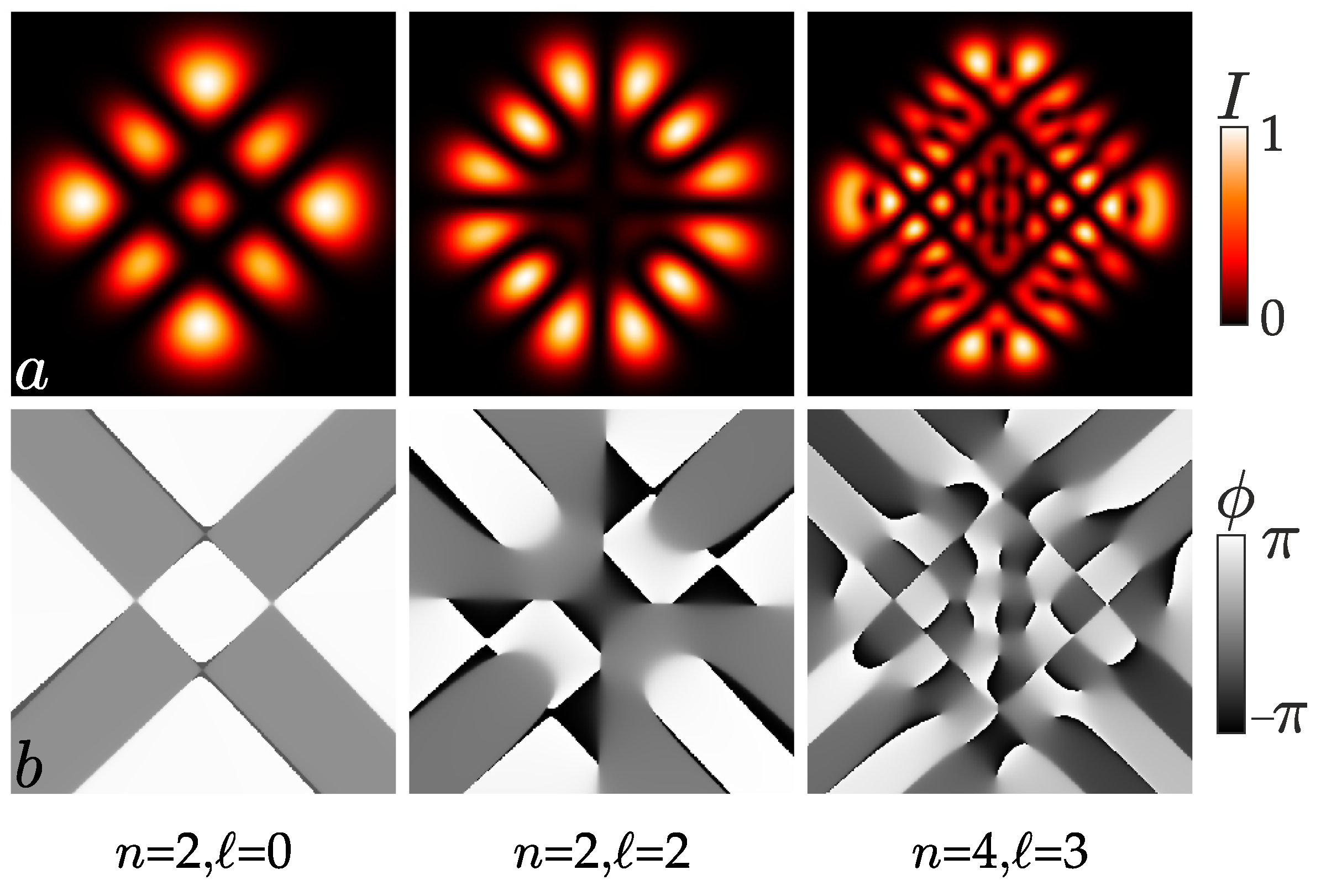
Generally speaking, the astigmatic system has a lot of control parameters, but for our experiment it is convenient to choose a = 0 , b = 1 , ϵ = 1 , leaving the quantum numbers n, , the phase parameter θ and the angle β of astigmatism. This allows us to observe structurally stable vortex beams in the plane of the double focus of a cylindrical lens experimentally. Typical intensity and phase patterns of the astigmatic structured asLG n , beam are illustrated in Figure 1 for various quantum numbers n, , the direction of the astigmatism axis β and the phase parameter θ .
Variations of the control parameters θ and β make it possible to form the most intricate phase patterns containing complex chains of topological dipoles (pairs of optical vortices with opposite signs of topological charges (TC)), but it is not possible to create a beam with a single optical vortex and different TC. It is this quality of the array of matched vortex modes that allows one to create structured beams and control their parameters in an astigmatic medium with unique OAM properties.

3. Geometry of the Astigmatic Transform of sLG Beams

The inherent symmetry of the HLG modes, whose properties are described within the framework of unitary transforms, found a natural mapping on the surface of the 2D Poincare sphere, imparting a simple and attractive geometrical interpretation the HLG modes (see, e.g., Refs. [18,19,20,21,22] and references therein). In fact, this geometric representation continues the vivid similarity between spin and orbital angular momentum. Moreover, this analogy has found its continuation in the interpretation of HG, LG and HLG modes in terms of the Hamiltonian dynamics of a 2D oscillator followed by canonical quantization, and their representation through an array of rays on a generalized Majorana sphere [23,24], which reveals the hidden symmetries of structured beams. Meanwhile, structured astigmatic LG (asLG) beams containing two HLG modes with different control parameters are already losing their former symmetry, and their geometric representation requires mapping onto a sphere of higher dimensions, and consequently the loss of geometric simplicity.
Note that the authors of the article [15] employ the unitary properties of astigmatic transforms to geometrically describe the beam evolution on a 2D sphere, characterizing the beam states by the angles α and φ ˜ . In the case of a structured asLG beam, we are already dealing with the motion of two points on a sphere, the general evolution of which is reduced to the Equations (A5) and (A7), i.e., through the angles θ ˜ and φ ˜ as functions of the phase parameter θ and the angle β of the astigmatic medium. Then the state of the asLG beam on the sphere of the unit radius can be parameterized as
X = sin 2 θ ˜ cos φ ˜ , Y = sin 2 θ ˜ sin φ ˜ , Z = cos 2 θ ˜ ,
so that X 2 + Y 2 + Z 2 = 1 .
Figure 2 highlights two families of trajectories on the hemisphere controlled by (a) the phase parameters θ at specified values β and (b) the angle β at specified phase parameters θ . The trajectories on the sphere do not reflect the evolution of the OAM, as it was discussed in earlier articles [18,19], but they highlight a featured evolution of the structured asLG beam states as a whole for different n and numbers. Four sectors are separated by the main meridians at planes (a) X 0 Z and Y 0 Z or (b) bisecting these sectors. The sectors are connected by a common point of the north pole where the trajectories are crossed, while the equator restricts them from below. Note that as the angle β tends to π / 4 , the trajectories in Figure 2a are pulled together at the north pole point. At the same time, when θ tends to zero or π , all the trajectories in Figure 2a also converge to a point at the north pole. This means that ambiguities arise near the pole, the main meridians and the equator, which require careful physical interpretation. Thus, the movement along the meridians describes chiefly the structural variations of the intensity pattern, while the movement along the equator tracks the rotation of the intensity pattern as a whole.
Near the equator (Figure 2a) at β 0 , π / 2 , π , 3 π / 2 , the trajectories are very weakly dependent on the phase parameter θ . Since the phase parameter θ controls the structure of the beam intensity pattern, it should be expected that the beam intensity pattern will vary slightly over a wide range of angles β . In addition, trajectories with opposite parameter signs are separated by the main meridians in Figure 2a,b. This means that the beam states for these parameters can change radically. Although, at first glance, it seems that the beam properties in different sectors in Figure 2a,b are periodically reproduced, as we noted above, rotational symmetry is broken in sLG beams. This will manifest itself in various properties of the beam in neighboring sectors when the astigmatic medium rotates clockwise or counterclockwise, while the common intersection point at the pole indicates the general properties of the modes at the angle π / 4 or 3 π / 4 of the astigmatism axis. We will consider these effects in the following sections. (See also Section 5.).

4. The OAM Variations

The resulting complex amplitude (6) of the asLG beam makes it possible to calculate the OAM per photon by the standard technique (see Appendix B). Substitution of the values
c 1 = e i ( β + π / 4 ) ; c 2 = ϵ ( i ) n + e i ( 2 n + ) Θ e i φ ˜ ; ( n 1 , m 1 ) = ( n + , n ) ; ( n 2 , m 2 ) = ( n , n + ) ; α 1 = π / 4 ω ; α 2 = θ ˜ ; ω = arctan   b ; γ = π / 4 γ ˜ .
into (A16) leads to the following expression:
z asLG n , ( r , ϵ , θ , b , β ) = sin 2 α 1 ϵ 2 sin 2 α 2 + 2 Re { c 1 c 2 · U } 1 + ϵ 2 + 2 Re { c 1 c 2 · V } ,
where
U = λ n ( n , n + ) ( α 1 , α 2 , γ ) sin 2 α 1 ( n + + 1 ) λ n 1 ( n , n + ) ( α 1 , α 2 , γ ) + ( n + 1 ) λ n + 1 ( n , n + ) ( α 1 , α 2 , γ ) cos 2 α 1 , V = λ n ( n , n + ) ( α 1 , α 2 , γ ) .
As expected, the rotation of the astigmatic medium brings to light some hidden properties of the sLG beam. Indeed, in an ordinary structured sLG beam there are modes with the OAM in the range ± ( 2 n + ) . However, such a wide OAM spectrum only leads to fast oscillations with variations in the phase parameter θ [13] in the sLG beam with a disturbed rotational symmetry, the amplitude of which does not exceed the azimuthal number of the beam. The situation changes dramatically if the beam propagates through a medium with simple astigmatism, where there are super bursts of the OAM [17], the amplitude of which exceeds half of the radial number n of the asLG beam provided that the azimuthal number is not zero, 0 . Otherwise ( = 0 ), the OAM disappears, and z = 0 .
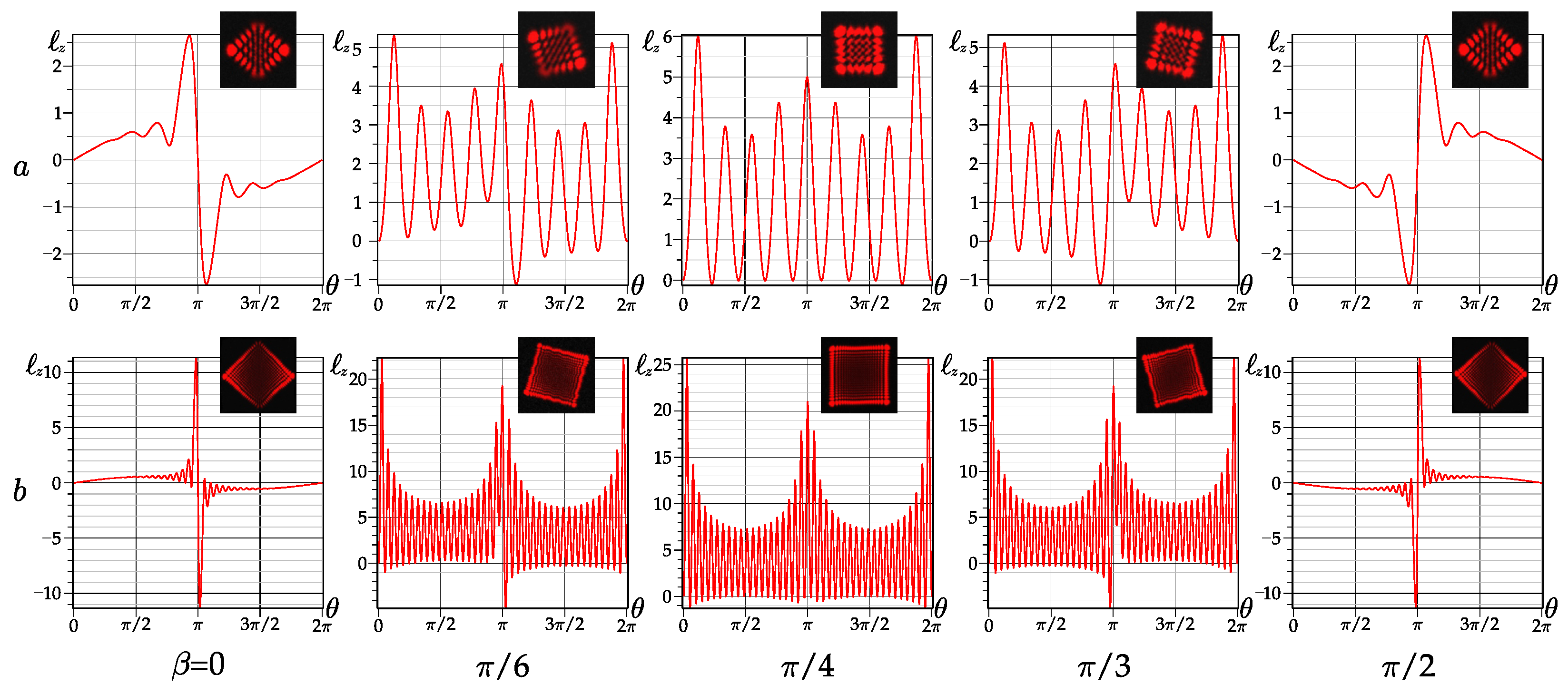
A detailed pattern of the OAM evolution is presented in Figure 3 and Figure 4. First of all, the amplitude and frequency of fast oscillations grow as increasing both the radial n and azimuthal numbers. The general astigmatism involves both azimuthal and radial n numbers in the OAM process, splitting degeneracy of ring dislocations and sorting vortices with positive and negative TC. As a result, the asLG beams with a super large OAM are formed, which exceeds the sum of the radial n and azimuthal numbers.
By examining the OAM for large values (both radial and azimuthal numbers, shown in Figure 4) we revealed that the OAM maximum can exceed the sum m a x | n + | for axis direction β = π / 4 ± π , while the OAM changes the sign when the axis of astigmatism is rotated by an angle π / 2 provided that n / 2 (see Figure 4b). If this condition is violated (i.e., > n / 2 ), then the OAM is sharply reduced to z n , as shown in Figure 4b. The maximum possible OAM is theoretically estimated as max z = | 2 n + | , which has not yet been detected. In the vortex mode spectra, satellites are always present along with the desired modes. The problem of suppressing unwanted satellites is awaiting its solution.
The physical mechanism responsible for the involvement of the radial number n in the OAM lies beyond the scope of this article, but we can say with confidence that it is associated with the transformation of ring dislocations into a vortex array due to the astigmatism. It is convenient to calculate the contribution of vortex and astigmatic processes to the OAM by means of the intensity moments technique [25]. For example, the maximum contribution to OAM is made by the asLG beam with a quadrangular intensity pattern in Figure 4. Nevertheless, the quadrangular shape of the intensity pattern in Figure 4 is similar to the vortex-free HG mode with a featured intensity distribution.When propagating the beam, the tetragon rotates, following the generatrix rays.

5. The Beam Structure Following the Rotation of the Cylindrical Lens

As we noted above, a structured LG beam in a medium with a simple astigmatism has invariance points that connect the parameters of the beam and the medium when the beam propagates through the medium without changing its structure. However, our preliminary theoretical and experimental studies have shown that we have not yet found such conditions in the case of a general astigmatism. Nevertheless, as we will show later, the property of beam invariance with a simple astigmatism acquires new features, with general astigmatism, manifested in the preservation of structural stability when changing the medium parameters. The background for such properties of the astigmatic medium are reflected in the form of trajectories on the sphere in Figure 2. In Section 3 and in Figure 2b, we revealed that the trajectories of the asLG beam states on the sphere are divided by the main meridians into four sectors corresponding to the different response of the structured asLG beam to the direction of axis rotation of the astigmatic system. In addition, trajectories with phase parameters θ ˜ near to the values of θ = π / 4 , 3 π / 4 , 5 π / 4 almost do not change the magnitude of the control parameter θ ˜ responsible for the structural transformations of the beam. We found, experimentally, that at certain values of the phase parameter θ , the rotation of the cylindrical lens synchronously rotates the intensity pattern. In some range of the phase parameter near θ = π , the pattern structure does not change, but synchronously rotates φ ˜ β . However, there were deviations from this pattern. Namely, note the difference in the intensity pattern variations when the cylindrical lens axis rotates clockwise and counterclockwise. These observations forced us to take a close theoretical and experimental look at these processes.
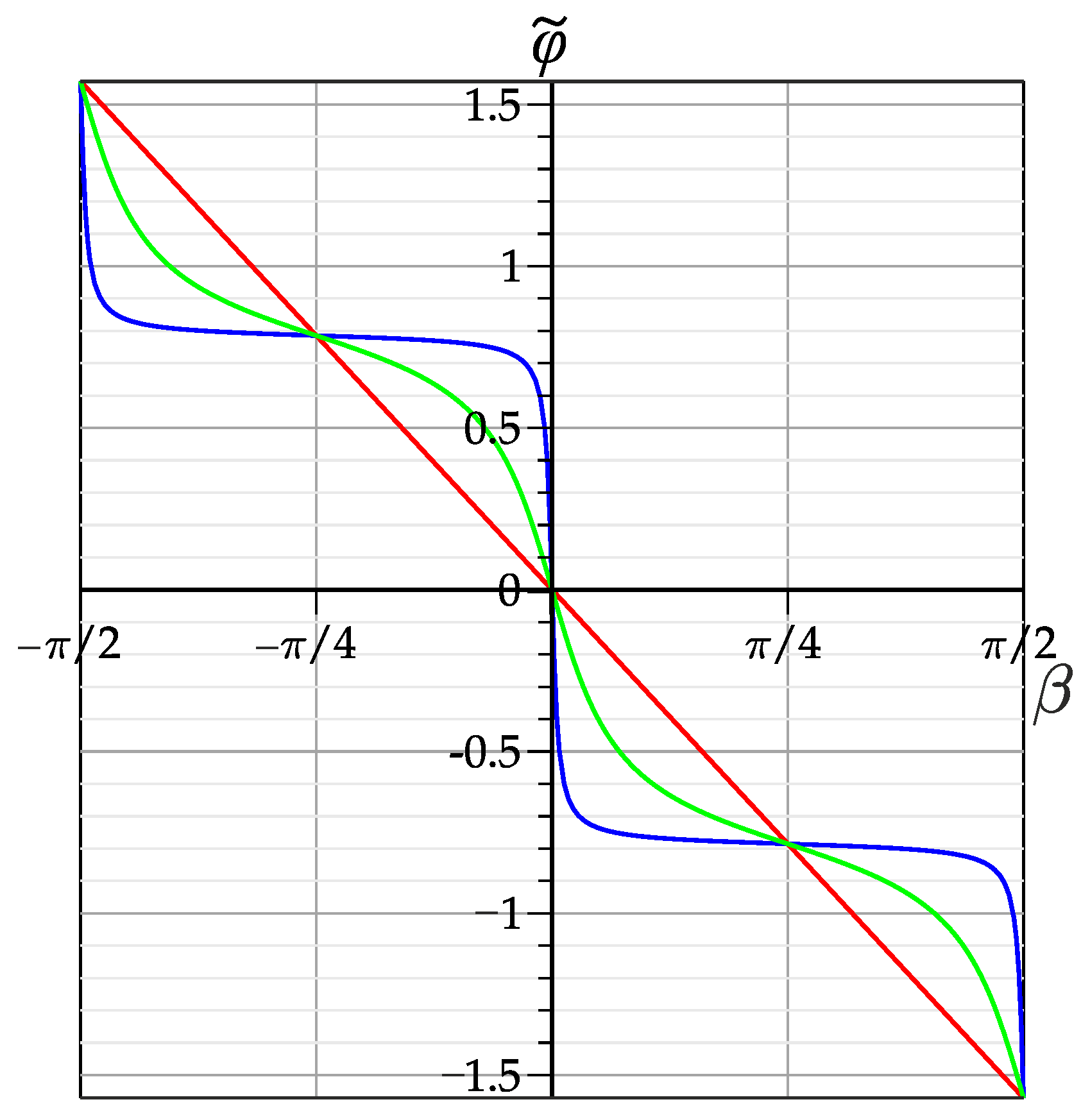
The intensity pattern rotation as a whole (movement along the equator in Figure 2) is tracked by the angle φ ˜ in Equation (A7). From Equation (7), we find
φ ˜ = arctan ( Y / X )
The curves in Figure 5 represent the dependence φ ˜ ( β , θ ) of the rotation angle φ ˜ of the intensity pattern as a whole on the rotation angle β of the cylindrical lens for various phase parameters θ . We see in Figure 5 that for the phase parameter θ = 0.51 π , the blue curve has an almost Π -like shape. As the phase parameter approaches θ = π , the curves take the form of an inclined sinusoid, so that in the vicinity of θ = π , a directly proportional φ ˜ = β dependence is observed. However, the presented dependences observed in the experiment in the Figure 6 are not reflected in the form of curves in Figure 5, where the difference of the beam structure is not reflected when the lens rotates clockwise and counterclockwise, which requires detailed experimental observations.
Our experiment used an experimental setup described in detail in our recent article [16] on a simple astigmatism. A sketch of the experimental setup is shown in Figure 8 in Ref. [16] with a cylindrical lens with focal length f c l = 15 cm being the only difference. The cylindrical lens is mounted on a turntable, which allowed controlling the rotation angle β of its axis up to a quarter of the angular degree. The beam was formed on an spatial light modulator (SLM) device with a specified radial n and azimuthal numbers, amplitude ϵ and phase θ parameters, whereas the astigmatism angle β was set by the direction of the cylindrical lens axis. The intensity pattern was recorded and digitally processed at the plane of the double focus z = 2 f c l of the cylindrical lens.
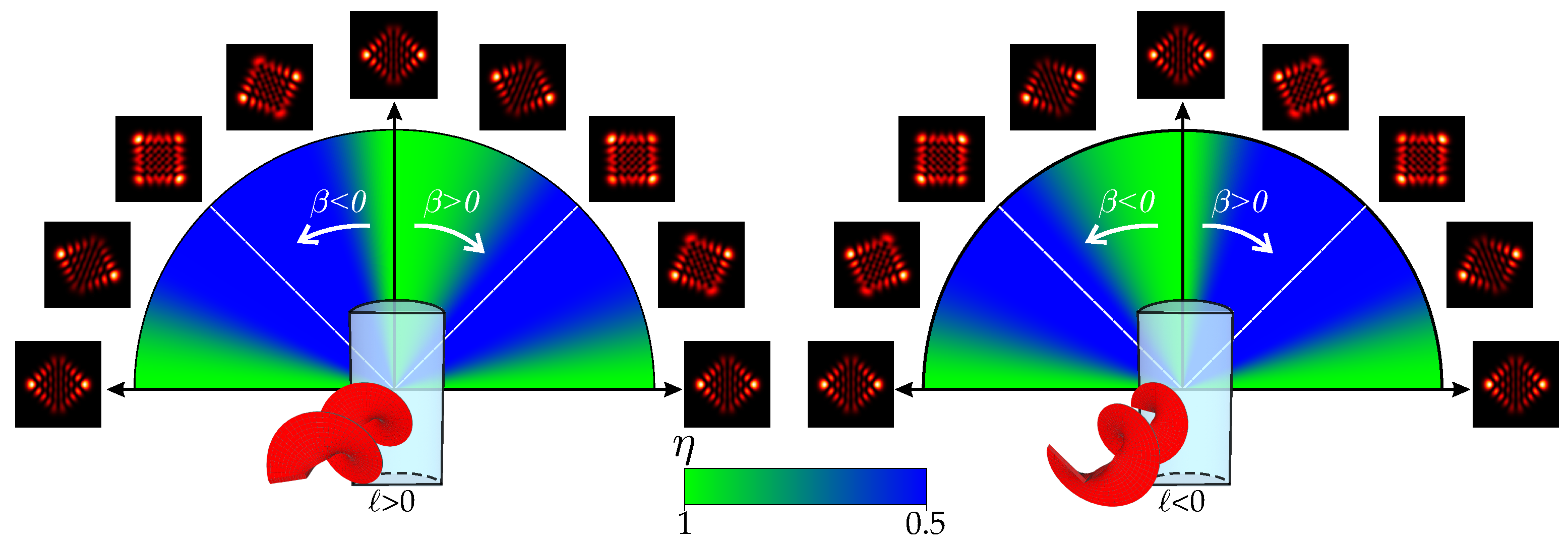
The sketch in Figure 7a illustrates the variations of the intensity pattern as the angle β changes. We revealed experimentally that the intensity pattern structure of the asLG beam with a positive TC ( > 0 ) depends on the rotation direction of the angle β , and when the cylindrical lens rotates clockwise, the beam structure remains unchanged, in a wide range of the β angles, rotating synchronously with the rotation of the cylindrical lens (i.e., the beam structure follows the rotation of the cylindrical lens), while the rotation going anticlockwise causes a fast breakdown of the HLG beam asLG beam structure. To find out the reasons for asymmetric destroying the original beam structure when the cylindrical lens is rotated, we changed the TC sign ( < 0 ) of the initial sLG beam. It turned out the ranges of structural stability and instability to be reversed. Now the beam structure for the cylindrical lens rotation is manifested itself at the negative angles ( β < 0 ).
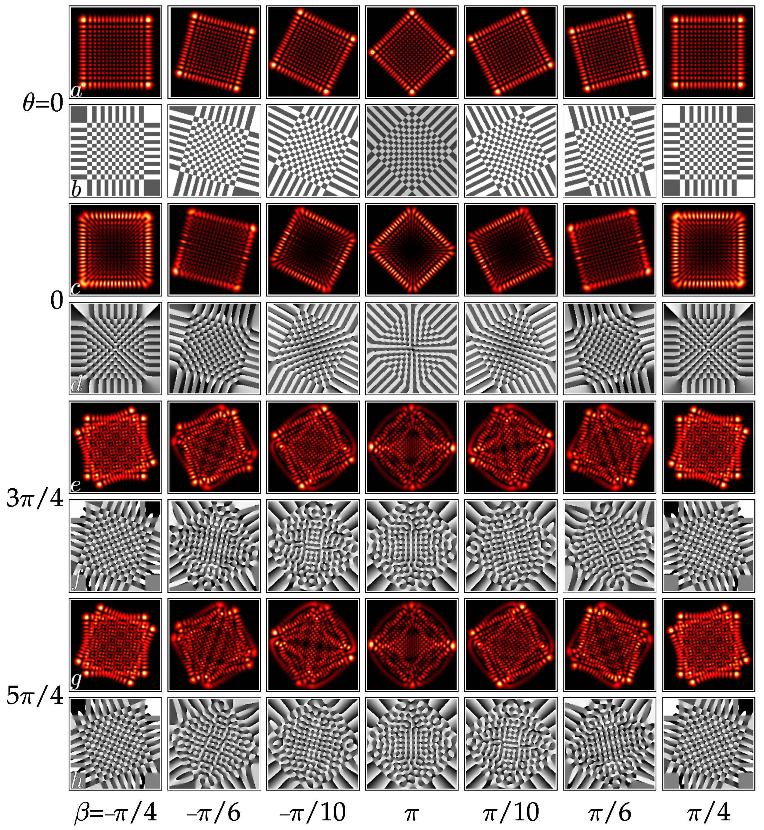
However, as can be seen from Figure 3 for β = 0 , the OAM changes sign at the phase parameter θ = π . Therefore, we were interested in how the beam structure will change at the intersection of the critical point θ = π . The answer to this question is given in Figure 7. The first line in Figure 7 (our computer simulation) tracks variations of the asLG beam-intensity pattern with zero TC ( = 0 ) when the cylindrical lens axis rotates at the angle β both clockwise and counterclockwise. We see that at the critical point β = π , the beam with zero TC does not distinguish the direction of rotation, so that the rotation of the intensity pattern follows the rotation of the cylindrical lens without changing its fine intensity structure. The beam with a nonzero ( = 1 ) TC behaves somewhat differently (see the second line of Figure 7). There is a weak rearrangement of intensity at the rectangle vertices and along its diagonal when rotating counterclockwise and clockwise, which indicates a change in the OAM z sign. Nevertheless, the directions of the rectangle diagonals follow the direction of the lens axis (see also Figure 5, red curve). The situation radically changes with sufficiently large phase θ = 3 π / 4 parameters (see the third line in Figure 7) in the range of the positive OAM. The rotation of the lens leads to a fast realignment of the fine intensity structure, the intensity pattern dramatically depends on the direction of lens rotation. The transition to the region of negative OAM for the phase parameter θ = 5 π / 4 again leads to a realignment of the intensity pattern when rotating clockwise and counterclockwise (see the fourth line in Figure 7). Although in both cases the effect of following the intensity pattern the cylindrical lens rotation is violated, there is a strong correlation between the fine intensity structure and the lens rotation. Indeed, a comparison of the intensity patterns in the third and fourth lines of Figure 7 shows that their fine structure coincides if the direction of the cylindrical lens rotation is changed simultaneously with the change of the OAM sign, i.e., the product of the OAM on the rotation sign of the lens should remain unchanged z · sgn ( β ) = const .
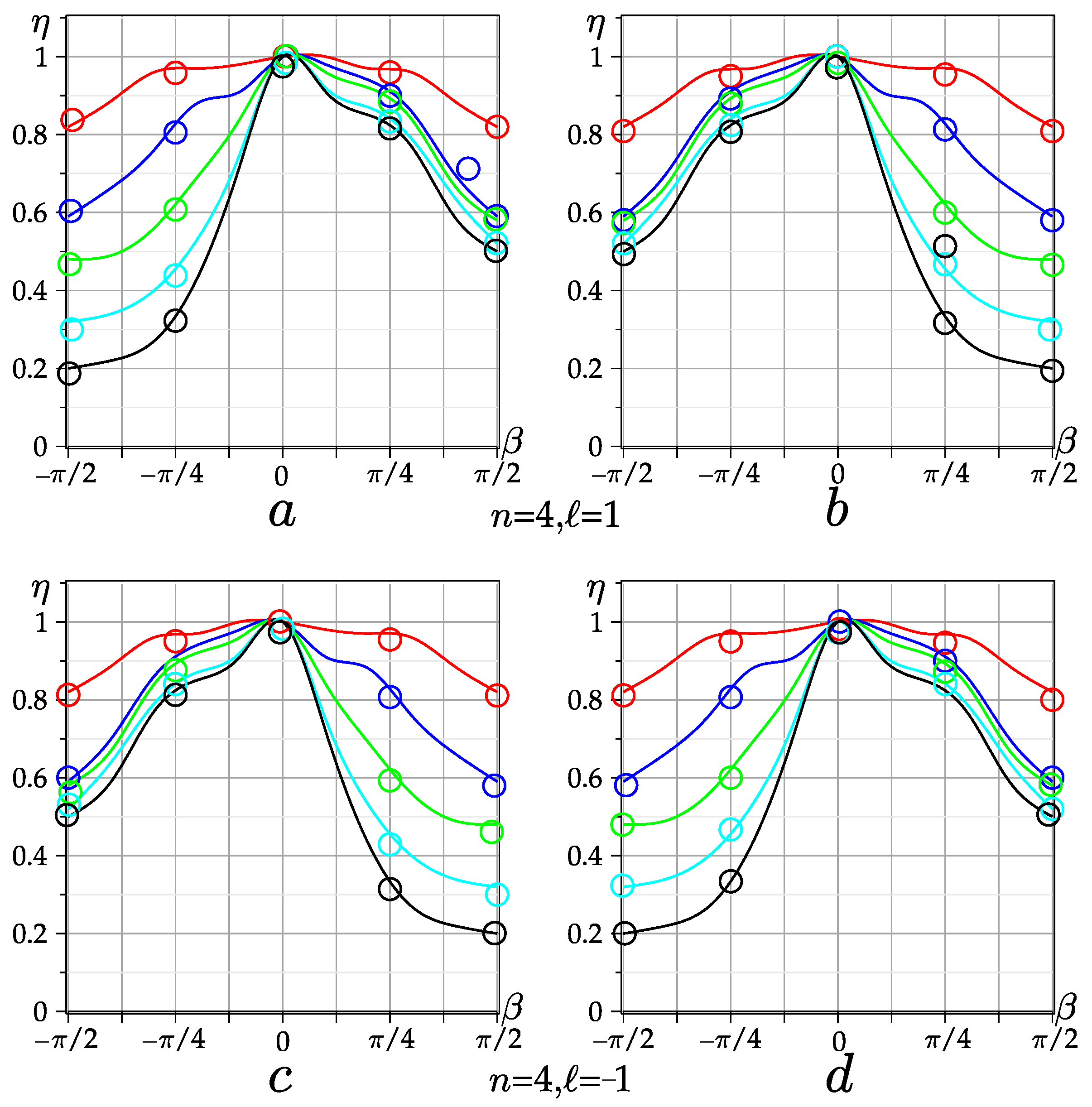
In order to confirm experimentally the obtained theoretical results on the beam structure following the cylindrical lens rotation, we determined the correlation degree η of the initial intensity patterns at β = 0 with those at different angles of cylindrical lens rotation β , taking into account the phase parameter θ and the OAM z . The experimentally measured correlation degrees η ( β ) of the intensity patterns with a simple astigmatism and a general astigmatism with the rotation angle β and the OAM z are shown in Figure 8. The red curve in Figure 8, describing the correlation degree η ( β ) of the asLG beam with zero OAM z = 0 , is symmetrical with respect to the rotation angle β , which corresponds, taking into account the 5 % measurement error, to the results of the computer simulation in Figure 7 (first line). As soon as the OAM of the asLG beam is not zero, the symmetry of the correlation curves disappear, and the difference in the behavior of the curve branches η ( β ) depends both on the direction of rotation β and the beam’s OAM with a simple astigmatism β = 0 (see Figure 4) and on the initial OAM (the azimuthal number > 0 or < 0 of the sLG beam) with general astigmatism. All families of curves in Figure 8 differ by the sign of the lens rotation clockwise and counterclockwise, but coincide with each other (within the measurement error) provided that the product of the OAM and the sign of the angle of rotation are the same z · sgn ( β ) = const . It is important to note that in the range of angles β ( 0 , ± π / 8 ) , the effect of the beam structure following the rotation of the cylindrical lens rotation is fulfilled, and disappears when this condition is violated.
It is worth noting that the anticipation of the effect of the beam structure following the cylindrical lens rotation is based on two independent effects. The first concerns the effect of the polarization following the birefringence axis of the anisotropic plates stack [26] or in a chiral photonic crystal [27]. The second one touches upon the conversion of a singular beam TC in a system of two cylindrical lenses [28]. However, the above effect is observed only a narrow angle range near the OAM minima of structured LG beams (see Figure 7b).We expect this effect to be observed for all structured beams in a stack of cylindrical lenses whose axes are slightly rotated relative to each other.
6. Conclusions

The properties of structured sLG beams in an astigmatic medium is an important example revealing the hidden properties of standard LG and HLG beams in violation of rotational symmetry. The rotation of these beams clockwise and counterclockwise does not change their properties. Once these beams are added together, the property of rotational symmetry is broken, but instead the fast OAM oscillations appear, the frequency of which is specified by the radial number of the sLG beam.However, their amplitude does not exceed the initial beam topological charge (equal to the azimuthal number of the initial LG mode). Nevertheless, its spectrum becomes wide, containing the OAM equal to twice the radial number plus an azimuthal number with opposite signs OAM = ± ( 2 n + ) .
We have shown that in a medium with general astigmatism, the situation changes dramatically. Two main features can be emphasized. The first of them is that the OAM extremes occur at the angle β = π / 4 of the astigmatism at any values of the phase parameter θ , but their maximum value (more than n + ) is possible only for optimal values of the phase parameter. The second main property the effect of the beam structure following the angle of the cylindrical lens rotation is manifested providing that the product of the OAM and rotation angle is constant. It is worth noting that we have covered only part of the hidden properties of structured beams that have lost rotational symmetry. Further detailed theoretical and experimental search must explore the conditions under which maxima OAM 2 n + are found by suppressing unwanted mode satellites. In addition, detailed research requires looking for conditions under which the effect of the beam structure following the cylindrical lens rotation is performed in a wide range of angles. Finally, the theory of transforms of the OAM, due to the breakdown of ring dislocations in an astigmatic medium, is awaiting development.

Author Contributions

Conceptualization, A.V. and A.V.; software, M.B.; validation, E.A., A.V. and S.K.; formal analysis, M.B.; investigation, A.V., Y.A. and S.K.; writing—original draft preparation, A.V. and E.A.; writing—review and editing, A.V.; visualization, M.B. and Y.A. All authors have read and agreed to the published version of the manuscript.

Funding

This work was supported by the Russian Science Foundation (grant 23-22-00314).

Institutional Review Board Statement

Not applicable.

Informed Consent Statement

Not applicable.

Data Availability Statement

The data presented in this study are available on request from the corresponding author.

Conflicts of Interest

The authors declare no conflict of interest.

Appendix A. Astigmatic Transform of sLG Beams

Here we obtain the expression of the general astigmatic transform (GAT) of the structures LG beam, Equation (2). We start with the GAT of a HLG mode, considered in Ref. [12]:
F exp i a | ρ | 2 + i b ψ ( ρ , β ) HLG n , m ( ρ | α ) ( r ) = = 1 2 π R 2 exp i r , ρ + i a ρ 2 + i b ψ ( ρ , β ) HLG n , m ( ρ | α ) d 2 ρ = = ( i ) n + m 2 | σ + σ | exp i Ψ ( r , β ) 4 | σ + σ | 2 + i ( n m ) φ ˜ + i ( n + m + 1 ) ω + HLG n , m R γ ˜ S R β r | θ ˜ ,
where σ ± = 1 + i ( a ± b ) , Ψ ( r , β ) = a ( 1 + a 2 b 2 ) r 2 + b ( 1 + b 2 a 2 ) ψ ( r , β ) , the astigmatic influence function ψ ( r , β ) is defined in Equation (1), ω ± = 1 2 ( arg σ + ± arg σ ) , R α is a rotation matrix at the angle α , and S = 1 2 1 / | σ + | 0 0 1 / | σ | is a diagonal matrix. The parameters θ ˜ ,   γ ˜ ,   φ ˜ are solutions of the following system of equations:
sin 2 θ ˜ = sin 2 α cos 2 ω + cos 2 α sin 2 β sin 2 ω ,
e 2 i γ ˜ cos 2 θ ˜ = cos 2 α cos 2 β + i ( sin 2 α sin 2 ω cos 2 α sin 2 β cos 2 ω ) ,
e i φ ˜ ± i θ ˜ = e i ω ( cos γ ˜ sin γ ˜ ) ( cos α cos β + i sin α sin β ) e i ω ( sin γ ˜ ± cos γ ˜ ) ( cos α sin β i sin α cos β ) .
In all the equations, lhs contains the parameters of the output field only, ( θ ˜ , γ ˜ , φ ˜ ) , while rhs contains the parameters of the input field, ( a , b , α , β ) . We need to find only one solution of the system (A2)–(A4) since any other leads to the same rhs of (A1). In fact, first two equations are used for deriving the values of θ ˜ and γ ˜ , while the third one provides the value of φ ˜ . Moreover, in Equation (A4) there are two equations depending on the sign selection, and the value of φ ˜ is derivable from any of them.
Solving the system (A2)–(A4) we first find | cos 2 θ ˜ | , then θ ˜ and γ ˜ , and finally φ ˜ from any of two variants of Equation (A4):
θ ˜ = 1 2 arg { δ · ( cos 2 α cos 2 β ) 2 + ( sin 2 α sin 2 ω cos 2 α sin 2 β cos 2 ω ) 2 + + i ( sin 2 α cos 2 ω + cos 2 α sin 2 β sin 2 ω ) } ,
γ ˜ = 1 2 arg δ · cos 2 α cos 2 β + i ( sin 2 α sin 2 ω cos 2 α sin 2 β cos 2 ω ) ,
φ ˜ = θ ˜ + arg { e i ω ( cos γ ˜ sin γ ˜ ) ( cos α cos β + i sin α sin β ) e i ω ( sin γ ˜ + cos γ ˜ ) ( cos α sin β i sin α cos β ) } , φ ˜ = θ ˜ + arg { e i ω ( cos γ ˜ + sin γ ˜ ) ( cos α cos β + i sin α sin β ) e i ω ( sin γ ˜ cos γ ˜ ) ( cos α sin β i sin α cos β ) } .
Here δ = ± 1 is a new parameter. It may be chosen as δ = 1 everywhere, however, sometimes the selection δ = 1 leads to simpler expressions. In particular, if a = α = 0 , then ω = arctan   b . Selecting δ = sgn ( cos 2 β ) , we have ( θ ˜ , γ ˜ , φ ˜ ) = ( β , 0 , π / 4 ) . If needed, the arguments of all three output parameters will be pointed out, for example, θ ˜ = θ ˜ ( α , β , ω , δ ) .
Now we apply these results to the GAT of sLG beams when the defocusing parameter is missing, a = 0 . Then σ ± = 1 ± i b , ω + = 0 , ω = arctan   b , Ψ ( r , β ) = b ( 1 + b 2 ) ψ ( r , β ) , S is reduced to the unit matrix, S = I / 2 1 + b 2 , and
F exp i b ψ ( ρ , β ) sLG n , ( ρ | ϵ , θ ) ( r ) = = ( 1 ) n 2 n + n ! · ( i ) 2 n + 2 1 + b 2 exp i b ψ ( r , β ) 4 ( 1 + b 2 ) · asLG n , ( r | ϵ , θ , b , β ) ,
asLG n , ( r | ϵ , θ , b , β ) = e i ( β + π / 4 ) HLG n + , n ( R π / 4 β r 2 1 + b 2 π 4 ω + + ϵ ( i ) n + e i ( 2 n + ) Θ e i φ ˜ HLG n , n + ( R γ ˜ β r 2 1 + b 2 θ ˜ ,
where the parameters of the second HLG component are defined by Equations (A5)–(A7), θ ˜ = θ ˜ ( Θ , β π / 4 , ω , δ ) , γ ˜ = γ ˜ ( Θ , β π / 4 , ω , δ ) , φ ˜ = φ ˜ ( Θ , β π / 4 , ω , δ ) .

Appendix B. Expansion of an asLG Beam into the Series of LG Modes

Let us consider a superposition of two rotated HLG beams with different parameters,
F ( r ) = c 1 HLG n 1 , m 1 ( R γ 1 r | α 1 ) + c 2 HLG n 2 , m 2 ( R γ 2 r | α 2 ) ,
and evaluate the orbital angular momentum: z [ F ] = L / E , where
E = F 2 = R 2 | F ( r ) | 2 d 2 r , L = R 2 Im { F ( r ) ϕ F ( r ) } d 2 r .
Since the OAM of a light field has no dependence on the rotation of its argument, we change the variables, r R γ 1 r with the aim to reduce a number of used parameters:
F ( r ) c 1 HLG n 1 , m 1 ( r | α 1 ) + c 2 HLG n 2 , m 2 ( R γ 2 γ 1 r | α 2 ) = c 1 HLG n 1 , m 1 ( r | α 1 ) + c 2 HLG n 2 , m 2 ( R γ r | α 2 ) ,
where γ = γ 2 γ 1 .
First we evaluate E:
E = R 2 c 1 HLG n 1 , m 1 ( r | α 1 ) + c 2 HLG n 2 , m 2 ( R γ r | α 2 ) 2 d 2 r = E 1 + E 2 + E 3 , E 1 =   | c 1 | 2 HLG n 1 , m 1 ( r | α 1 ) 2 = | c 1 | 2 · π 2 2 n 1 + m 1 n 1 ! m 1 ! , E 2 =   | c 2 | 2 HLG n 2 , m 2 ( r | α 2 ) 2 = | c 2 | 2 · π 2 2 n 2 + m 2 n 2 ! m 2 ! , E 3 =   2 Re c 1 c 2 R 2 HLG n 1 , m 1 ( r | α 1 ) HLG n 2 , m 2 ( R γ r | α 2 ) d 2 r .
If n 1 + m 1 n 2 + m 2 , then E 3 = 0 . If n 1 + m 1 = n 2 + m 2 = N , then n 1 = N m 1 , n 2 = N m 2 , and the expansion of an HLG beam in HLG beams with different parameter is as follows:
HLG n , m ( R γ r | θ ) = k = 0 n + m λ k ( n , m ) ( α , θ , γ ) HLG n + m k , k ( r | α ) ,
λ k ( n , m ) ( α , θ , γ ) = ( 1 ) k { cos γ cos ( θ α ) + i sin γ sin ( θ + α ) } n k × ×   { cos γ sin ( θ α ) i sin γ cos ( θ + α ) } m k × ×   P k ( n k , m k ) sin 2 γ cos 2 ( θ + α ) cos 2 γ cos 2 ( θ α ) .
Then
HLG N m 2 , m 2 ( R γ r | α 2 ) = k = 0 N λ k ( N m 2 , m 2 ) ( α 1 , α 2 , γ ) HLG N k , k ( r | α 1 ) = = λ m 1 ( N m 2 , m 2 ) ( α 1 , α 2 , γ ) HLG N m 1 , m 1 ( r | α 1 ) +
(only the term k = m 1 gives a nonzero contribution into E 3 ) and
E 3 = 2 Re { c 1 c 2 λ m 1 ( N m 2 , m 2 ) ( α 1 , α 2 , γ ) } · π 2 2 N ( N m 1 ) ! m 1 ! .
Now we evaluate L:
L = R 2 Im { F ( r ) ϕ F ( r ) } d 2 r = L 1 + L 2 + L 3 , L 1 = | c 1 | 2 R 2 Im { HLG n 1 , m 1 ( r | α 1 ) ϕ HLG n 1 , m 1 ( r | α 1 ) } d 2 r = = | c 1 | 2 · z HLG n 1 , m 1 ( r | α 1 ) · HLG n 1 , m 1 ( r | α 1 ) 2 = = | c 1 | 2 · ( n 1 m 1 ) sin 2 α 1 · π 2 2 n 1 + m 1 n 1 ! m 1 ! , L 2 = | c 2 | 2 R 2 Im { HLG n 2 , m 2 ( r | α 2 ) ϕ HLG n 2 , m 2 ( r | α 2 ) } d 2 r = = | c 2 | 2 · z HLG n 2 , m 2 ( r | α 2 ) · HLG n 2 , m 2 ( r | α 2 ) 2 = = | c 2 | 2 · ( n 2 m 2 ) sin 2 α 2 · π 2 2 n 2 + m 2 n 2 ! m 2 ! , L 3 = Im c 1 c 2 R 2 HLG n 1 , m 1 ( r | α 1 ) ϕ HLG n 2 , m 2 ( R γ r | α 2 ) d 2 r + + Im c 1 c 2 R 2 HLG n 2 , m 2 ( R γ r | α 2 ) ϕ HLG n 1 , m 1 ( r | α 1 ) d 2 r = = 2 Im c 1 c 2 R 2 HLG n 2 , m 2 ( R γ r | α 2 ) ϕ HLG n 1 , m 1 ( r | α 1 ) d 2 r .
Since
ϕ HLG n , m ( r | α ) = { x y y x } HLG n , m ( r | α ) = i { m cos 2 α HLG n + 1 , m 1 ( r | α ) n cos 2 α HLG n 1 , m + 1 ( r | α ) + ( n m ) sin 2 α HLG n , m ( r | α ) } .
The imaginary unit factor in rhs demonstrates that L 3 can be reduced to the sum of three integrals of the kind of E 3 , where the index pair ( n 2 , m 2 ) keeps unchanged while the index pair ( n 1 , m 1 ) takes the values ( n 1 + 1 , m 1 1 ) , ( n 1 1 , m 1 + 1 ) and ( n 1 , m 1 ) . As a corollary, if n 1 + m 1 n 2 + m 2 , then L 3 = 0 . If n 1 + m 1 = n 2 + m 2 = N , then
L 3 = { m 1 cos 2 α 1 · E 3 | m 1 m 1 1 n 1 cos 2 α 1 · E 3 m 1 m 1 + 1 + ( n 1 m 1 ) sin 2 α 1 · E 3 = = π 2 2 N · 2 Re { c 1 c 2 ( m 1 cos 2 α 1 · ( N m 1 + 1 ) ! ( m 1 1 ) ! · λ m 1 1 ( N m 2 , m 2 ) ( α 1 , α 2 , γ ) ( N m 1 ) cos 2 α 1 · ( N m 1 1 ) ! ( m 1 + 1 ) ! · λ m 1 + 1 ( N m 2 , m 2 ) ( α 1 , α 2 , γ ) + + ( N 2 m 1 ) sin 2 α 1 · ( N m 1 ) ! m 1 ! · λ m 1 ( N m 2 , m 2 ) ( α 1 , α 2 , γ ) ) } = = π 2 2 N ( N m 1 ) ! m 1 ! · 2 Re { c 1 c 2 ( ( N m 1 + 1 ) cos 2 α 1 · λ m 1 1 ( N m 2 , m 2 ) ( α 1 , α 2 , γ ) ( m 1 + 1 ) cos 2 α 1 · λ m 1 + 1 ( N m 2 , m 2 ) ( α 1 , α 2 , γ ) + ( N 2 m 1 ) sin 2 α 1 · λ m 1 ( N m 2 , m 2 ) ( α 1 , α 2 , γ ) ) } .
As result, if n 1 + m 1 n 2 + m 2 , then
z [ F ] = | c 1 | 2 · 2 n 1 + m 1 n 1 ! m 1 ! · ( n 1 m 1 ) sin 2 α 1 + | c 2 | 2 · 2 n 2 + m 2 n 2 ! m 2 ! · ( n 2 m 2 ) sin 2 α 2 | c 1 | 2 · 2 n 1 + m 1 n 1 ! m 1 ! + | c 2 | 2 · 2 n 2 + m 2 n 2 ! m 2 ! .
If n 1 + m 1 = n 2 + m 2 = N , then the OAM may be written as follows:
z [ F ] = | c 1 | 2 · ( N 2 m 1 ) sin 2 α 1 + | c 2 | 2 · ( N m 2 ) ! m 2 ! ( N m 1 ) ! m 1 ! ( N 2 m 2 ) sin 2 α 2 + 2 Re { c 1 c 2 · U } | c 1 | 2 + | c 2 | 2 · ( N m 2 ) ! m 2 ! ( N m 1 ) ! m 1 ! + 2 Re { c 1 c 2 · V } ,
where
U = ( N 2 m 1 ) λ m 1 ( N m 2 , m 2 ) ( α 1 , α 2 , γ ) sin 2 α 1 ( N m 1 + 1 ) λ m 1 1 ( N m 2 , m 2 ) ( α 1 , α 2 , γ ) + ( m 1 + 1 ) λ m 1 + 1 ( N m 2 , m 2 ) ( α 1 , α 2 , γ ) cos 2 α 1 , V = λ m 1 ( N m 2 , m 2 ) ( α 1 , α 2 , γ ) .

References

  1. Willner, A.E.; Song, H.; Zou, K.; Zhou, H.; Su, X. Orbital angular momentum beams for high-capacity communications. J. Light. Technol. 2023, 41, 1918–1933. [Google Scholar] [CrossRef]
  2. Shen, Y.; Wang, X.; Xie, Z.; Min, C.; Fu, X.; Liu, Q.; Gong, M.; Yuan, X. Optical vortices 30 years on: OAM manipulation from topological charge to multiple singularities. Light Sci. Appl. 2019, 8, 90. [Google Scholar] [CrossRef] [Green Version]
  3. Forbes, A.; de Oliveira, M.; Dennis, M. Structured light. Nat. Photonics 2021, 15, 253–262. [Google Scholar] [CrossRef]
  4. Izdebskaya, Y.; Shvedov, V.; Volyar, A. Symmetric array of off-axis singular beams: Spiral beams and their critical points. J. Opt. Soc. Am. A 2008, 25, 171–181. [Google Scholar] [CrossRef] [Green Version]
  5. He, C.; Shen, Y.; Forbes, A. Towards higher-dimensional structured light. Light Sci. Appl. 2022, 11, 205. [Google Scholar] [CrossRef]
  6. Shen, Y.; Meng, Y.; Fu, X.; Gong, M. Hybrid topological evolution of multi-singularity vortex beams: Generalized nature for helical-Ince–Gaussian and Hermite–Laguerre–Gaussian modes. J. Opt. Soc. Am. A 2019, 36, 578–587. [Google Scholar] [CrossRef]
  7. Lukin, V.P. Outer scale of turbulence and its influence on fluctuations of optical waves. Phys. Usp. 2021, 191, 292–317. [Google Scholar] [CrossRef]
  8. Aksenov, V.P.; Dudorov, V.V.; Kolosov, V.V.; Levitsky, M.E. Synthesized vortex beams in the turbulent atmosphere. Front. Phys. 2020, 8, 143. [Google Scholar] [CrossRef]
  9. Cox, M.A.; Mphuthi, N.; Nape, I.; Mashaba, N.; Cheng, L.; Forbes, A. Structured light in turbulence. IEEE J. Sel. Top. Quant. Electr. 2021, 27, 7500521. [Google Scholar] [CrossRef]
  10. Klug, A.; Peters, C.; Forbes, A. Robust structured light in atmospheric turbulence. Adv. Photonics 2023, 5, 016006. [Google Scholar] [CrossRef]
  11. Lyubopytov, V.S.; Tlyavlin, A.Z.; Sultanov, A.K.; Bagmanov, V.K.; Khonina, S.N.; Karpeev, S.V.; Kazanskiy, N.L. Mathematical model of completely optical system for detection of mode propagation parameters in an optical fiber with few-mode operation for adaptive compensation of mode coupling. Comput. Opt. 2013, 37, 352–359. [Google Scholar] [CrossRef]
  12. Abramochkin, E.; Razueva, E.; Volostnikov, V. General astigmatic transform of Hermite-Laguerre-Gaussian beams. J. Opt. Soc. Am. A 2010, 27, 2506–2513. [Google Scholar] [CrossRef]
  13. Volyar, A.; Abramochkin, E.; Akimova, Y.; Bretsko, M.; Egorov, Y. Fast oscillations of orbital angular momentum and Shannon entropy caused by radial numbers of structured vortex beams. Appl. Opt. 2022, 23, 6398–6407. [Google Scholar] [CrossRef]
  14. Abramochkin, E.; Volostnikov, V. Beam transformations and nontransformed beams. Opt. Commun. 1991, 83, 123–135. [Google Scholar] [CrossRef]
  15. Abramochkin, E.G.; Volostnikov, V.G. Generalized Gaussian beams. J. Opt. A Pure Appl. Opt. 2004, 6, S157–S161. [Google Scholar] [CrossRef]
  16. Volyar, A.; Abramochkin, E.; Akimova, Y.; Bretsko, M. Astigmatic-invariant structured singular beams. Photonics 2022, 9, 842. [Google Scholar] [CrossRef]
  17. Volyar, A.; Abramochkin, E.; Akimova, Y.; Bretsko, M. Super bursts of the orbital angular momentum in astigmatic-invariant structured LG beams. Opt. Lett. 2022, 47, 5537–5540. [Google Scholar] [CrossRef]
  18. Dennis, M.R.; Alonso, M.A. Swings and roundabouts: Optical Poincaré spheres for polarization and Gaussian beams. Phil. Trans. R. Soc. A 2017, 375, 20150441. [Google Scholar] [CrossRef] [Green Version]
  19. Shen, Y.; Wang, Z.; Fu, X.; Naidoo, D.; Forbes, A. SU(2) Poincaré sphere: A generalized representation for multidimensional structured light. Phys. Rev. A 2020, 102, 031501(R). [Google Scholar] [CrossRef]
  20. Hsieh, C.-L.; Wang, C.-H.; Chung, W.-C.; Liang, H.-C.; Chen, Y.-F. Transition from eigenmodes to geometric modes characterized by the quantum SU(2) coupled oscillator model: A review. Opt. Continuum 2023, 2, 738–750. [Google Scholar] [CrossRef]
  21. Shen, Y. Rays, waves, SU(2) symmetry and geometry: Toolkits for structured light. J. Opt. 2021, 23, 124004. [Google Scholar] [CrossRef]
  22. Shen, Y.; Yang, X.; Naidoo, D.; Fu, X.; Forbes, A. Structured ray-wave vector vortex beams in multiple degrees of freedom from a laser. Optica 2020, 7, 820–831. [Google Scholar] [CrossRef]
  23. Dennis, M.R.; Alonso, M.A. Gaussian mode families from systems of rays. J. Phys. Photonics 2019, 1, 02500. [Google Scholar] [CrossRef]
  24. Gutierrez-Cuevas, R.; Wadood, S.A.; Vamivakas, A.N.; Alonso, M.A. Modal Majorana sphere and hidden symmetries of structured-Gaussian beams. Phys. Rev. Lett. 2019, 125, 123903. [Google Scholar] [CrossRef]
  25. Fadeyeva, T.A.; Rubass, A.F.; Aleksandrov, R.V.; Volyar, A.V. Does the optical angular momentum change smoothly in fractional-charged vortex beams? J. Opt. Soc. Am. B 2014, 31, 798–805. [Google Scholar] [CrossRef]
  26. Yariv, A.; Yeh, P. Optical Waves in Crystals; Wiley: New York, NY, USA, 1984. [Google Scholar]
  27. Alexeyev, C.N.; Egorov, Y.A.; Volyar, A.V. Mutual transformations of fractional-order and integer-order optical vortices. Phys. Rev. A 2017, 96, 063807. [Google Scholar] [CrossRef] [Green Version]
  28. Allen, L.; Beijersbergen, M.W.; Spreeuw, R.; Woerdman, J. Orbital angular momentum of light and the transformation of Laguerre-Gaussian laser modes. Phys. Rev. A 1992, 45, 8185–8189. [Google Scholar] [CrossRef]
Figure 1. Theoretical intensity (a) and phase (b) patterns of the astigmatic sLG beam transformed by astigmatic medium with the phase parameter θ = 0.97 π the axis angle β = π / 4 : (1) n = 2 , = 0 ; (2) n = 2 , = 2 ; (3) n = 4 , = 3 .
Photonics 10 00727 g001
Figure 2. Theoretically calculated trajectories of the asLG beam states on the hemisphere of the unit radius as a function of (a) the phase parameter θ at the specified values of the astigmatic angle β and (b) the angle β at the specified the phase parameters θ . The yellow curve on the hemisphere (a) corresponds to a negative value of β , and the red curve corresponds to a positive value of β when the parameter θ changes from 0 to 2 π . On the hemisphere (b), the red curve corresponds to a fixed value of θ when the parameter β changes. The black curves correspond to the main quadrants of the hemispheres.
Photonics 10 00727 g002
Figure 3. The OAM z (theory) of the asLG beams in the states ( n = 4 , = 1 )—(a) and ( n = 20 , θ = 1 )—(b) via the phase parameter θ for different astigmatic angles β . Callouts (experiment): intensity patterns for the first main intensity maxima θ = 31 π / 32 for n = 4 , = 1 and θ = 63 π / 64 for n = 20 , = 1 .
Photonics 10 00727 g003
Figure 4. The OAM z dependence on the phase parameter θ (a,c) and the angle β of the asLG beam for (a,b) n = 20 , = 2 and (c,d) n = 20 , = 10 . The curve z ( β ) corresponds to the main OAM maxima (red curve) θ = 0.1 and (blue curve) θ = π 0.1 . Callouts the intensity patterns (experiment) corresponding to the OAM extrema and zero point.
Photonics 10 00727 g004
Figure 5. Theoretical dependence of the angle φ ˜ ( β ) of the intensity pattern rotation on the angle β of the cylindrical lens rotation for the phase parameter: blue curve θ = 0.51 π , green curve θ = 0.6 π , red curve θ = 0.98 π .
Photonics 10 00727 g005
Figure 6. Sketch of the asLG beam structure following the rotation of the cylindrical lens for = + 1 , n = 4 and = 1 , n = 4 . The intensity pattern follows the rotation of the cylindrical lens axis for > 0 , β > 0 or < 0 , β < 0 , when > 0 , β < 0 or < 0 , β > 0 the original intensity pattern is destroyed.
Photonics 10 00727 g006
Figure 7. Computer simulation of the asLG beam structure (intensity and phase) following the astigmatic axis β for (a,b) n = 15 , = 0 and (ch) for n = 15 and = 1 and different θ -phase parameters: (ad) for θ = 0 , (e,f) for θ = 3 π / 4 and (g,h) for θ = 5 π / 4 .
Photonics 10 00727 g007
Figure 8. The correlation degree η ( β ) of intensity patterns as a function of the rotation angle of the cylindrical lens for asLG beam in states with different OAM signs ( n , ) = ( 4 , 1 ) in (a,b) and ( n , ) = ( 4 , 1 ) in (c,d) with different phase parameters θ : (a,c)—red curve corresponds to θ = π , blue θ = 0.98 π , green θ = 0.96 π , cyan θ = 0.94 π , black θ = 0.92 π ; (b,d) the red curve corresponds to θ = π , blue θ = 1.02 π , green θ = 1.04 π , cyan θ = 1.06 π , black θ = 1.08 π . The curves on the graph correspond to the theoretical calculation, and the circles correspond to the experimental values.
Photonics 10 00727 g008
Disclaimer/Publisher’s Note: The statements, opinions and data contained in all publications are solely those of the individual author(s) and contributor(s) and not of MDPI and/or the editor(s). MDPI and/or the editor(s) disclaim responsibility for any injury to people or property resulting from any ideas, methods, instructions or products referred to in the content.