Article

Fine Structure of Optical Vortices in Linearly Polarized Laguerre–Gaussian Beams in Oblique Beams Propagating a Uniaxial Crystal

Physics and Technology Institute, V.I. Vernadsky Crimean Federal University, Vernadsky Prospect 4, 295007 Simferopol, Russia
*
Author to whom correspondence should be addressed.
Photonics 2023, 10(6), 684; https://doi.org/10.3390/photonics10060684
Submission received: 22 May 2023 / Revised: 8 June 2023 / Accepted: 9 June 2023 / Published: 13 June 2023
(This article belongs to the Special Issue Optical Communication, Sensing and Network)

Abstract

:
Traditional ideas about linearly polarized paraxial beam propagation along the optical axis of a uniaxial crystal suggest that at the crystal exit face, after propagation through the polarizer, the beam will form an intensity distribution in the form of a conoscopic pattern. Any violation of axial propagation was considered as a perturbation of the conoscopic pattern and was not taken into account. Nevertheless, this process opens up a wide variety of transformations of polarization singularities caused by weak perturbations. In this article, the behavior of linearly polarized low-order Laguerre–Gauss beams in a uniaxial crystal is considered. The existence of a fine structure of radiation on the output face of a uniaxial crystal and the dependence of this fine structure on the parameters of the crystal and the beam are shown.

1. Introduction

Recently, special attention has been paid to beams that carry the so-called optical vortices and carry a topological charge [1]. In the mid-1990s, such beams in free space were obtained experimentally [2,3]. Since then, an intensive experimental study of singular beams has begun. At about the same time, it was discovered that beams with optical vortices carry angular momentum [4,5]. In addition, interest in beams containing optical vortices has increased significantly due to the fact that it is possible to create optical tweezers and similar objects from such beams.
However, the creation of single optical vortices carried by paraxial beams of the Laguerre–Gauss and Bessel–Gauss types faces serious technical difficulties. The fact is that the traditional method of obtaining optical vortices is based on the diffraction of light or on computer-synthesized holograms [2,3] or with spiral phase plates [6,7]. These methods are based on strict observance of the diffraction conditions near the phase singularity and are critical to the wavelength. In this case, special mention should be made of optical beams that have the property of Fourier invariance [8,9]. However, in the works [10,11,12], it was possible to avoid such stringent requirements for the formation of an optical vortex due to the processes of light propagation in a uniaxial anisotropic medium. It was shown that a circularly polarized beam propagating along the optical axis of an anisotropic medium is capable of forming optical vortices on the axis with the same localization, regardless of the wavelength.
Traditional ideas about a linearly polarized paraxial beam passing along the optical axis of a uniaxial crystal suggest that at the exit from the crystal, after passing through the polarizer, the beam forms an intensity distribution in the form of a Maltese cross [13]. Such a picture is the hallmark of a uniaxial crystal.
In terms of polarization singularities, the conoscopic pattern arises from the superposition of two circularly polarized beams carrying vortices with a double topological charge of the opposite sign. In fact, this picture is a field with perpendicular edge dislocations.
When the beam is tilted relative to the optical axis, the double vortices leave the beam, and the structure of edge dislocations must undergo structural transformations. The main volume [14,15] of theoretical and experimental studies mainly concerns the study of the structure of conoscopic patterns arising in axial beams. Conoscopic carines are interference patterns in a converging polarized beam obtained in crossed polarizers between which the anisotropic medium under study is located. The conoscopic pattern corresponding to the circular state of polarization on the input face of an anisotropic crystal is localized in the focal plane of the objective. However, it also has the form of concentric rings. In the center of the picture, there are four topological dipoles separated by light stripes. Any violation of axial propagation was considered as a perturbation of the conoscopic pattern and was not taken into account. However, this process hides a variety of transformations of polarization singularities caused by weak perturbations.
It should be noted that studies [16,17,18] are devoted to the study of the structure of polarization singularities in low-order Laguerre–Gauss beams that arise after excitation of a crystal by linearly polarized light. The authors of these papers focused on linearly polarized beams. Their model is based on two linearly polarized beams carrying optical vortices (ordinary and extraordinary) propagating at slightly different angles.
The authors argue as follows: For beams with a large waist radius w 0 700 μ m , the wave front is an almost flat region far from the singularity. The tilt of the beam leads to the appearance of a phase difference between the ordinary and extraordinary beams, and a change in the phase difference π / 2 gives a periodic reproduction of the state. However, since the linearly polarized components of the beams have a small divergence, a nonuniformly polarized field distribution with a network of polarization singularities arises in the observation plane. A small change in the angle of inclination, such that the phase difference π is reversed, is equivalent to the action of a λ / 2 plate: right-hand circular polarization reverses the direction of circulation. If moving along the C-lines, then it will intersect the L-surfaces (surfaces with linear polarization) at points separated by a distance where the phase difference between the beams differs by π . Although the C-line remains continuous, points of switching of the directions of circular polarization appear at the intersections of the surface, the so-called polarization unfolding. Moreover, the total topological index over the entire area of the observation field remains constant. However, the linearly polarized beam field in the crystal is slightly deformed along the direction of the initial polarization [6], which means that: (1) the shape of the C-lines cannot have axial symmetry; (2) the structure of polarization singularities depends on the beam tilt plane; and (3) the structure of the C-line depends on the angle of orientation of the linear polarization with respect to the tilt plane of the beam. The authors of [16,17] do not take this into account. Therefore, the studies presented in [16,17] are of a particular nature and cannot be generalized to the entire variety of manifestations of singularities in crystals. They are limited, firstly, only to the case when the input linear polarization is oriented at an angle γ = 45 ° to the beam tilt plane; secondly, the beam tilt angle varies within very small limits (0.2 degrees); thirdly, the angle to the crystal axis is θ = 40 ° ; and fourthly, considering the case of very large beam waist radii ( w 0 ~ 700 μ m ). The aim of this work is to study the structure of scalar and polarization singularities in a wide range of slope angles, which covers the range from paraxial cases to asymptotic variants. The results obtained in this publication can be used in modern photonics, for example, to develop improved configurations of the shape and types of optical beams, to find states (C-lines and L-surfaces) of polarization of anisotropic media that cannot be created by other means, to overcome any technical limitations associated with the improvement of design instruments and apparatuses, including those for medical research.
2. Evolution of Polarization Singularities in a Tilt Linearly Polarized Fundamental Gaussian Beam

Let us consider the propagation of an axisymmetric light beam along the optical axis of an unlimited homogeneous uniaxial crystal with the permittivity tensor ε = d i a g ε 0 , ε 0 , ε 3 , where n 1 = ε 0 and n 3 = ε 3 are the refractive indices along the main crystallographic axes ( n 1 > n 3 ). A beam can be represented as a set of rays propagating at different angles α to the optical axis, and the beam axis is tilted in the y O z plane. The beam waist falls on the front face of the crystal. As shown in [19,20], the amplitudes of partial beams can be described as:
Ψ o = 1 σ o exp i r 2 w 0 2 σ o , Ψ e = 1 σ o exp r 2 w 0 2 σ e ,
where σ o , e = 1 i z / z o , e , z o , e = k o , e w 0 2 2 , and w 0 —beam waist radius in the plane z = 0 .
To describe the field at the exit from the crystal, one can write a matrix that allows one to estimate the evolution of a singular beam with any initial polarization propagating obliquely to the optical axis of a uniaxial crystal.
Ψ = 1 0 0 + 1 0 0 0 0 1 0 0 + 1 Ψ o m , l 0 Ψ e m , l 0 ,
where = x i y + i α o z o x + i y + i α o z o , + = x + i y + i α o z o x i y + i α o z o , besides z o α o = z e α e .
Let us consider the case when the initial beam is linearly polarized in the plane. In fact, this means that such a beam consists of two circularly polarized beams. In accordance with expression (2), we find the components in the circularly polarized basis:
E + = Ψ o + Ψ e ( Ψ o Ψ e ) e i ( 2 φ γ ) ,
E = ( Ψ o + Ψ e ) e i γ ( Ψ o Ψ e ) e i 2 φ ,
where E + corresponds to the right circularly polarized field component (RCP) and E corresponds to the left circularly polarized field component (LCP); the angle γ characterizes the azimuth of the slope of the linear polarization in the input plane, and if γ = 0 , then the electric vector oscillates along the direction x (has only x component). At γ = π / 2 , the linear polarization is directed along the axis y .
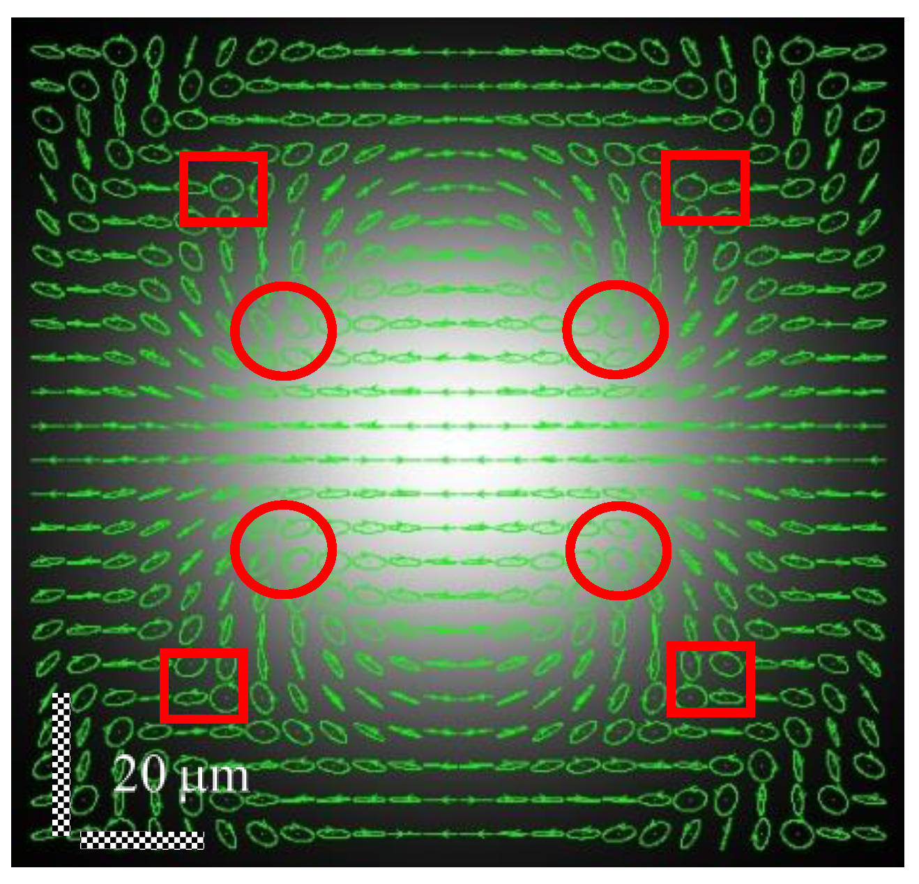
When a linearly polarized beam ( γ = 0 ) propagates along the optical axis of the crystal, the field decomposes, due to diffraction on the crystal lattice, into components with circular polarization, which form the characteristic pattern of polarization features shown in Figure 1. From the map of polarization states shown in Figure 1, it can be seen that the field near the beam axis is linearly polarized. At the same time, the peripheral regions of the field have a complex polarization composition. Four areas close to the axis are clearly distinguished, forming lemon-type polarization singularities [21]. The topological index n of different polarization singularities is additive: a loop taken around multiple singularities will give an index equal to the sum of the indices of the individual singularities. Orientation ambiguity occurs at circular polarization states called C-points. C-points in particular come in three generic types: lemons with index n = + 1 / 2 , stars with index n = 1 / 2 , and monstars with index n = + 1 / 2 . The monstar is a less common transition singularity formed in creation and annihilation events between singularities.
These singularities are located on lines oriented at an angle θ = ± π / 4 to the axis x . Singularities close to them, located on the same line, look like stars. In terms of scalar singularities, regions of the lemon and star types correspond in each component to optical vortices having opposite unit charges.
At C-points, S 1 = S 2 = 0 , and for L-lines, S 3 = 0 [13,21]. Polarization singularities of ellipse as well as vector fields appear as phase singularities in the complex Stokes field S 12 = S 1 + i S 2 , constructed from the Stokes parameters. These singularities are called Stokes singularities, with Stokes singularity index σ 12 . Instead of two indices, namely, the C-point index for ellipse fields and Poincare–Hopf index for vector fields, a single index known as the Stokes singularity index can be used. C-points are phase vortices of topological charge l = ± 1 , and their Stokes singularity index is σ = ± 1 .
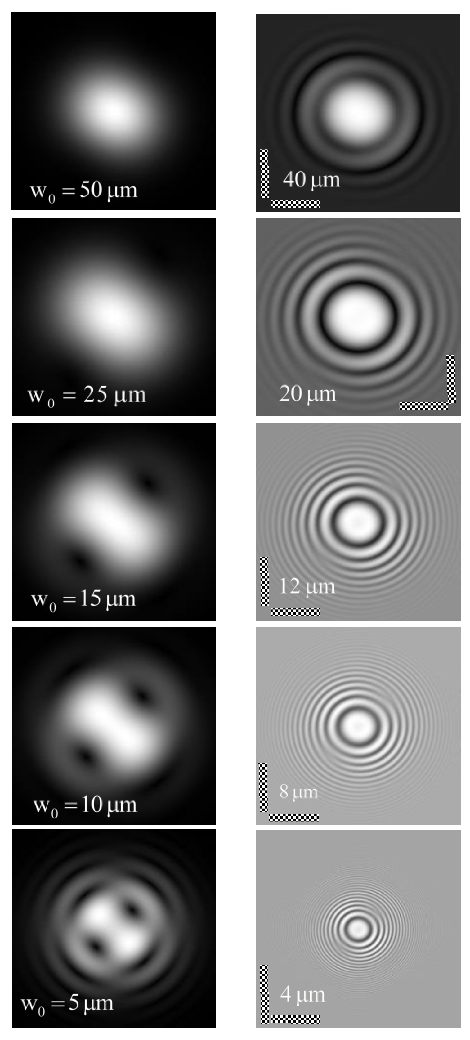
Typical pictures of the distribution of optical vortices in the beam components are shown in Figure 2 and Figure 3. In order to identify the sign of the vortex charge in adjacent columns, interference patterns are shown. Each row in the column corresponds to the original beams with different waist radii. As can be seen from the figures, the structure of singularities in the beam does not depend on its waist, but on the position of optical vortices on rays with charges θ = 45 ° , 135 ° , 225 °   and 315 ° . The smaller the beam waist radius, the closer the position of the optical vortices to the beam axis. It can be concluded from the form of interference patterns that each quadruple of vortices forms a characteristic topological quadrupole for monochromatic [22] and polychromatic [23] beams. The vortices lying on the rays θ = 45 ° , 225 ° and θ = 135 ° ,   315 ° have opposite topological charges. In addition, the optical vortices in the circularly polarized components are specularly reflected with respect to each other. That is, the vortices lying on the same beam have opposite signs of the topological charge.
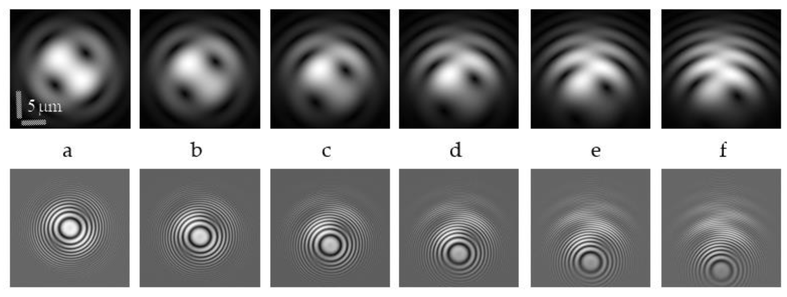
Such a symmetrical distribution of charges in the components has a simple physical meaning: if a beam is observed in a linearly polarized basis, then the complex pattern of vortices in the beams will be replaced by a typical Maltese cross. When the beam is tilted, the pattern of singularities shifts synchronously, as shown in Figure 4.
At large beam inclinations, the combined field do not separate into two separate partial beams, since the extraordinary beam is interferential suppressed, and we observe only an ordinary beam with linear polarization. This beam completely repeats the original Gaussian beam, and all phase and polarization singularities disappear.

3. Structure of the Field of an Inclined Linearly Polarized Laguerre–Gauss Beam

Let us consider the structure of the field of an inclined beam, which is formed from a linearly polarized Laguerre–Gaussian beam with m = 0 , l = 1 , polarized at an angle 90 γ to the plane. It should be noted that the features of the generation of a topological charge ( T C ) based on an anisotropic medium [10,11] are that only in one of the polarization components a beam is created that carries T C = ± 2 (depending on the circulation of the input polarization). If we use a Laguerre–Gauss beam ( T C = + 1 ) incident on the input plane of the crystal at small angles to the z-axis, then in this case we obtain (for different polarization circulations) T C = 1 or T C = 3 , respectively. Using expression (2), we find
E + ( L ) = x i ( y α o z ) w 0 σ o Ψ o + x i ( y α e z ) w 0 σ e Ψ e e i γ x i ( y + α o z o ) x + i ( y + α o z o ) x i ( y α o z ) w 0 σ o Ψ o x i ( y α e z ) w 0 σ e Ψ e e i γ ,
E ( L ) = x i ( y α o z ) w 0 σ o Ψ o + x i ( y α e z ) w 0 σ e Ψ e e i γ x + i ( y + α o z o ) x i ( y + α o z o ) x i ( y α o z ) w 0 σ o Ψ o x i ( y α e z ) w 0 σ e Ψ e e i γ .
For coaxial propagation ( α o = 0 ), the RCP component has a term containing an optical vortex with a negative triple topological charge, while the LCP component contains an optical vortex term with unit negative topological charge. This symmetry of the circularly polarized components of the electric field is essentially manifested in the difference in their oblique propagation in the crystal. Figure 5 illustrates the change in the magnitude of the total intensity in each of the circular components with a change in angle α o , if the angle of inclination is γ = π / 4 .
In contrast to the case of a circularly polarized beam propagating through a crystal, a beam with an initial linear polarization in the z = 2 cm plane has equal intensities of the RCP and LCP components at α o = 0 . Increasing the tilt angle of the initial beam first leads to a rapid decrease in the intensity in the LCP component, while the intensity of the RCP component increases.
It is quite remarkable that the amplitude of the change in intensity is rigidly related to the value of the beam waist radius w 0 . The smaller the beam waist radius, the smaller the initial amplitude. For example, for a beam with a waist radius w 0 = 10 μ m (Figure 5a), the maximum deviation of the normalized intensity I n o r m = 0.5 from the average value ( Δ I ) is Δ I max = I n o r m Δ I = 0.15 . By the normalized intensity ( I n o r m ) value we mean the ratio of the intensity value I α measured at an angle to the highest (maximum) intensity value I α max : I n o r m = I ( α ) / I ( α max ) . At the same time, the maximum deviation from the initial value in the intensities of the components for a beam with a waist radius w 0 = 50 μ m (Figure 5c) reaches the value Δ I max = 0.45 . Since the RCP and LCP intensity fluctuations are in antiphase for beams with a relatively large waist radius ( w 0 = 50 μ m ) already for the angle α o = 0.5 ° (see Figure 5), the intensity in the RCP component practically doubles, while the intensity in the LCP becomes vanishingly small. In fact, there is a conversion between LCP and RCP polarization. At the same time, for beams with a relatively small waist radius ( w 0 = 10   μ m ), the intensity fluctuations are very small.
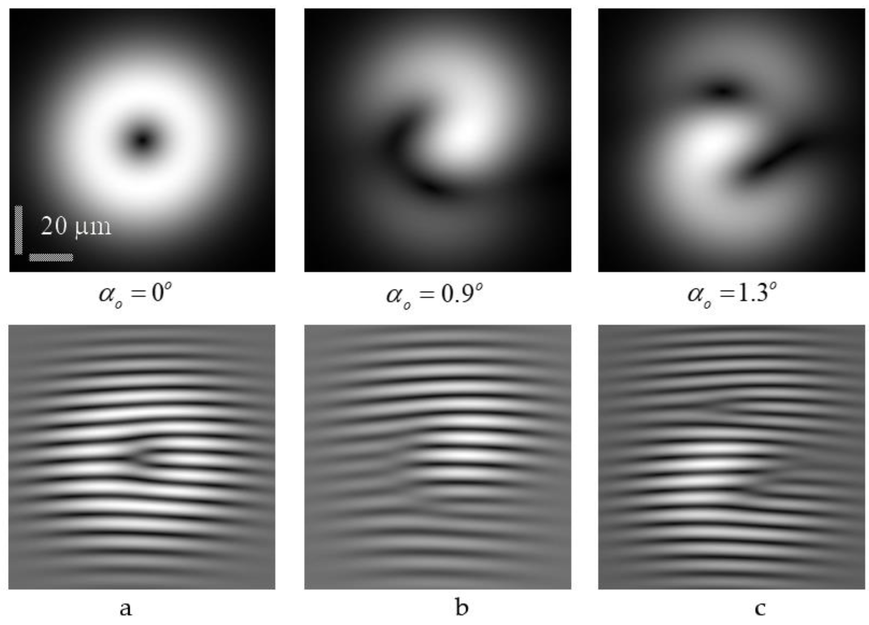
Such a difference in the conversion of polarizations in inclined beams with different waists cannot but affect the evolution of polarization and scalar singularities in the beam components. Figure 6 shows the intensity distributions and interference patterns for a beam with a waist radius w 0 = 4 μ m for the LCP and RCP components. The picture clearly shows two chains of optical vortices (Figure 6a), located along the rays θ = 0 ° , 90 ° , 180 ° , 270 ° . As in the case of linear polarization with γ = 0 , unit vortices along each ray have alternating signs of topological charges. The axial vortex has a charge equal to l = 1 , and the vortices closest to it, located along the axis O y , have charges l = 1 . When the beam is tilted in the plane y O z , at first glance it seems that the pattern of singularities should shift down along the axis O y ; in this case, the axial optical vortex must slip off the beam axis, and its place must be taken by a vortex with the opposite topological charge, and so on. However, in reality, the picture of vortex evolution in each beam component is much more complicated.
As can be seen from Figure 6d–f, the structure of an RCP component is very different from an LCP component. From the comparison of interference patterns Figure 6a,d, it can be seen that the charges of the axial vortices are the same, but the vortices in the first ring have opposite charges. When changing the angle α o , the unfolding zones for different components fall at different angles: for LCP components, on α o = 0.6 ° (Figure 6b), for RCP, on α o = 0.9 ° (Figure 6f). The entire complexity of the situation is already manifested in the example of beams with a relatively large waist radius w 0 = 50 μ m (see Figure 7).
Thus, in the case of coaxial beam propagation, we observe an almost symmetrical intensity distribution with a centered optical vortex. All peripheral vortices disappear. When the beam is tilted, a number of topological reactions occur, which lead to a radical structural rearrangement of the entire beam. Under the concept of the topological reaction of optical vortices in an anisotropic sheaf, we mean the addition or subtraction (annihilation) of the topological charge of a given beam. As we can see from the comparison of two similar processes (Figure 6 and Figure 7), the structural transformations in them are fundamentally different.

4. Polarization Unfolding and Doubling of Scalar Singularities

4.1. Polarization Unfolding at γ = 45

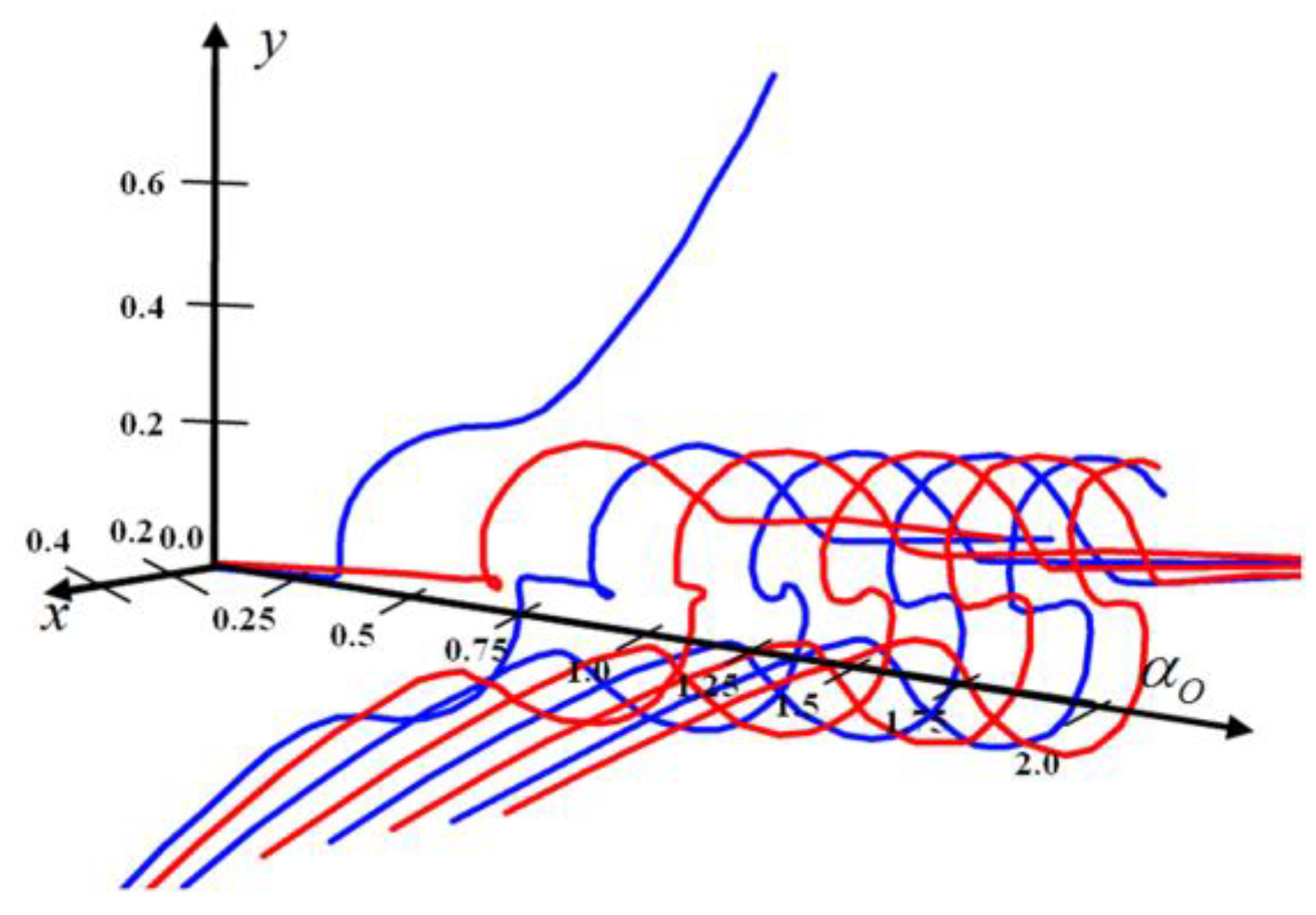
To understand the processes of evolution of polarization and phase singularities in a linearly polarized beam, let us consider the form of C-lines for beams with a relatively large w 0 = 50 μ m , which is shown in Figure 8 for the case of input polarization tilt relative to the beam tilt plane γ = 45 ° .
As in the case of excitation of a crystal by a beam with circular polarization, for linear polarization we can distinguish four main sections of the trajectory in which the structure of the lines and the course of topological reactions are different: (1) the initial section in the vicinity of the angle α o 0 ° ; (2) an intermediate section up to the region of critical angles; (3) the region of critical angles; and (4) asymptotic region at relatively large angles α o or large crystal lengths z . Figure 8 corresponds to the first two corner sections. As can be seen from the figure, regarding value α o 0.7 ° , before, the changes in the trajectories are quite small, but after this angle, the number of trajectories of C-points increases, and the trajectory becomes much more complicated.
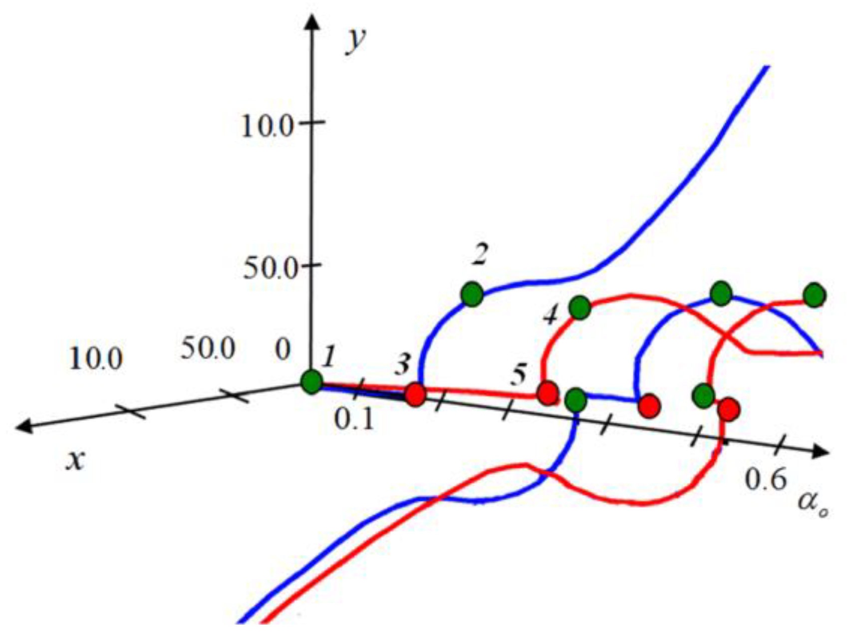
In the area near the axial propagation ( α o = 0 ) of the beam, the pattern of C-lines is shown in Figure 9.
To understand the structure of the C-lines in the initial section, let us first turn to the distribution of the states of the field polarization. An optical vortex is located on the beam axis, which is a degenerate state in the form of a field with linear polarization, which lies at the point of intersection of two L-lines. These two L-lines are separated by four “lemons” located a little farther from the beam axis. Note that the total topological index of this system, taking into account the sign of the polarization circulation, must be equal to the topological index of the scalar field (topological charge l = 1 ). Lemons have a topological index s = 1 / 2 . In the peripheral region are two RCP lemons and two LCP lemons. Therefore, the full index [21] is:
S = 1 / 2 1 / 2 1 / 2 ( 1 ) 1 / 2 ( 1 ) + ( 1 ) = 1 .
With a small beam tilt, four lemons are slightly shifted down in the beam tilt plane. At the same time, the degenerate state at the point of intersection of two L-lines on the beam axis splits into two singular points—a lemon and a star with opposite circular polarizations (star topological index). The total topological index of the sheaf is:
S = 1 / 2 1 / 2 1 / 2 ( 1 ) 1 / 2 ( 1 ) [ 1 / 2 1 / 2 ( 1 ) ] = 1 .
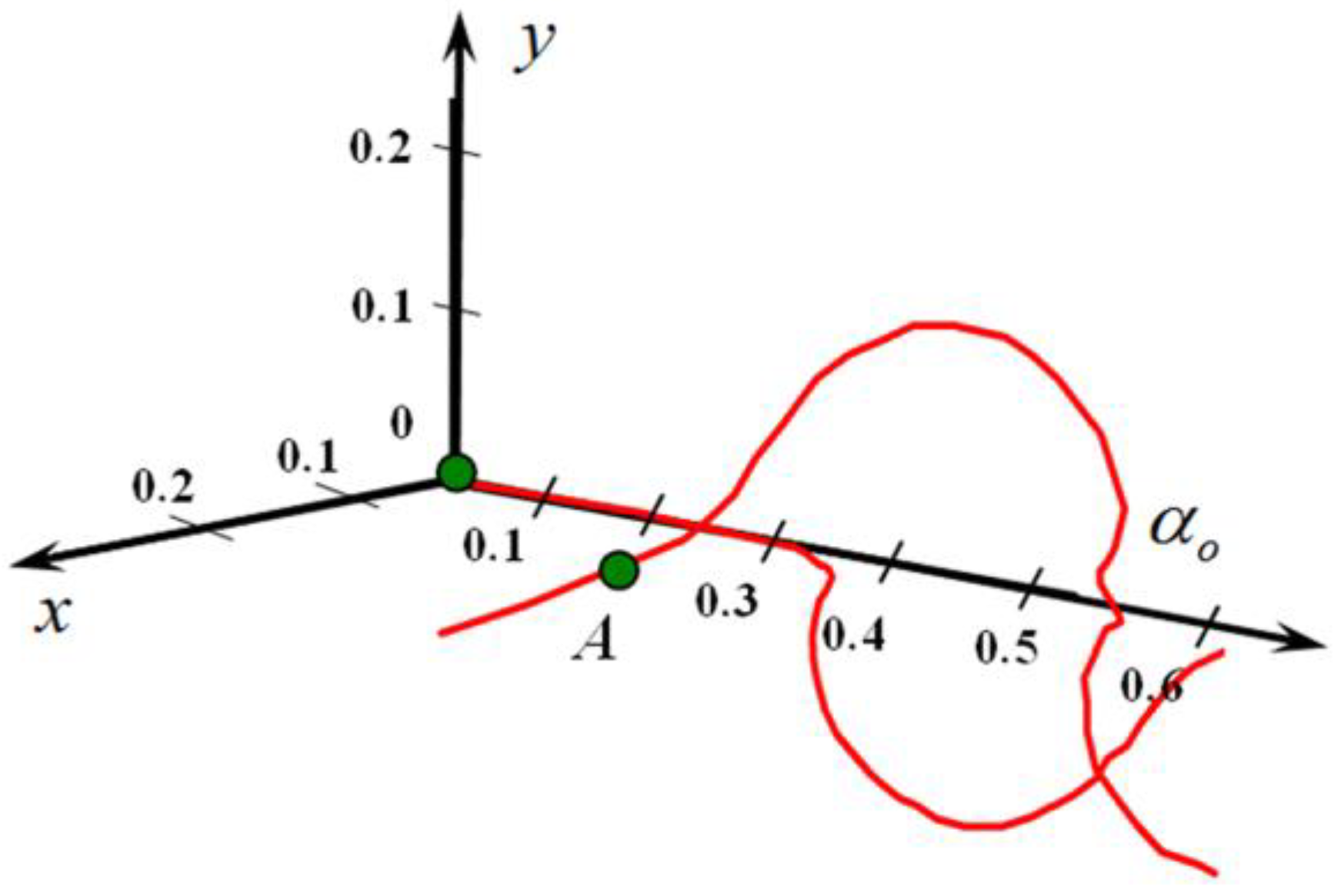
Thus, the tilt of the beam will not change the overall topological index of the system. Returning to Figure 9 we see that a lemon and a star are born near the axis at point 1, corresponding to the linearly polarized initial vortex. As the angle increases, near the beam axis at point 2, a lemon–star pair is born, which corresponds to the topological dipole of vortices in the LCP component. The singularities of this pair move in opposite directions: the lemon approaches the paraxial star and annihilates with it at point 3 (the point of polarization unfolding), while the star of the dipole pair is forced out to infinity. Thus, a lemon (red line) remains in the beam near the axis, which corresponds to a vortex with a negative topological charge. There is a sign switching of the circulation of polarization singularities, but the signs of charges in the circularly polarized components have not changed. Further, at point 4 on the red trajectory, a lemon–star dipole pair is again born, corresponding to the topological dipole in the RCP component, and at point 5, the process is repeated. This process corresponds to the annihilation of the circular polarization and, on the whole, looks like a switch in the circulation direction along one of the C-lines. Just a simplified version of such an unfolding is discussed in [16,17]. In the future, this process is regularly repeated. In fact, such a process corresponds to the annihilation of an optical vortex with a negative charge in one component and the appearance of the same vortex in another component [19,20]. This process can be considered as an exchange of optical vortices between circularly polarized components, in which the conservation law of the total topological index is satisfied, and the magnitude and sign of the optical vortex involved in the exchange does not change.

4.2. Doubling of Scalar Singularities at γ = 45 °

In fact, if one follows the evolution of optical vortices in each of the circularly polarized components, then a situation arises when, in the entire section of the paraxial trajectory, an optical vortex is absent in the circularly polarized component but appears in another component. This effect of the exchange of optical vortices between the components is characteristic of the entire intermediate segment of the trajectories of polarization and scalar singularities. However, the course of this process changes if the sign of the slope of the linear polarization at the entrance to the crystal is reversed ( γ = 45 ° γ = 45 ° ).
Indeed, referring to Figure 10 for the RCP component propagating along the optical axis of the crystal, we see that the signs of the peripheral vortices along the direction O y have changed.
It can be assumed that when the beam is tilted in the plane, the axial y O α o vortex at certain angles will encounter vortices with identical signs of topological charges, and at first glance, instead of unfolding, we should obtain a doubling of the topological charge on the axis in certain planes of the crystal. To find out the correctness of such an assumption, it is necessary to study the evolution of the fine structure of scalar singularities. By the concept of fine structure [21], we mean not only the polarization structure (C-lines and L-surfaces), but also the structure of the topological charge of a singular beam. A characteristic interference pattern in the region of convergence of vortices with the same charge signs is shown in Figure 11.
The interference pattern in Figure 11b, for beams with a waist radius w 0 = 10 μ m , illustrates a double helix characteristic of vortices with a double topological charge. For comparison, in Figure 11c,d the picture of annihilation in the same plane is shown. To verify the fact of vortex doubling on a macroscopic scale, we plotted the trajectories of optical vortices in the RCP in this section for a beam with a waist radius of w 0 = 50 μm. The corresponding trajectory is shown in Figure 12.
We see that the axial vortex in the RCP component propagates without external disturbances at small tilt angles. As it approaches the polarization singularity unfolding plane at γ = 45 ° (see Figure 12), a dipole pair of vortices is born near the axis at point A (green circle); one of them quickly moves away from the beam axis, and the second negatively charged vortex approaches the axial one and the negatively charged vortex. However, as it approaches, repulsion of the trajectories occurs. Therefore, a vortex with a double topological charge l = 2 does not arise. However, at the same time, a vortex propagates along the axial trajectory in the LCP component, creating the appearance of polarization unfolding. In contrast to the case of the polarization tilt angle γ = 45 ° , where true unfolding occurs, accompanied by the event of vortex annihilation in one of the components, in the case of γ = 45 ° the vortices do not annihilate in one of the components, but simply leave the beam. Therefore, polarization unfolding as such does not occur.
Such a process of exchange of optical vortices between orthogonally polarized components near L-surfaces is characteristic of the entire zone of intermediate angles. In fact, the above-described exchange processes are alternately repeated up to the critical angle.
It is important to note that in the case of the initial linearly polarized beam, it is impossible to divide the trajectories into two types: longitudinal (the main trunk of the trajectory) and transverse, as was the case when the crystal was excited by a circularly polarized beam. Switching the polarization circulation in the unfolding planes eliminates such splitting. Part of the trajectories of vortices in linearly polarized beams is transverse, while the central parts of each trajectory are almost parallel to the axis of the original beam.

4.3. Splitting Singular Beams

Thus, the trajectory has a mixed character up to critical angles. When the tilt angle of the initial beam axis reaches the critical angle, the trajectory structure changes significantly.
Figure 13 shows two types of trajectories for RCP (Figure 13a) and LCP (Figure 13b) beams in the vicinity of the critical angle. At the critical angle [24,25], the lateral branch of the trajectory gradually bends, forming the trunk of the second beam. The next branch of the trajectory also bends, forming the stem of the first beam. The shape of both stem trajectories resembles a spiral. In this case, the direction of twisting of the spirals for both RCP and LCP is the same, and the trajectories of these polarization points are symmetrical. The critical angle conditions remain the same as for beams with the initial circular polarization.

5. Conclusions

This paper shows that the distribution of optical vortices in the circularly polarized components of the original linearly polarized Laguerre–Gauss beam is devoid of axial symmetry even in the case of coaxial propagation. Therefore, the evolution of both scalar and polarization singularities is different for the initial linear polarization oriented at angles γ = 45 ° and γ = 45 ° . The same difference takes place for different beam tilt planes.
When the beam is tilted in the γ = 45 ° or γ = 45 ° planes, an exchange of vortices between the orthogonal components of the beam is observed, provided that the magnitude and sign of the topological charge are preserved. The exchange of vortices is accompanied by a chain of topological reactions, which consist in the fact that paraxial vortices in the circularly polarized components of the beam either annihilate alternately or are abruptly forced out to infinity. The process of annihilation of vortices is typical for the orientation of linear polarization at an angle γ = 45 ° , and the process of displacement of vortices is typical for an angle γ = 45 ° .
The method described in this article can be applied by other researchers to analyze the properties of spin and orbital moments in free space [26], to analyze the shapes and properties of beams that carry a topological charge, to study anisotropic media [27], and to study the properties of topological charges [28] both in anisotropic media and in weakly turbulent atmospheric media.
The results obtained in this publication can be used in modern photonics, for example, to develop improved configurations of the shape and types of optical beams, to find states (C-lines and L-surfaces) of polarization of anisotropic media that cannot be created by other means, and to overcome any technical limitations associated with the improvement of design instruments and apparatuses, including those for medical research.

Author Contributions

Conceptualization, Y.E. and A.R.; methodology, Y.E.; validation, Y.E. and A.R.; formal analysis, Y.E. and A.R.; investigation, Y.E. and A.R.; resources, Y.E. and A.R.; writing—original draft preparation, Y.E.; writing review and editing, Y.E. and A.R.; supervision, Y.E.; project administration, Y.E. and A.R. All authors have read and agreed to the published version of the manuscript.

Funding

This research received no external funding.

Institutional Review Board Statement

Not applicable.

Informed Consent Statement

Not applicable.

Data Availability Statement

The data presented in this study are available upon request from the respective author.

Conflicts of Interest

The authors declare no conflict of interest.

References

  1. Berry, M.V. Optical vortices evolving from helicoidal integer and fractional phase steps. J. Opt. 2004, 6, 259–268. [Google Scholar] [CrossRef]
  2. Soifer, V.A.; Golub, M.A. Laser Beam Mode Selection by Computer-Generated Holograms; CRC Press: Boca Raton, FL, USA, 1994; p. 215. ISBN 978-0-8493-2476-5. [Google Scholar]
  3. Basistiy, I.V.; Bazhenov, V.Y.; Soskin, M.S.; Vasnetsov, M.V. Optics of light beams with screw dislocations. Opt. Commun. 1993, 103, 422–428. [Google Scholar] [CrossRef]
  4. Allen, L.; Paget, M.; Babiker, M. The Orbital Angular Momentum of Light. Prog. Opt. 1999, 39, 291–333. [Google Scholar] [CrossRef]
  5. Bliokh, K.Y. Spatiotemporal Vortex Pulses: Angular Momenta and Spin-Orbit Interaction. Phys. Rev. Lett. 2021, 126, 243601. [Google Scholar] [CrossRef] [PubMed]
  6. Bryngdahl, O. Radial- and circular-fringe interferograms. J. Opt. Soc. Am. 1973, 63, 1098–1104. [Google Scholar] [CrossRef]
  7. Beijersbergen, M.W.; Coerwinkel, R.P.C.; Kristensen, M.; Woerdman, J.P. Helical-wavefront laser beams produced with a spiral phaseplate. Opt. Commun. 1994, 112, 321–327. [Google Scholar] [CrossRef]
  8. Kotlyar, V.V.; Kovalev, A.A.; Porfirev, A.P. Vortex Laser Beams, 1st ed.; CRC Press: Boca Raton, FL, USA, 2018; p. 418. [Google Scholar] [CrossRef]
  9. Kotlyar, V.V.; Kovalev, A.A.; Kalinkina, D.S.; Kozlova, E.S. Fourier-Bessel beams of finite energy. Comput. Opt. 2021, 45, 506–511. [Google Scholar] [CrossRef]
  10. Ciattoni, A.; Cincotti, G.; Palma, C. Circularly polarized beams and vortex generation in uniaxial media. J. Opt. Soc. Am. A 2003, 20, 163–171. [Google Scholar] [CrossRef]
  11. Volyar, A.V.; Egorov, Y.A.; Rubass, A.F.; Fadeeva, T.A. Fine structure of white optical vortices in crystals. Tech. Phys. Lett. 2004, 30, 701–704. [Google Scholar] [CrossRef]
  12. Athira, B.S.; Mukherjee, S.; Laha, A.; Bar, K.; Nandy, D.; Ghosh, N. Experimental observation of the orbital Hall effect of light through pure orbit–orbit interaction for randomly and radially polarized vortex beams. J. Opt. Soc. Am. B 2021, 38, 2180–2186. [Google Scholar] [CrossRef]
  13. Born, M.; Wolf, E. Principles of Optics; Pergamon Press: Tarrytown, NY, USA, 1980; p. 836. ISBN 9781483103204. [Google Scholar]
  14. Vlokh, R.; Mys, O.; Romanyuk, M.; Girnyk, I.; Martunyuk-Lototska, I.; Czapla, Z. Optical Characterization of Organic-Inorganic [(CH2OH)3CNH3)]H2PO4 Crystals. Ukr. J. Phys. Opt. 2005, 4, 133–135. [Google Scholar] [CrossRef]
  15. Cincotti, G.; Ciattoni, A.; Sapia, C. Radially and azimuthally polarized vortices in uniaxial crystals. Opt. Commun. 2003, 220, 33–40. [Google Scholar] [CrossRef]
  16. Flossmann, F.; Schwarz, U.T.; Maier, M.; Dennis, M.R. Polarization Singularities from unfolding an optical vortex through a Birefringent Crystal. Phys. Rev. Lett. 2005, 95, 253901. [Google Scholar] [CrossRef] [Green Version]
  17. Flossmann, F.; Schwarz, U.T.; Maier, M.; Dennis, M.R. Stokes parameters in the unfolding of an optical vortex through a birefringent crystal. Opt. Express 2006, 14, 11402–11411. [Google Scholar] [CrossRef] [Green Version]
  18. Craciun, A.; Grigore, O.V. Superposition of vortex beams generated by polarization conversion in uniaxial crystals. Sci. Rep. 2022, 12, 8135. [Google Scholar] [CrossRef]
  19. Fadeyeva, T.A.; Rubass, A.F.; Volyar, A.V. Transverse shift of a high-order paraxial vortex-beam induced by a homogeneous anisotropic medium. Phys. Rev. A 2009, 79, 053815. [Google Scholar] [CrossRef] [Green Version]
  20. Fadeyeva, T.A.; Rubass, A.F.; Volyar, A.V. The matrix model of the vortex-beam quadrefringence in a uniaxial crystal. Ukr. J. Phys. Opt. 2009, 3, 109–123. [Google Scholar] [CrossRef]
  21. Nye, J.F. Natural Focusing and Fine Structure of Light: Caustics and Wave; Institute of Physics Publishing: Bristol, UK, 1999; p. 328. ISBN 0750306106. [Google Scholar]
  22. Volyar, A.V.; Fadeeva, T.A. Dynamics of topological multipoles: I. High-order nonparaxial singular beams. Opt. Spectrosc. 2002, 92, 243–252. [Google Scholar] [CrossRef]
  23. Egorov, Y.; Rubass, A. Spin-Orbit Coupling in Quasi-Monochromatic Beams. Photonics 2023, 10, 305. [Google Scholar] [CrossRef]
  24. Fadeyeva, T.; Egorov, Y.; Rubass, A.; Swartzlander, G.A.; Volyar, A. Indistinguishability limit for off-axis vortex beams in uniaxial crystals. Opt. Lett. 2007, 32, 3116–3118. [Google Scholar] [CrossRef]
  25. Fadeyeva, T.; Egorov, Y.; Rubass, A.; Volyar, A.V. Quadrefringence of optical vortices in a uniaxial crystal. J. Opt. Soc. Am. A 2008, 25, 1634–1641. [Google Scholar] [CrossRef] [PubMed] [Green Version]
  26. Volyar, A.V.; Bretsko, M.V.; Akimova, Y.E.; Egorov, Y.A. Avalanche instability of the orbital angular momentum higher order optical vortices. Comput. Opt. 2019, 43, 14–24. [Google Scholar] [CrossRef]
  27. Volyar, A.V.; Fadeeva, T.A.; Egorov, Y.A. Vector singularities of Gaussian beams in uniaxial crystals: Optical vortex generation. Tech. Phys. Lett. 2002, 28, 958–961. [Google Scholar] [CrossRef]
  28. Volyar, A.V.; Abramochkin, E.G.; Egorov, Y.A.; Bretsko, M.V.; Akimova, Y.E. Digital sorting of Hermite-Gauss beams: Mode spectra and topological charge of a perturbed Laguerre-Gauss beam. Comput. Opt. 2020, 44, 501–509. [Google Scholar] [CrossRef]
Figure 1. Polarization distribution for a linearly polarized beam γ = 0 . For a crystal thickness z = 2 c m , beam waist radius w 0 = 10 μ m , and beam tilt angle α o = 0 ° . Circles correspond to lemons, squares to stars.
Photonics 10 00684 g001
Figure 2. Intensity distribution and phase structure of a coaxial linearly polarized Gaussian beam at different waist radii in the RCP component.
Photonics 10 00684 g002
Figure 3. Intensity distribution and phase structure of a coaxial linearly polarized Gaussian beam at different waist radii in the LCP component.
Photonics 10 00684 g003
Figure 4. Displacement of singularities at tilt of the beam axis in the RCP component, beam waist radius w o = 5 μ m , crystal thickness z = 2 c m at an angle of inclination (a) α o = 0 ° ; (b) α o = 0.2 ° ; (c) α o = 0.4 ° ; (d) α o = 0.6 ° ; (e) α o = 0.8 ° ; and (f) α o = 1 ° .
Photonics 10 00684 g004
Figure 5. The dependence of the intensity of the RCP (red) and LCP (blue) components for different beam waist radii w o , for the crystal length z = 2 c m , (a) w o = 10 μ m ; (b) w o = 25 μ m ; and (c) w o = 50 μ m .
Photonics 10 00684 g005
Figure 6. Intensity distribution of a linearly polarized beam γ = π / 4 , with a change in tilt angles α o , crystal length z = 2 cm, in the LCP component (ac), and in the RCP component (df).
Photonics 10 00684 g006
Figure 7. Structure of the intensity distribution and interference pattern (ac) for a Laguerre–Gauss beam with a waist of w 0 = 50 μ m and a crystal length of z = 2 cm in the RCP component.
Photonics 10 00684 g007
Figure 8. The trajectory of C-points at small angles, depending on the angle of inclination, for a crystal with a length of z = 2 cm, w 0 = 50 μ m . RPC—red, LPC—blue.
Photonics 10 00684 g008
Figure 9. The trajectory of C-lines at small angles, depending on the angle of inclination, for a crystal with a length of z = 2 cm, w 0 = 50 μ m , RPC—red, LPC—blue.
Photonics 10 00684 g009
Figure 10. Change in the field structure upon rotation of the input polarization γ = 45 ° (a,b) γ = 45 ° (c,d) for a beam with a waist radius of w 0 = 8 μm that has passed through a crystal with a length of z = 2 cm.
Photonics 10 00684 g010
Figure 11. Doubling of the topological charge (a,b) at γ = 45 ° , and annihilation of the optical vortex (c,d) at γ = 45 ° for a crystal of length z = 2 cm and tilt angle α o = 0.37 ° , with a beam waist radius w 0 = 10 μm.
Photonics 10 00684 g011
Figure 12. Trajectory of the C-point in the RCP component for a beam with beam waist radius w 0 = 50 μ m , for a crystal length z = 2 cm.
Photonics 10 00684 g012
Figure 13. Behavior of trajectories in the vicinity of the critical angle for RCP (left) and LCP (right) for a crystal z = 2 cm long and beam waist radius w 0 = 50 μm.
Photonics 10 00684 g013
Disclaimer/Publisher’s Note: The statements, opinions and data contained in all publications are solely those of the individual author(s) and contributor(s) and not of MDPI and/or the editor(s). MDPI and/or the editor(s) disclaim responsibility for any injury to people or property resulting from any ideas, methods, instructions or products referred to in the content.