Abstract
In the optical fiber time transfer system, fiber optic time transfer is limited by the pulse signal time delay measurement precision, and cannot benefit from a higher precision of the carrier phase information. Its transfer precision compared to the frequency transfer exists in a larger gap transfer. This paper proposes a time delay measurement method based on carrier phase and pseudo-code ranging for optical time transfer. The time signal is modulated with pseudo-random code and carrier at the transmitter, and the time delay is measured at the receiver by the methods of pseudo-code ranging and carrier phase measurement. The time transfer is achieved by eliminating the transmission link delay through a two-way method. The first-order difference value of the carrier phase measurement and the pseudo-code ranging measurement are used as the observation quantities, and they are fused through a Kalman filtering method to finally obtain the high-precision time difference measurement. We validate the theory on the common-clock experimental platform over a 50 km fiber link, The time transfer stabilities of the systems are /s and / s (modified Allan deviation), /s and / s (time deviation). The standard deviation of the time transfer system after fusion can reach 2.4255 ps.
1. Introduction
As one of the seven basic physical quantities, time has the highest measurement precision, and the measurement of other physical quantities can usually be converted into the measurement of time. At present, the stability of the optical clock has reached the level of 2 × 10 [1]. How to transmit the high-precision time signal generated by the clock is of great significance for global satellite navigation systems [2,3,4], atomic clock group time comparison [5], deep space exploration [6] and other fields. The traditional satellite-based common view method [7] and satellite bidirectional time–frequency transmission method [8,9] are greatly affected by the environment and have limited precision. It can no longer meet the increasing precision requirements. Compared to traditional satellite-based wireless time transfer methods, fiber optical time transfer has the characteristics of high precision and strong anti-interference ability. So it has become a key research topic in the field of time transfer. Multiple international laboratories have conducted research based on fiber optic time transfer technology [10,11,12,13,14,15,16,17].
At present, the main methods of time transfer based on optical fibers are optical time transfer based on white rabbit time synchronization network [18]; optical fiber bidirectional time transfer based on optical amplitude modulation 1 pulse per second (1 PPS) time signal [19]; optical bidirectional time transfer based on optical amplitude modulation pseudo-random code [20]. Optical time transfer over a white rabbit network requires transmission over a dedicated white rabbit time synchronization network with limited precision. The synchronization precision can only reach sub-nanoseconds, so it is often used for networked time synchronization that does not require high precision. There are two problems in the optical bidirectional time transfer method based on optical amplitude modulation for 1 PPS time signal. Firstly, the time interval counter used for the 1 PPS time signal measurement has a measurement precision of 25 ps, which can no longer meet the requirements of high-precision time transfer. Secondly, the time signals transmitted in both directions need to be modulated to different wavelengths to prevent backscattering from deteriorating the short-term stability of time transmission. Due to the dispersion and birefringence effects of optical fibers, different wavelengths can cause asymmetry of two-way delays [21]. Moreover, for long-distance transmission, the compensation for asymmetric delay is complex and difficult to achieve. Chen Zufeng et al. proposed a single-fiber time-division multiplexing bidirectional time transfer method [22], which simplifies the compensation structure and improves the transfer precision due to the bidirectional transfer using the same wavelength optical carrier and avoiding the noise of backward scattering by time-division multiplexing, which does not need to compensate for the fiber link but only needs to calibrate the site equipment. However, the time-division multiplexing method requires time synchronization of the time transfer equipment, and is not applicable to multi-site time transfer.
The optical fiber time transfer method based on optical amplitude modulation pseudo-random codes allows two-way transmission of signals using the same wavelength at the same time by assigning different pseudo-codes, avoiding the dispersion effect caused by different light wavelengths. However, the measurement precision that can be achieved by using the pseudo-range measurement method is limited, and the higher-frequency carrier cannot be used to achieve higher-precision measurement. M Rost et al. [20] connected two satellite bidirectional time–frequency devices at different locations over dark fiber, and due to the advantage of the large fiber optic bandwidth, a code rate of 20 MHz was used to transmit pseudo-random codes to achieve the highest precision. After calibration, time transfer with an uncertainty of less than 100 ps was achieved over 73 km of optical fiber, and carrier phase measurements have higher measurement precision than pseudo-code phase measurements.However, the measurement value of the carrier phase has integer ambiguity; when using carrier phase measurements for time transfer, the integer ambiguity needs to be determined first. Time transfer techniques based on carrier phase measurements have been widely used for satellite time and frequency synchronisation [23,24,25]. But it has not been applied in the field of optical fiber time transmission.
In this paper, a high-precision clock difference measurement method in the optical fiber time transfer system based on a Kalman filter is proposed. The pseudo-range measurement value and carrier phase measurement value are obtained at the receiver through the tracking loop. The pseudo-range measurement value and the first-order difference component of the carrier phase are taken as the observation values, then the Kalman filter equation is established. We obtain smooth and precise clock deviation measurements through filtering, and realize high-precision fiber optic time transmission finally.
2. Theory
2.1. Fiber Optical Time Transfer System
There are two stations in the optical time transfer system, one is the receiver and the other is the transmitter, they have a fully symmetrical structure and eliminate link transmission delay through two-way transfer. A structure diagram of the system is shown in Figure 1. Clock sources A and B provide the reference frequency signal and 1 PPS time signal for the receiver and transmitter, respectively. The receiver generates the pseudo-random code and carrier wave through the clock signal provided by the clock source. After the pseudo-random code modulation and carrier modulation, the time transfer signal is converted from an electrical signal to an optical signal by the laser, whose central wavelength is 1550 nm. The optical signals are transmitted in both directions via a single fiber loop. After transmission over the fiber optic link, the optical signal is reconverted into an electrical signal by means of a photodetector at the receiver end. The pseudo-range and carrier phase measurement values are obtained by means of a pseudo-range measurement unit and a carrier phase measurement unit. The pseudo-range and carrier phase measurement values then include the transmission delay and the clock difference between the two sites.
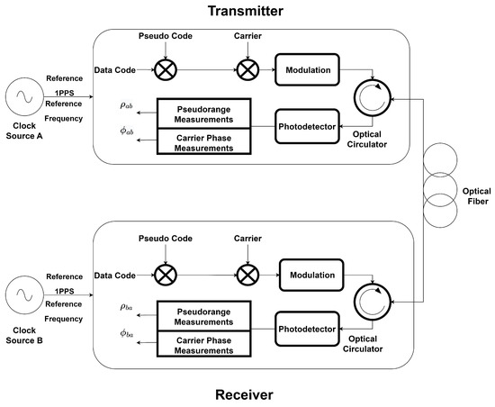
Figure 1.
Structure diagram of optical fiber time transfer equipment.
The pseudo-range measurement equation can be expressed using the following formula, where and are the pseudo-range measurement values. and are the pseudo-code transmission delays of station A and station B. At the same time, and are the pseudo-code receiver delays of station A and station B. and are the clock differences between the two stations. and are the pseudo-code transmission delays of the optical fiber link. and are the noise of the pseudo-range measurements.
The pseudo-range measurements of the clock difference are as follows
The carrier phase measurement equation can be expressed using the following formula, where and are the carrier phase measurements, and are the carrier transmission delays of station A and B, and and are the carrier reception delays of station A and B. and are the carrier transmission delays on the optical link. and are the carrier phase measurement noise. and are the integer ambiguities of the carrier phase measurements. is the carrier cycle.
The carrier phase clock difference measurements are as follows:
The optical bidirectional link has a symmetrical time delay and high stability, the receiver transmitter signal processing time delay is precisely calibrated and compensated and has a high stability. The measurement error of clock deviation mainly comes from the noise of pseudo code ranging and carrier phase measurement. Formulas (3) and (6) can be simplified as follows:
2.2. Analysis of Code Phase and Carrier Phase Measurement Precision
The pseudo-random code is modulated by binary phase shift keying (BPSK), the code tracking loop replicates the pseudo-code with the same phase as the received pseudo-code through the numerically controlled oscillator (NCO), and the code phase measurement value of the received signal is obtained according to the control parameter of the NCO, in the fiber optic channel, without considering the interference; the time transfer station is relatively fixed, without considering the measurement error brought by the dynamic stress. Code phase measurement errors are mainly caused by thermal noise from the link transmission and reception equipment. The code phase measurement error equation is shown below [26]. is the code tracking loop noise bandwidth, is the carrier ratio of the received signal, T is the coherent integration time, is the front-end bandwidth, and is a code slice width.
Assuming that the loop bandwidth of the tracking loop is 2 Hz, the coherent integration time is 2 ms, and the front-end bandwidth is 50 MHz, BPSK-m means the code rate is m times 1.023 MHz. The precision of the code phase measurement error is shown in Figure 2.
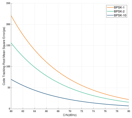
Figure 2.
Measurement error of the code phase.
As shown in Figure 2, under the same carrier to noise ratio conditions, as the bit rate increases, the measurement accuracy also improves. However, due to the limited processing bandwidth of the receiver front-end, the bit rate cannot be infinitely increased, which limits the accuracy of the pseudo code ranging method.
The measurement error of the carrier phase is generated by the carrier loading loop of the carrier trace loop. In the optical fiber time transfer system, the position between the sites is relatively fixed, and the transmission delay of the link will not fluctuate excessively. Therefore, the carrier phase measurement error is mainly caused by thermal noise like the code phase measurement error.
Assuming that the circular band width of the carrier tracking ring is 10 Hz and the relevant points time is 2 ms, the measuring value error of the carrier phase is shown in the figure below.
As shown in Figure 3, the precision of carrier tracking can reach one ten-thousandth of a whole cycle when the carrier noise ratio condition is 75 dBHz; When the carrier frequency is up to GHz, the measurement precision of the carrier phase can reach sub-picoseconds, which is two orders of magnitude higher compared to the pseudo-code measurement precision under the same carrier-to-noise ratio condition.
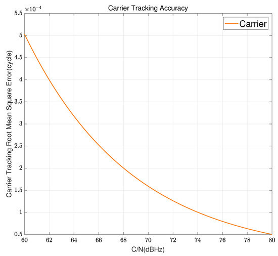
Figure 3.
Measurement error of the carrier phase.
3. Kalman Filter Error Smoothing for Carrier Phase and Pseudo-Range Measurements
The time delay can be calculated using the carrier phase observation and pseudo-code ranging observation. There is no integer ambiguity for the pseudo-code measurement, but the measurement noise is too high. Carrier phase measurements have a high measurement precision, but there is an integer ambiguity, the values of and are unknown. The time delay measurement cannot be directly obtained from the carrier phase measurement value. Therefore, it is necessary to combine the carrier phase with the pseudo-code ranging measurement to obtain a high-precision, non-ambiguous clock difference measurement in an optical time transfer system.
Assuming the observed value of the pseudo-code range for the time delay is , the derivative at
Assuming the observed value of the carrier phase for the time delay is (t), the derivative at t
The physical meaning of the pseudo-range observation and the derivative of the carrier phase is the same, both reflecting the variation in the time delay.
So, the following formula can be derived.
From the above equation, it can be seen that the time delay measurement value at the next time can be calculated from the pseudo-range measurement value at the previous time and the change in the carrier phase during this time interval. Compared to pseudo-range measurements, carrier phase measurements have a higher stability. Therefore, we can use the first-order differential data of carrier phase observations as the variation in clock deviation within the sampling interval to improve the precision of the clock deviation measurement. By using the Kalman filtering method to fuse the pseudo-range measurement value and carrier phase measurement value, a highly stable and unambiguous clock error measurement result is output for high-precision time transfer between systems.
The state equation is established as follows:
The measurement equation is established as follows:
In the formula above, k represents the observation time and is the estimated state. . is a time delay measurement result. is the average rate of change in the time delay. A is the state transition matrix, . is the sampling interval for the time delay measurement. is an observation, ; H is the observation matrix, , is the state excitation noise, is the time delay measurement noise. Assuming that and are white noise that conforms to a normal distribution.
Q is the covariance matrix of state excitation noise. . R is the covariance matrix of the measured noise, . Q and R have different values in different time transfer links, and selecting appropriate parameters can make the filtering value converge faster.
Kalman filter prediction process: The prediction process is also called the time update process. In the time delay smoothing filter process, it refers to using the state equation to predict the current epoch state value based on the state estimation value of the previous epoch. The equation is as follows
Kalman filter correction process: The correction process is also called the measurement update process. In the smoothing process of the time delay measurement, the actual observed pseudo-range measurement value and carrier phase measurement value are used to correct the a priori estimated value obtained in the prediction process. The equation of the correction process is as follows:
is the state prediction value, is the Kalman gain, is the prior error covariance matrix, is the posterior error covariance matrix, I is the unit matrix and is the state estimate value.
The Kalman filtering process is shown in Figure 4. The carrier phase measurements first-order difference and the pseudo-range measurements are used as observations for the Kalman equation together. The Kalman filter equation is established after determining the Q and R matrix parameters. The final output is the filtered time delay measurements.

Figure 4.
Kalman filter process diagram.
4. Experimental Verification
In order to verify the feasibility of the fiber optic time transfer method based on pseudo-random noise code and carrier phase measurement, this paper sets up a fiber optic bidirectional time transfer link, and the device diagram of the experimental system is shown in Figure 5. In order to avoid the influence of the clock difference between different clocks on the transmission results, this paper adopts the same cesium atomic clock to simultaneously provide 1 PPS and 10 MHz as time references for the bidirectional time transfer equipment. A bidirectional time transfer experiment using 50 km of optical fiber was carried out. The experimental setup mainly consists of optical fiber bidirectional time delay measurement equipment, an optical circulator, optical fiber, and optical transceiver module. The temperature of the laboratory was controlled within 1.5 degrees Celsius using precision air conditioning.
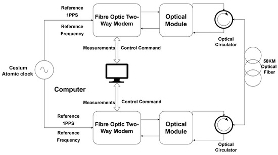
Figure 5.
Experimental setup.
The fiber optic bidirectional time delay measurement equipment used is self-developed equipment which can realize pseudo-random code modulation, pseudo-distance measurement, carrier modulation, carrier phase measurement, and bidirectional comparison function. The cesium atomic clock provides a clock reference source for the bidirectional time delay measurement module. The pseudo-code rate of the output signal is 10.23 MHz, and different code types are used at the two sites. The carrier frequency is 1268.52 MHz, and the device is connected to a computer through the network port to transmit the measured data and control command data.
The optical transceiver module can realize light intensity modulation and photoelectric detection; the optical output wavelength of the optical transceiver module of the two sites are 1560.60 nm and 1560.42 nm; the optical output power is 10.15 dBm and 10.32 dBm, which can be used for the transmission of 1–3 GHz radio frequency (RF) signals.
The fiber optic link consists of 50 km of single-mode fiber and two optical circulators; the attenuation coefficient of the single-mode fiber is 0.18 dB/km at 1560 nm, and the optical circulators are designed to enable bidirectional transmission of optical signals in the same fiber to ensure the symmetry of the bidirectional transmission time delay.
During the fiber optic bidirectional time transfer experiment, the bidirectional time delay measurement equipment generates a pseudo-random code modulation signal, which is modulated onto the carrier through the RF module to become an RF modulation signal. The continuous wave laser in the optical transmitter module intensity-modulates the RF signal. The RF signal enters the fiber optic link for transmission after passing through the optical circulator, and the photodetector in the optical receiver module debits the received optical signal and recovers the RF modulation signal which is to be sent to the bidirectional time delay measurement equipment. The time delay measurement equipment down-converts the RF signal and then locks the received signal through the capture and tracking loop to obtain the carrier phase measurement value and pseudo-code phase measurement value. The measured pseudo-code phase measurements and carrier phase measurements are fused using Kalman filtering. Based on the measured data, the clock difference measurement value of the clock is solved by two-way comparison. The computer collects the measured data by means of network port communication, and the two ends of the fiber optic bidirectional time transfer have a completely symmetrical structure.
5. Discussion
Because of the hardware delay of the fiber optic bidirectional modem equipment as well as the optical module, it is necessary to calibrate the hardware delay using the same clock using the zero-baseline experiment before conducting the experiment, and the calibrated delay result in the experiment of this paper is 0.728 ns, and the result of the clock difference comparison is near the zero value after the calibration. The time reference at both ends of the system is derived from the same cesium clock, so the settlement result of the clock difference represents the time transfer performance of the system. The clock difference can be solved directly by bidirectional comparison of the pseudo-code phase measurements obtained through the two sites, but due to the existence of the integer ambiguity, the carrier phase measurements obtained have higher precision and cannot be used directly for the calculation of clock difference after bidirectional comparison. Therefore, a high-precision clock difference measurement is achieved by fusing the carrier phase measurement after comparison through first-order differencing with the clock difference obtained from the pseudo-code phase measurement through Kalman filtering. We smoothed the measured data for 10 s finally. The clock difference measured directly by the pseudo-code phase measurement and the clock difference measured after Kalman fusion are shown in the Figure 6. The peak-to-peak value of the clock difference obtained from the pseudo-code phase measurement is 71 ps, and the standard deviation is 8.346 ps, while the peak-to-peak value of the clock difference converged by the Kalman filter is 13 ps, and the standard deviation is 2.4255 ps, which is a big improvement in precision.
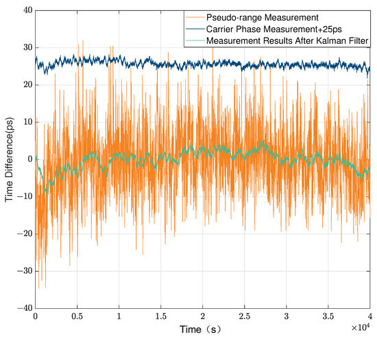
Figure 6.
Common clock time difference measurement in 50 km fiber.
In the field of fiber optical time transfer, the stability of clock signal measurements after transmission is usually evaluated using the modified Allan deviation and time deviation. The Allan deviations are shown in Figure 7a. The modified Allan deviations of the pseudo-code ranging-based time difference measurements are /s, / s and / s. After the Kalman filter fusion, the modified Allan deviations are /s, / s and / s, which is an order of magnitude improvement in the short-term stability. The time deviation of the common clock experimental platform is shown in Figure 7b. The time deviation of the pseudo-code ranging-based time difference measurements are /s, / s and / s. The time deviations after Kalman filtering are /s, / s and / s.
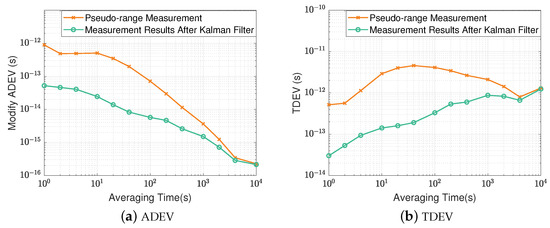
Figure 7.
Stability analysis of common clock time difference measurements.
As shown in Figure 7, the short-term stability of the time transfer system after filter fusion is significantly improved due to the introduction of a higher-precision carrier phase measurement to smooth the measured clock difference, suppress the noise of the pseudo-code phase measurement, and improve the precision of the clock difference measurement, thus improving the short-term stability of the time synchronization system. The long-term stability of the system converges. This is due to the fact that the long-term stability of the system is related to the stability of the fiber optic link and the optical module, and improving the precision of the clock delay measurement has a limited effect on it.
6. Conclusions
In recent years, with the increasing demand for high-precision time and frequency in various fields, time and frequency transfer technology has developed rapidly. In particular, fiber optic time and frequency transfer, due to its high precision, anti-interference ability, and wide coverage, has become the first choice of high-precision time and frequency solutions, and fiber optic time and frequency transfer in the field of time and frequency transfer. The development of the frequency transfer is faster than the time transfer, and it is able to achieve transmission with a stability of the order of magnitude of , but the fiber optic time and frequency transfer is limited by the time delay measurement precision of the pulse signals, and cannot profit from the higher precision of the carrier phase information and its performance compared to the frequency transfer. There is a large gap in the transmission of the frequency transfer. Therefore, in the field of fiber optic time transfer, this paper proposes a high-precision fiber optic transfer time delay measurement method based on Kalman filtering.
Different from the traditional time transfer method, this paper achieves a high-precision and blur-free time delay measurement by applying pseudo-code phase measurement and carrier phase measurement to the time delay measurement of the fiber optic time transfer system. Compared with the 1PPS fiber optic time transfer system, there is no need to use different optical wavelengths to suppress backward scattering, and therefore, no need for a complex time delay compensation system. The transmission precision is also improved. Compared with a fiber optic time transfer system that directly uses pseudo-random codes, the introduction of carrier phase measurements for filter fusion improves the precision and short-term stability of the time transfer system. M Rost et al. [20] achieved time transfer through optical fibers over a distance of 73 km with an uncertainty below 100 ps by directly using pseudo-random codes, compared with the fiber optic time transfer system over a 50 km fiber optic link which achieved a peak-to-peak value of 13 ps, a standard deviation of 2.4255 ps, and a short-term stability of /s (time deviation) in this article; the precision has been significantly improved by using the theory in this paper.
The method proposed in this paper can be used in the construction of fiber optic time transfer systems and has a large networking potential. By assigning pseudo-random codes with different addresses to each site, the same wavelength transmission can be used in the optical transmission network, which greatly simplifies the structure of the networked fiber optic time transfer system. It can achieve high transmission precision and have good stability, and can meet the demand of high-precision time transfer or time comparison. The carrier phase measurement method is introduced in the fiber optic time transfer system, which lays the foundation for the research of high-precision time transfer technology.
Author Contributions
Conceptualization, H.S.; methodology, H.S. and H.G.; software, H.S. and J.P.; validation, H.S.; formal analysis, H.S. and J.P.; investigation, H.S.; resources, H.S. and J.P.; data curation, H.S.; writing—original draft preparation, H.S.; writing—review and editing, H.S.; visualization, H.G.; supervision, H.G.; project administration, H.G.; funding acquisition, H.G. All authors have read and agreed to the published version of the manuscript.
Funding
This research was funded by the National Natural Science Foundation of China (U20A0193) and Hunan Provincial Science and Technology Innovation Plan (2021RC3073).
Institutional Review Board Statement
Not applicable.
Informed Consent Statement
Not applicable.
Data Availability Statement
Data may be obtained from the authors upon request.
Conflicts of Interest
The authors declare no conflict of interest.
References
- Nicholson, T.L.; Campbell, S.; Hutson, R.; Marti, G.E.; Bloom, B.; McNally, R.L.; Zhang, W.; Barrett, M.; Safronova, M.S.; Strouse, G.; et al. Systematic evaluation of an atomic clock at 2×10⁻¹⁸ total uncertainty. Nat. Commun. 2015, 6, 6896. [Google Scholar]
- Borio, D.; Camoriano, L.; Savasta, S.; Presti, L.L. Time-frequency excision for GNSS applications. IEEE Syst. J. 2008, 2, 27–37. [Google Scholar]
- Tavella, P.; Petit, G. Precise time scales and navigation systems: Mutual benefits of timekeeping and positioning. Satell. Navig. 2020, 1, 12. [Google Scholar]
- Ge, Y.; Wang, Q.; Wang, Y.; Lyu, D.; Cao, X.; Shen, F.; Meng, X. A new receiver clock model to enhance BDS-3 real-time PPP time transfer with the PPP-B2b service. Satell. Navig. 2023, 4, 8. [Google Scholar]
- Gao, Q.; Zhou, M.; Han, C.; Li, S.; Zhang, S.; Yao, Y.; Li, B.; Qiao, H.; Ai, D.; Lou, G.; et al. Systematic evaluation of a 171Yb optical clock by synchronous comparison between two lattice systems. Sci. Rep. 2018, 8, 8022. [Google Scholar]
- Lau, K.Y.; Lutes, G.F.; Tjoelker, R.L. Ultra-stable RF-over-fiber transport in NASA antennas, phased arrays and radars. J. Light. Technol. 2014, 32, 3440–3451. [Google Scholar]
- Liu, L.; Tang, G.; Han, C.; Shi, X.; Guo, R.; Zhu, L. The method and experiment analysis of two-way common-view satellite time transfer for compass system. Sci.-China-Phys. Mech. Astron. 2015, 58, 89502. [Google Scholar]
- Jiang, Z.; Zhang, V.; Parker, T.E.; Petit, G.; Huang, Y.J.; Piester, D.; Achkar, J. Improving two-way satellite time and frequency transfer with redundant links for UTC generation. Metrologia 2019, 56, 025005. [Google Scholar]
- Cheng, P.; Shen, W.; Sun, X.; Cai, C.; Wu, K.; Shen, Z. Measuring Height Difference Using Two-Way Satellite Time and Frequency Transfer. Remote Sens. 2022, 14, 451. [Google Scholar]
- Haoyuan, L.; Zhaolong, L.; Jiaxin, W.; Hongling, M.; Jianye, Z. Two-Way Optical Time and Frequency Transfer Over a 20-km Fiber Link Based on Optical Frequency Combs. IEEE Photonics J. 2019, 11, 1–7. [Google Scholar]
- Wang, L.; Liu, Y.; Jiao, W.; Hu, L.; Chen, J.; Wu, G. Fast and on-line link optimization for the long-distance two-way fiber-optic time and frequency transfer. Opt. Express 2022, 30, 25522–25535. [Google Scholar] [PubMed]
- Zuo, F.; Xie, K.; Hu, L.; Chen, J.; Wu, G. 13 134-Km Fiber-Optic Time Synchronization. J. Light. Technol. 2021, 39, 6373–6380. [Google Scholar]
- Feifei, Y.; Zhongle, W.; Yitang, D.; Tianpeng, R.; Kun, X.; Jintong, L.; Geshi, T. Stable fiber-optic time transfer by active radio frequency phase locking. Opt. Lett. 2014, 39, 3054–3057. [Google Scholar]
- Lu, Z.; Gui, Y.; Wang, J.; Ying, K.; Sun, Y.; Liu, L.; Cheng, N.; Cai, H. Fiber-optic time-frequency transfer in gigabit ethernet networks over urban fiber links. Opt. Express 2021, 29, 11693–11701. [Google Scholar] [PubMed]
- Fordell, T. Open-loop polarization mode dispersion mitigation for fibre-optic time and frequency transfer. Opt. Express 2022, 30, 6311–6319. [Google Scholar] [CrossRef]
- Yang, H.; Han, B.; Shin, J.; Hou, D.; Chung, H.; Baek, I.H.; Jeong, Y.U.; Kim, J. 10-fs-level synchronization of photocathode laser with RF-oscillator for ultrafast electron and X-ray sources. Sci. Rep. 2017, 7, 39966. [Google Scholar] [PubMed]
- Huang, W.; Li, Y.; Zhang, P.; Fang, L.; Hou, D. Femtosecond-Level Frequency Transfer at 10 GHz over Long Fiber Link with Optical–Electronic Joint Compensation. Appl. Sci. 2022, 12, 1262. [Google Scholar] [CrossRef]
- Dierikx, E.F.; Wallin, A.E.; Fordell, T.; Myyry, J.; Koponen, P.; Merimaa, M.; Pinkert, T.J.; Koelemeij, J.C.; Peek, H.Z.; Smets, R. White rabbit precision time protocol on long-distance fiber links. IEEE Trans. Ultrason. Ferroelectr. Freq. Control 2016, 63, 945–952. [Google Scholar]
- Liu, B.; Guo, X.; Kong, W.; Liu, T.; Dong, R.; Zhang, S. Stabilized Time Transfer via a 1000-km Optical Fiber Link Using High-Precision Delay Compensation System. Photonics 2022, 9, 522. [Google Scholar]
- Rost, M.; Piester, D.; Yang, W.; Feldmann, T.; Wübbena, T.; Bauch, A. Time transfer through optical fibres over a distance of 73 km with an uncertainty below 100 ps. Metrologia 2012, 49, 772. [Google Scholar]
- Śliwczyński, Ł.; Krehlik, P.; Lipiński, M. Optical fibers in time and frequency transfer. Meas. Sci. Technol. 2010, 21, 075302. [Google Scholar]
- Chen, Z.; Zuo, F.; Hu, L.; Jin, Y.; Chen, J.; Wu, G. Time Synchronization System Based on Bidirectional Time-Division Multiplexing Transmission over Single Fiber with Same Wavelength. Chin. J. Lasers 2021, 48, 159–164. [Google Scholar]
- Fujieda, M.; Piester, D.; Gotoh, T.; Becker, J.; Aida, M.; Bauch, A. Carrier-phase Two-Way Satellite Frequency Transfer over a Very Long Baseline. Metrologia 2014, 51, 253. [Google Scholar]
- Wang, S.; Zhao, X.; Ge, Y.; Yang, X. Investigation of real-time carrier phase time transfer using current multi-constellations. Measurement 2020, 166, 108237. [Google Scholar]
- Parker, T.E.; Zhang, V.; Petit, G.; Yao, J.; Brown, R.C.; Hanssen, J.L. A three-cornered hat analysis of instabilities in two-way and GPS carrier phase time transfer systems. Metrologia 2022, 59, 035007. [Google Scholar]
- Betz, J.W.; Kolodziejski, K.R. Extended Theory of Early-Late Code Tracking for a Bandlimited GPS Receiver. Navigation 2000, 47, 211–226. [Google Scholar] [CrossRef]
Disclaimer/Publisher’s Note: The statements, opinions and data contained in all publications are solely those of the individual author(s) and contributor(s) and not of MDPI and/or the editor(s). MDPI and/or the editor(s) disclaim responsibility for any injury to people or property resulting from any ideas, methods, instructions or products referred to in the content. |
© 2023 by the authors. Licensee MDPI, Basel, Switzerland. This article is an open access article distributed under the terms and conditions of the Creative Commons Attribution (CC BY) license (https://creativecommons.org/licenses/by/4.0/).