Article

Flexible Terahertz Metamaterials Absorber based on VO2

1
School of Mechanical Engineering, Chengdu University, Chengdu 610106, China
2
College of Materials Science and Engineering, Sichuan University, Chengdu 610065, China
*
Authors to whom correspondence should be addressed.
Photonics 2023, 10(6), 621; https://doi.org/10.3390/photonics10060621
Submission received: 29 April 2023 / Revised: 22 May 2023 / Accepted: 25 May 2023 / Published: 28 May 2023
(This article belongs to the Special Issue Light Control and Particle Manipulation)

Abstract

:
Terahertz (THz) metamaterials have attracted great attention due to their widely application potential in smart THz devices; however, most of them are fabricated on rigid substrate and thus limit the exploration of flexible THz electronics. In this paper, a flexible THz metamaterial absorber (MMA) incorporated with phase change material vanadium dioxide (VO2) is proposed. The simulation results indicate that two absorption peaks at around 0.24 THz (marked as A) and 0.46 THz (marked as B) can be observed by designing a I-shaped metamaterial combined with split ring structure. The strong absorption over 92% at 0.24 THz is bending-insensitive, but the absorption at 0.46 THz is bending-sensitive, across the bending angle in the range of 0–50 degrees. Moreover, dynamic modulation of the absorption can be achieved across the insulator-metal phase transition of VO2. Particularly, the absorption of the A-peak can be tuned from 99.4% to 46.9%, while the absorption of the B-peak can be tuned from 39.6% to 99.3%. This work would provide significance for the design of flexible THz smart devices.

1. Introduction

Terahertz (THz) wave are located between 0.1–10 THz range and has been widely investigated due to its great application potential in next-generation communication, imaging technology [1], space remote sensing [2], non-destructive testing [3], etc. Particularly, the development of THz technology strongly leads to the development of THz wave manipulation devices, including switches [4], modulators [5], filters [6], absorbers [7], and polarizers [8], etc.; however, the weak response between THz waves and natural materials severely limits their development. Fortunately, metamaterials composed of subwavelength unit structures with supernatural properties that conventional materials do not possess provide a new way to solve the problem [9].
THz MMAs can efficiently absorb electromagnetic waves due to the tunable electromagnetic properties of artificially designed unit structures. Although the MMAs reported can achieve high absorptivity, most of them still have many drawbacks, such as single wave band, narrow receiving angle, fixed resonant frequency and absorption intensity, which greatly limit their practical applications [10,11,12,13,14]. Additionally, most of the MMAs can only achieve static electromagnetic absorption; once the processing is completed, their absorbing performance will be fixed. To address this issue, tunable dielectric materials are incorporated into the structure of the MMA to achieve dynamic manipulation of THz waves [15,16,17,18]. For example, Liu et al. propose a broadband-tunable THz absorber based on VO2. This absorber can achieve a maximum tunable range of 5% to 100% by external thermal excitation, and it achieves more than 80% absorption in the 2.0 THz bandwidth [19]. Mou et al. propose a flexible, thermally convertible THz metasurface, whose structure can achieve ultra-broadband absorption from 0.398 THz to 1.356 THz when the ambient temperature reaches 358 K. Additionally, it achieves more than 90% absorption with a relative absorption bandwidth of 109.2% [20].
VO2 is a thermally induced phase transition metal oxide that undergoes a reversible transformation from a low-temperature insulating phase to a high-temperature metallic phase near 340 K, accompanied by reversible changes in its optical, electrical, and magnetic properties [21]. Therefore, by inducing the phase transition of VO2 through temperature modulation and altering its conductivity, dynamic control of THz waves can be achieved. In addition, the reports on phase-change-material-integrated THz components are mostly limited to rigid substrates, which cannot meet the flexible and lightweight requirements of some application scenarios. Flexible metamaterials offer the potential to be flexible, stretchable and reversible, which helps to manipulate electromagnetic waves according to specific requirements. Flexible metamaterials can therefore be used for curved surfaces in a range of devices or installations, which makes them promising for a wide range of innovative applications, including mobile and wearable devices [22], stealth [23], smart skin [24], etc. Additionally, by integrating metamaterials onto flexible substrates, flexible metamaterials can be realized. For example, Wang et al. created a stretchable, microwave-invisible photonic skin made of rigid scales using pangolin-inspired metamaterial design [25]. A flexible spiraling elastic metasurface has been used to build a generic haptic interface, which is capable of distinguishing various tactile sensations by locally amplifying both incoming displacements and forces in a wide range of elastic waves [26]. Such compelling achievements provide superb boilerplates for flexible THz MMAs. Xiao et al. propose a flexible and ultra-wideband THz wave absorber that keeps an average power absorptance over 98.9% from 0.1 to 2.5 THz and that can function well in bended states and after 300 times bending cycles [27]. This MMA is expected to be applied to wearable devices, wireless communications and biological sensing due to the flexibility, high-absorptance performance and ultra-wideband operation of the device. Nowadays, how to fabricate flexible and tunable THz MMAs with a uniformly high absorptance across the entire THz band merely based on traditional bulk materials is still a challenging but meaningful task.
In this paper, we proposed a flexible VO2-based THz-tunable MMA. The I-shaped metamaterial combined with split ring structure achieves nearly perfect absorption at 0.24 THz and another absorption at 0.46 THz at normal incidence. The absorber is bending-insensitive at 0.24 THz and bending-sensitive at 0.46 THz before the phase transition of VO2. Moreover, the tunable absorption can be achieved by triggering the phase transition of VO2. This work would provide significant insights for the development of flexible THz smart devices.

2. Materials and Methods

The microstructure of the proposed metamaterial array is shown in Figure 1. The absorber continues the basic metal–dielectric-metal structure. The top and bottom metal layers are both gold, and the thickness is 0.3 μm and 2 μm, respectively. The main function of the bottom metal plate is to prevent THz wave transmission through the sample. The middle layer is mica with a dielectric constant of 6.7 and a thickness of 40 μm. The top layer is a periodic gold unit array incorporated with VO2. The unit is composed of an I-shaped resonator and split ring. The VO2 is embedded in both sides where the split ring meets the metal bar.
To confirm transmission variations, the designed MMA structure in Figure 1 was simulated by finite element simulation using the commercial software CST Microwave Studio. In the calculation, the x-direction and the y-direction is the unit cell condition, and the z-direction is open (add space) using. THz waves are incident on the absorber along the angle between the plane of incidence and the z-axis, and the electric field of the incident wave is polarized along the y direction, and the magnetic field is polarized along the x direction. Two metallic layers of this MMA were modeled as lossy metal gold with a frequency-independent conductivity (r) of 4.56 × 10⁷ S/m. We calculate the THz reflectivity (R), transmissivity (T), and absorptivity (A) in detail. The absorptivity A can be calculated by the equation A = 1 − R − T = 1 − |S11|2 − |S21|2, where S11 and S21 are reflection coefficients and transmission coefficients, respectively. At this time, the thickness of the metal film is far greater than the skin depth of the incident electromagnetic wave, and the metal film used can completely prevent the transmission of the incident beam. In addition, by selecting an appropriate dielectric layer thickness to match the impedance of the metamaterial with that of the air, the absorbance A can be simplified as A = 1 − |S11|2. When S11 is very small, even close to zero, A becomes infinitely close to 1.

3. Results and Discussion

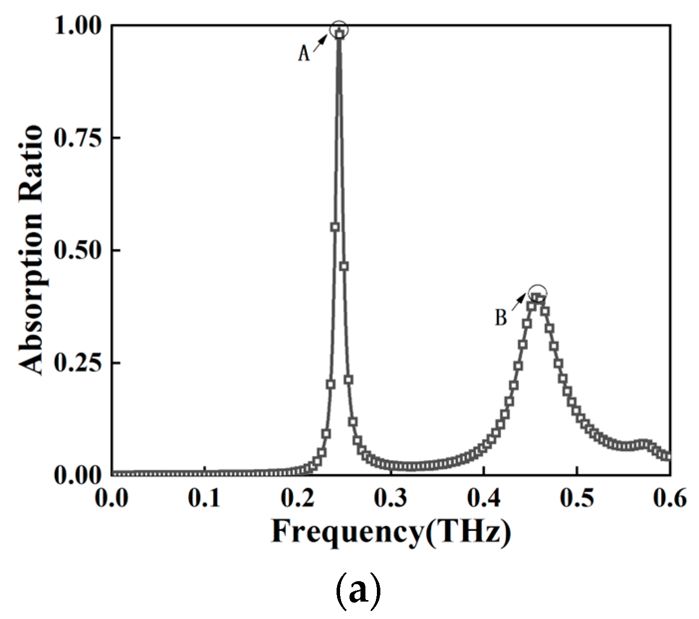
Figure 2a illustrates the absorption curves of the proposed MMA at optimal structural parameters and normal incidence. At a temperature of about 323 K, below the phase transition temperature, VO2 can be considered an insulator with a conductivity of 10 S/m. The simulation results show that on a normal incidence of 0 degrees, the designed MMA can produce two resonant peaks (marked as A and B) with frequencies of 0.24 THz and 0.46 THz and absorptivity of 99.4% and 39.6%, respectively.
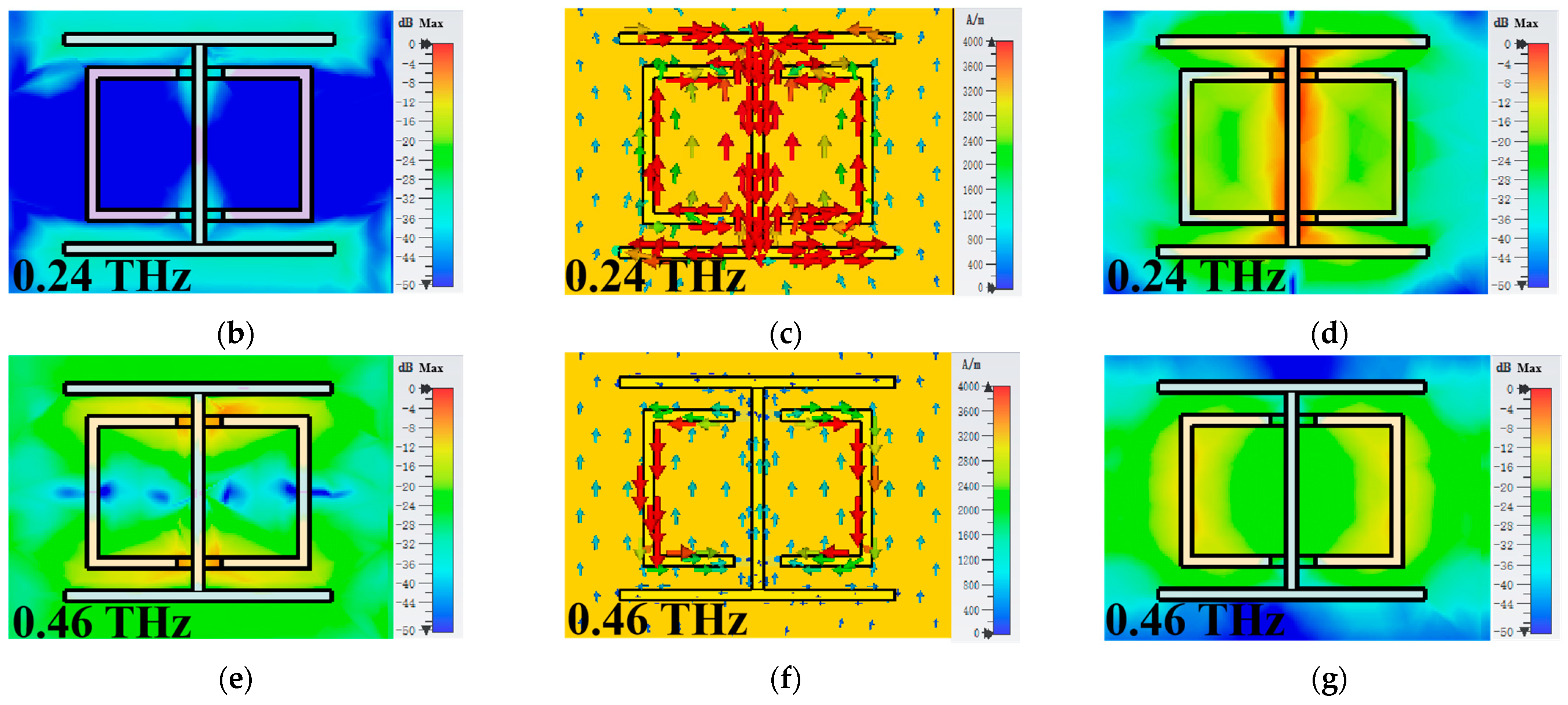
To understand the absorption mechanism of this absorber, we calculate the electric field distribution, surface current density and magnetic field distribution of absorption peaks A and B; the results are shown in Figure 2b–g. For the resonance peak A at 0.24 THz, the electric field distribution is weak, while the current on the vertical metal bar is opposite to the current on the bottom metal plate. The I-shaped metallic resonators can be modeled as a LC circuit, in which the capacitance (C) result from the electric field distribution in the gaps between the adjacent periodic I-shaped metallic resonators, and the inductance (L) is related to the current distribution in the metallic wires, and leads to a strong LC resonance. In addition, the magnetic field distribution in Figure 2d also provides further evidence. The magnetic field is mainly concentrated on the vertical metal rod. Strong magnetic field aggregation can also be found in the insulating medium layer under the metal arrays and non-metal array. Different from the field distribution characteristics of resonance peak A, the electric field distribution of peak B focuses on the gap of the split ring. The magnetic field is mainly distributed in the metal area of the split ring, and strong magnetic field accumulation can be found in the insulating dielectric layer under the metal array.
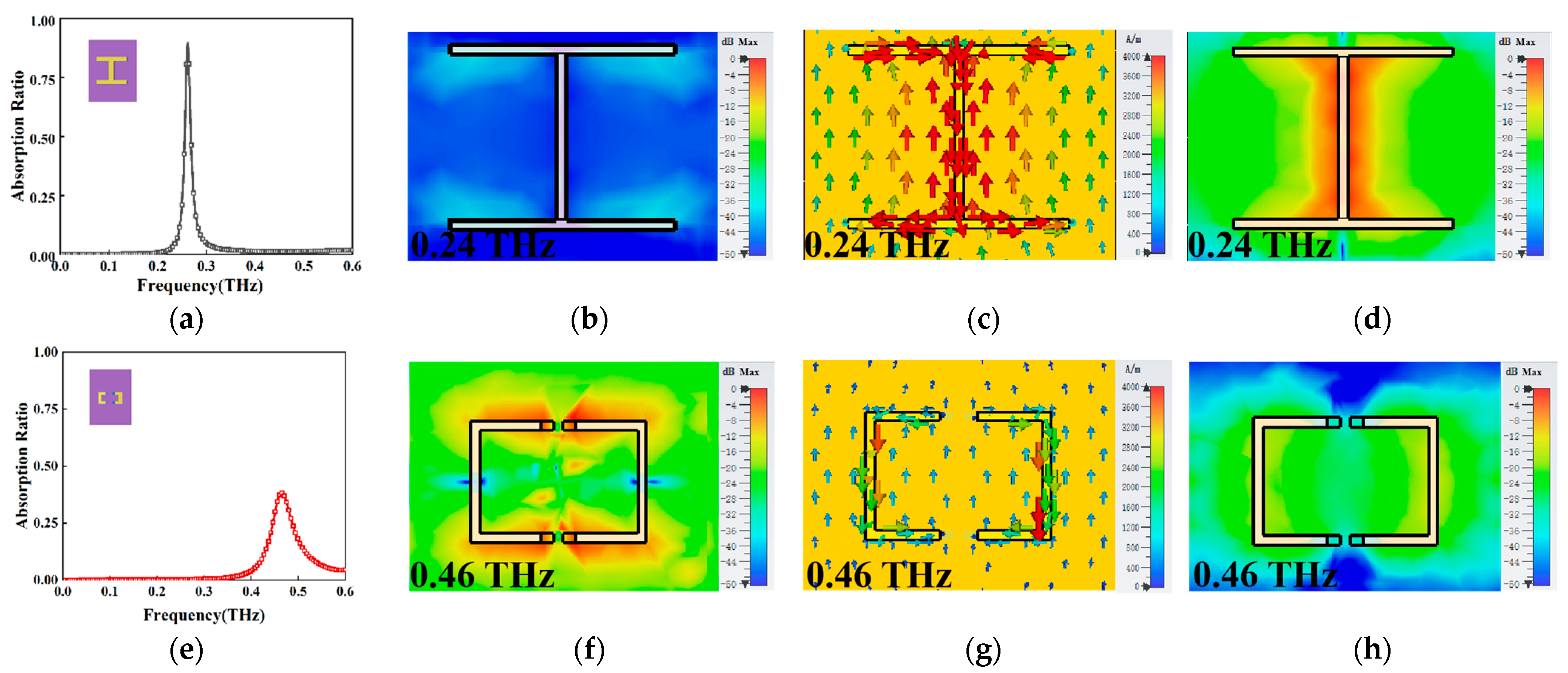
To better interpret the formation mechanism of absorption peaks, we decompose the unit structure into an I-shaped structure and split ring structure, and analyze their electromagnetic characteristic in detail. As shown in Figure 3a, the I-shaped structure induces a resonant peak with an amplitude of 0.90 at 0.26 THz. It can be ascribed to the LC resonance [28] according to:
f = 1 2 π L C
where f decreases when L or C increases. To better explain the mechanism of the resonance curve, we simulate the distribution of the electric field, surface-current density, and magnetic field of the I-shaped structure at the formant. The surface-current density distribution at 0.26 THz in Figure 3c shows that the current flow on the vertical metal rod is in the opposite direction to the current flow on the metal base plate. Since no loop will be formed, resonance will eventually occur, which can also prove the LC resonant characteristics of this structure. It can be seen from Figure 3d that the strong magnetic field is mainly concentrated on the metal vertical pole. Figure 3e is the absorption spectrum of the THz waves normal incidence to the split ring. It can be seen that there is an absorption peak at 0.46 THz with an absorptivity of 38.25%. At this time, VO2 is insulating, the magnetic field concentrates mainly on the sides of the split ring and generates a large amount of current in the opposite direction to the base. There is almost the same peak intensity and position for both resonant frequency structures as for the whole structure in Figure 2a, providing evidence that the two absorption peaks from the MMA are independently contributed by the I-shaped and split ring. For the peak positions, the small difference is due to the loading effect when the two resonators are combined. This means that each absorption peak responds to the contribution of a different sub-element that constitutes the unit cell of the MMA structure. Thus, the overall absorption spectrum appears as a superposition of the contributions of each sub-element [29].
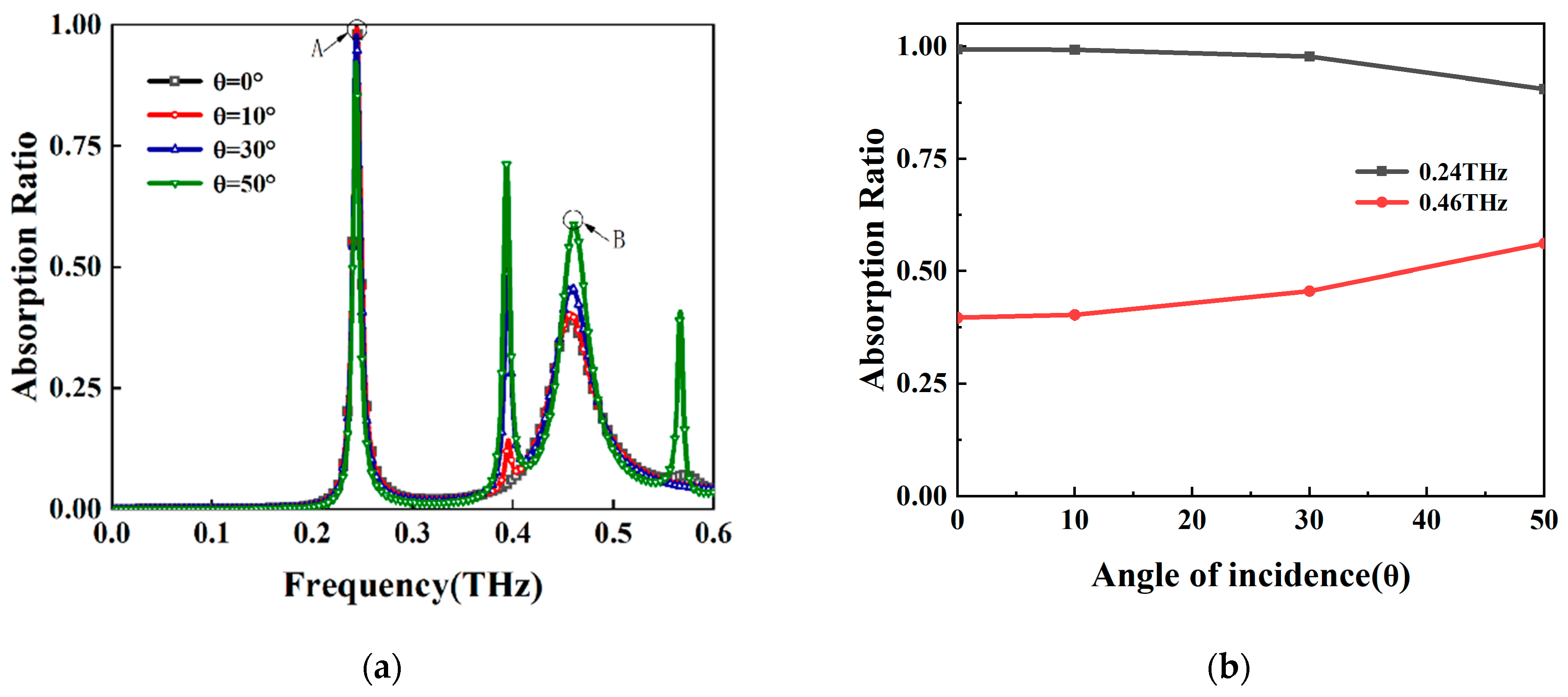
Most traditional THz absorbers use inflexible metamaterials, which limits their application prospects. Since the overall thickness of the proposed structure is only 42.3 μm, it can be flexibly bent and easily to conform to the curved target. For cylindrical objects covered with absorbing material, when the plane electromagnetic wave irradiates to the surface of the object, it can be equated to the oblique incidence of the electromagnetic wave at different angles [30]. Thus, we use the incidence angle to simulate its bending state. Next, we will analyze the effects of different incidence angles on the performance of the designed MMA. Additionally, the results are shown in Figure 4a, where Figure 4b is the dot plot of the variation in absorptivity at different incident angles for 0.24 THz and 0.46 THz. It can be seen from Figure 4a that peak A still has near-perfect absorptivity (more than 92%) after scanning at 0–50 degrees. When the peak resonance frequency is 0.24 THz, the absorption line width is 0.01 THz. It should be noted that the so-called absorption line width refers to the full width of the maximum half width. In this case, it refers to the span with absorption of 50%. To understand the device performance further, we have calculated the quality factor for the resonance modes. The quality factor is typically defined as
Q = f r e s F W H M
of which fres is the resonance frequency of the absorption peak. We can calculate that the Q value at 0.39 THz is 51.03 at an oblique incidence of 30 degrees, but 48.81 at an oblique incidence of 50 degrees, which means that the Q-factor of the resonant mode near 0.39 THz decreases as the angle of oblique incidence increases. This phenomenon can be attributed to the physics of bound states in the continuum (BICs). BICs are waves that remain localized even though they coexist with a continuous spectrum of radiating waves that can carry energy away [31]. Among the many causes of metamaterial BICs in metamaterials, coupled mode theory (CMT) is a flourishing and widespread theory that is widely used in many systems [32,33,34,35]. Here, BICs and quasi-BICs come from metamaterial structures with I-shaped and split ring coupling.
Additionally, the numerical simulation results show that two resonance peaks are generated at 0 degrees of incidence with frequencies of 0.24 THz and 0.46 THz, respectively, and that four resonance peaks are generated at 50 degrees of incidence with frequencies of 0.24 THz, 0.4 THz, 0.46 THz, and 0.57 THz, with absorption rates of about 92.3%, 71.3%, 58.8%, and 33.3%, respectively. As the angle of incidence increases, the A peak ends up red shifted by 0.6 GHz and the B peak ends up blue shifted by 3.7 GHz, but their frequency points remain roughly unchanged. Additionally, as shown in Figure 4b, the amplitudes of the A and B peaks decrease with the increase in the angle, with the A peak changing by 0.07, but the amplitude intensity of the B peak changing significantly by 0.19. Therefore, it can be considered that peak A is bending-insensitive and peak B is bending-sensitive.
The electric field distributions of the proposed MMA at different incidence angles of 0.24 THz and 0.46 THz are given in Figure 5. From Figure 5a–d, it can be seen that as a symmetric structure, the electric field at 0.24 THz also remains symmetric, the electric field intensity gradually increases, and the position remains constant when the incidence angle increases. Additionally, from Figure 5e–h, it can be seen that the electric field at 0.46 THz is not symmetric; the electric field intensity gradually decreases; and scattered distribution, when the incidence angle increases, and the absorption characteristics are affected by it. Therefore, from the combined absorption spectrum shown in Figure 4, it can be considered that peak A is bending-insensitive and peak B is bending-sensitive.
The electric field distribution, surface current density, and magnetic field distribution of the four peaks at 50 degrees oblique incidence are given in Figure 6a–l, and their formation mechanisms are revealed. For the resonance peak A at 0.24 THz, the distribution of the electric field and magnetic field is roughly similar to peak A at normal incidence. The distribution of electric field is strengthened and evenly distributed on the two transverse bars of the I-shaped structure. The current is mainly distributed on the metal structure, and the current on the vertical metal bar is opposite to the current on the bottom metal plate and produces LC resonance. The magnetic field is mainly concentrated on the vertical metal bar, but it is weaker than at normal incidence. The electric and magnetic fields at 0.39 THz are mainly concentrated on the left side of the split ring, so there is also a small current on the left side of the split ring and the I-shaped resonator. When the electric field of resonance peak B in Figure 6 is weakened, a strong magnetic field appears on the split ring and a large current gathers; the magnetic response is enhanced. For the resonant peak at 0.57 THz, the distribution of the magnetic field is the opposite of the peak at 0.39 THz. It is concentrated just to the right of the split ring, and the current is also concentrated to the right of the split ring and on the I-shaped resonator.
In practical applications, efficient and flexible absorbers not only need to absorb as much radiation as possible but also need to achieve tunable functionality. Therefore, we also evaluate the performance of the absorber during the phase transition at different incident angles, and the results as shown in Figure 7, where (b) and (c) are plots of absorptivity variation with the conductivity of VO2 for different incident angles at 0.24 THz and 0.46 THz, respectively. When the THz wave is normally incident on the MMA, a blue shift of 4.8 GHz occurs in the A-peak with a peak drop from 99.4% to 46.9% after the complete phase transition of VO2, while for the B-peak, a red shift of 0.48 GHz occurs with a peak increase from 39.6% to 99.3%. When the conductivity is 1000 S/m, the frequency points of the absorption peaks remain unchanged, but most of its resonance peak intensities decrease. For peak A, the absorptivity decreases from 92.6% to 79.5% when the incident angle increases from 0 to 50 degrees, with a red shift of 0.6 GHz at the frequency point of 0.24 THz. For peak B, the absorptivity rises from 61% to 81.3% when the incident angle increases from 0 to 50 degrees, with a blue shift of 4.1 GHz at the frequency point of 0.46 THz. It can be seen from Figure 6a that when the conductivity reaches 10,000 S/m, there are only two peaks with frequencies of 0.25 THz and 0.46 THz, respectively. The absorptivity decreases from 46.9% to 34% when the incident angle increases from 0 to 50 degrees, with a red shift of 0.6 GHz at the frequency point of 0.25 THz; however, the second peak B is stronger, and the absorptivity decreases from 99.3% to 89.3% when the incident angle increases from 0 to 50 degrees, with a blue shift of 4.4 GHz at the frequency point of 0.46 THz.
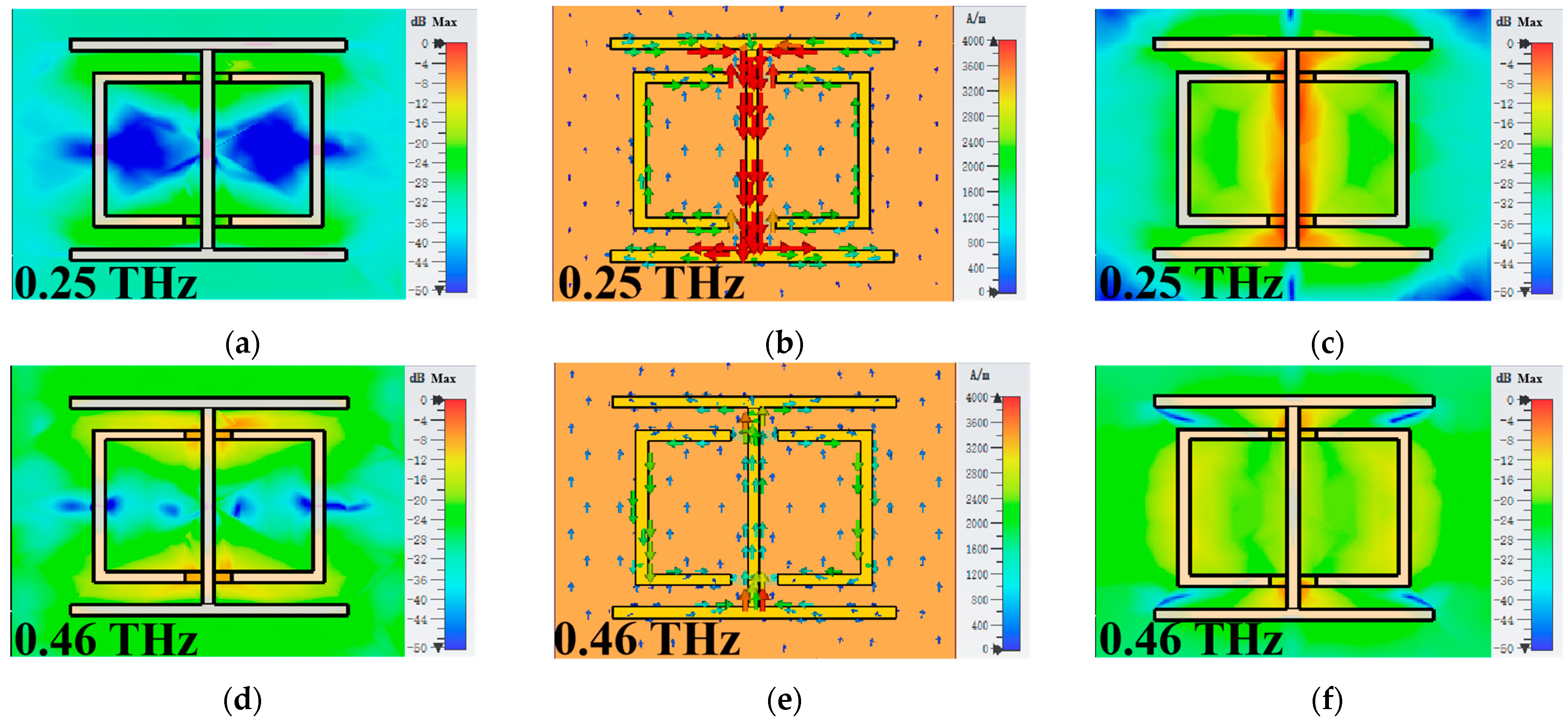
Figure 8 shows the electric field distribution, surface current density and magnetic field distribution at 0.24 THz and 0.46 THz with the conductivity of 1000 S/m. The electric field and surface current density are unchanged, but the magnetic field strength has weakened. The same is true for the electric field and surface current density of peak B, and the magnetic field strength on the split ring is slightly strengthened, so the absorption peak increases by about 0.22. Meanwhile, there is a transition from insulator phase to metallic phase in VO2, and some molecular particles inside it will first undergo phase change; as the temperature increases further, the number of molecular particles of phase change will gradually increase, and metallic structure will appear inside VO2 material. The absorption spectra have a clear change, which is easy to be understood and has been discussed in many reported literature [36]. Additionally, since the phase change material VO2 is used, we can modulate this absorber by triggering the phase transition of VO2 incorporated in the metamaterials. To quantify the modulation efficiency, we extract the modulation depth as [37]
M D = T ( f ) m a x T ( f ) m i n / T ( f ) m a x
where M D denotes the modulation depth at frequency f , T ( f ) m a x and T ( f ) m i n denote the transmission coefficients at frequency f , the maximum and minimum values, respectively. At this point, the modulation depth at 0.24 THz is 6.88%, while the modulation depth at 0.46 THz is higher, at 35.12%.
When the conductivity reaches 10,000 S/m, VO2 achieves a phase transition, and significant change in the absorption spectrum occur. The higher the carrier concentration, the smaller the real part of the dielectric constant, and the larger the imaginary part, the more metallic and stronger the ion resonance intensity. The change of the resonance arises from the significant decrease in the real part of the permittivity of VO2 when it transforms to its metallic state. As can be seen from Figure 9a–c, for the absorption peak A, a stronger electric field than at a conductivity of 1000 S/m gathers in VO2. The magnetic field starts to weaken, and the current appears only in the vertical metal rods, which means that the LC resonance of the I-shaped structure is weakening; however, the second peak is strengthening, as can be seen in Figure 9d–f. At this point, the electric field and magnetic field are mainly concentrated in the open loop body and VO2. This is because VO2 has completed the phase transition from the insulating state to the metallic state. The magnetic field distribution at 0.46 THz shows a strong coupling between the I-shaped structure and the split ring (Figure 9f). This is the coupling between the metallic state formed by the VO2 after completing the phase transition and the metal rod between them. Thus this coupling and the dipole resonance on the split ring together enhance the absorption amplitude of the B peak. Now, the modulation depth at 0.24 THz has improved significantly, reaching 52.93%, while the modulation depth at 0.46 THz is higher, at 60.12%. This is mainly due to the stronger electromagnetic response of the THz MMA to THz waves at this time.
Table 1 gives a comparison of our proposed structure with some published works [19,29,38,39,40,41,42], we find that the performance of our proposed structure not only fully combines the advantages of MMAs and flexible materials, but the performance is also much better when compared with existing work and can have many innovative applications in future THz systems, such as electromagnetic cloaking and wearable and implantable applications.

4. Conclusions

To sum up, a flexible and tunable THz MMA is proposed based on VO2. The simulation results indicate that the I-shaped metamaterials combined with split ring structure present two resonant absorption peaks at 0.24 THz and 0.46 THz at normal incidence. By contrast, the absorption at 0.24 THz is nearly insensitive to bending, but the absorption at 0.46 THz is bending-sensitive, across a bending angle of 0–50 degrees. Moreover, the THz absorption amplitude can be tunable by triggering the phase transition of VO2 incorporated in the metamaterials. Particularly, the absorption amplitude at 0.24 THz can be tuned from 99.4% to 46.9%, while the absorption amplitude at 0.46 THz can be tuned from 39.6% to 99.3%. The research results have important research significance for the development of THz flexible devices, which can be applied to perfect intelligent flexible electronic devices application in future studies.

Author Contributions

Conceptualization, Q.S.; Methodology, J.L. (Jin Leng); Software, Z.J. and J.L. (Jin Leng); Validation, Z.J., B.L. and M.Y.; Investigation, Z.J.; resources, X.W.; Data curation, Z.J., J.L. (Jianfei Li) and J.L. (Jin Li); Writing—original draft preparation, Z.J.; Writing—review and editing, Q.S. and J.L. (Jin Leng); Supervision, Q.S. All authors have read and agreed to the published version of the manuscript.

Funding

This research received no external funding.

Institutional Review Board Statement

Not applicable.

Informed Consent Statement

Not applicable.

Data Availability Statement

Not applicable.

Conflicts of Interest

The authors declare no conflict of interest.

References

  1. Hillger, P.; Grzyb, J.; Jain, R.; Pfeiffer, U. Terahertz imaging and sensing applications with silicon-based technologies. IEEE Trans. Terahertz Sci. Technol. 2018, 9, 1–19. [Google Scholar] [CrossRef]
  2. Glück, A.; Rothbart, N.; Schmalz, K. Hübers, H. SiGe BiCMOS Heterodyne receiver frontend for remote sensing with small satellites. IEEE Trans. Terahertz Sci. Technol. 2022, 12, 603–610. [Google Scholar] [CrossRef]
  3. Zhong, S. Progress in terahertz nondestructive testing: A review. Front. Mech. Eng. 2019, 14, 273–281. [Google Scholar] [CrossRef]
  4. Schalch, J.S.; Chi, Y.; He, Y.; Tang, Y.; Zhao, X.; Zhang, X.; Wen, Q.; Averittl, R.D. Broadband electrically tunable VO2-metamaterial terahertz switch with suppressed reflection. Microw. Opt. Technol. Lett. 2020, 62, 2782–2790. [Google Scholar] [CrossRef]
  5. Zhai, Z.H.; Zhu, H.F.; Shi, Q.; Chen, S.C.; Li, J.; Li, Z.R.; Schneider, H.; Zhu, L.G. Enhanced photo responses of an optically driven VO2-based terahertz wave modulator near percolation threshold. Appl. Phys. Lett. 2018, 113, 231104. [Google Scholar] [CrossRef]
  6. Ferraro, A.; Zografopoulos, D.C.; Caputo, R.; Beccherelli, R. Angle-resolved and polarization-dependent investigation of cross-shaped frequency-selective surface terahertz filters. Appl. Phys. Lett. 2017, 110, 141107. [Google Scholar] [CrossRef]
  7. Wu, C.; Fang, Y.; Luo, L.; Guo, K.; Guo, Z. A dynamically tunable and wide-angle terahertz absorber based on graphene-dielectric grating. Mod. Phys. Lett. B 2020, 34, 2050292. [Google Scholar] [CrossRef]
  8. Zubair, A.; Tsentalovich, D.E.; Young, C.C.; Heimbeck, M.S.; Everitt, H.O.; Pasquali, M.; Kono, J. Carbon nanotube fiber terahertz polarizer. Appl. Phys. Lett. 2016, 108, 141107. [Google Scholar] [CrossRef]
  9. Jiang, S.; Liu, X.; Liu, J.; Ye, D.; Duan, Y.; Li, K.; Yin, Z.; Huang, Y. Flexible metamaterial electronics. Adv. Mater. 2022, 34, 2200070. [Google Scholar] [CrossRef]
  10. Hengbo, X. Design, simulation and measurement of a single-band high-transmittance all-dielectric metamaterial filter. Opt. Mater. 2022, 125, 112145. [Google Scholar] [CrossRef]
  11. Liu, S.; Yin, X.; Zhao, H. The tunable single-/narrow-band terahertz metamaterial absorber through photoconductivity. Results Phys. 2022, 39, 105741. [Google Scholar] [CrossRef]
  12. Zhou, Y.; Xia, H.; Zhang, L.; Zhao, Y.; Xie, W. Temperature insensitive ultra-broadband THz metamaterial absorber based on metal square ring resonators. Results Phys. 2021, 22, 103915. [Google Scholar] [CrossRef]
  13. Liang, Y.; Lin, H.; Lin, S.; Wu, J.; Li, W.; Meng, F.; Yang, Y.; Huang, X.; Jia, B.; Kivshar, Y. Hybrid anisotropic plasmonic metasurfaces with multiple resonances of focused light beams. Nano Lett. 2021, 21, 8917–8923. [Google Scholar] [CrossRef]
  14. Stewart, J.W.; Nebabu, T.; Mikkelsen, M.H. Control of Nanoscale Heat Generation with Lithography-Free Metasurface Absorbers. Nano Lett. 2022, 22, 5151–5157. [Google Scholar] [CrossRef]
  15. Zhang, Z.; Xie, Q.; Guo, L.; Su, C.; Wang, M.; Xia, F.; Sun, J.; Li, K.; Feng, H.; Yun, M. Dual-controlled tunable dual-band and ultra-broadband coherent perfect absorber in the THz range. Opt. Express 2022, 30, 30832–30844. [Google Scholar] [CrossRef]
  16. Yao, G.; Ling, F.; Yue, J.; Luo, C.; Ji, J.; Yao, J. Dual-band tunable perfect metamaterial absorber in the THz range. Opt. Express 2016, 24, 1518–1527. [Google Scholar] [CrossRef]
  17. Meng, H.; Shang, X.; Xue, X.; Tang, K.; Xia, S.; Zhai, X.; Liu, Z.; Chen, J.; J, H.; Wang, L. Bidirectional and dynamically tunable THz absorber with Dirac semimetal. Opt. Express 2019, 27, 31062–31074. [Google Scholar] [CrossRef]
  18. Zhang, Y.; Wu, P.; Zhou, Z.; Chen, X.; Yi, Z.; Zhu, J.; Zhang, T.; Jile, H. Study on temperature adjustable terahertz metamaterial absorber based on vanadium dioxide. IEEE Access. 2020, 8, 85154–85161. [Google Scholar] [CrossRef]
  19. Liu, H.; Wang, Z.H.; Li, L.; Fan, Y.X.; Tao, Z.Y. Vanadium dioxide-assisted broadband tunable terahertz metamaterial absorber. Sci. Rep. 2019, 9, 5751. [Google Scholar] [CrossRef]
  20. Mou, N.; Tang, B.; Li, J.; Dong, H.; Zhang, L. Switchable ultra-broadband terahertz wave absorption with VO2-based metasurface. Sci. Rep. 2022, 12, 1–8. [Google Scholar] [CrossRef]
  21. Thompson, Z.J.; Stickel, A.; Jeong, Y.G.; Han, S.; Son, B.H.; Paul, M.J.; Lee, B.; Mousavian, A.; Seo, G.; Kim, H.T.; et al. Terahertz-triggered phase transition and hysteresis narrowing in a nanoantenna patterned vanadium dioxide film. Nano Lett. 2015, 15, 5893–5898. [Google Scholar] [CrossRef] [PubMed]
  22. Suzuki, D.; Oda, S.; Kawano, Y. A flexible and wearable terahertz scanner. Nat. Photonics 2016, 10, 809–813. [Google Scholar] [CrossRef]
  23. Cai, T.; Zheng, B.; Lou, J.; Cai, T.; Zheng, B.; Lou, J.; Shen, L.; Yang, Y.; Tang, S.; Li, E.; et al. Experimental Realization of a Superdispersion-Enabled Ultrabroadband Terahertz Cloak. Adv. Mater. 2022, 34, 2205053. [Google Scholar] [CrossRef] [PubMed]
  24. He, X.; Cui, Y.; Tentzeris, M.M. Tile-based massively scalable MIMO and phased arrays for 5G/B5G-enabled smart skins and reconfigurable intelligent surfaces. Sci. Rep. 2022, 12, 1–10. [Google Scholar] [CrossRef] [PubMed]
  25. Wang, C.; Lv, Z.; Mohan, M.P.; Cui, Z.; Liu, Z.; Jiang, Y.; Li, J.; Wang, C.; Pan, S.; Karim, M.F.; et al. Pangolin-Inspired Stretchable, Microwave-Invisible Metascale. Adv. Mater. 2021, 33, 2102131. [Google Scholar] [CrossRef]
  26. Bilal, O.R.; Costanza, V.; Israr, A.; Palermo, A.; Celli, P.; Lau, F.; Daraio, C. A Flexible Spiraling-Metasurface as a Versatile Haptic Interface. AMT 2020, 5, 2000181. [Google Scholar] [CrossRef]
  27. Xiao, D.; Chen, W.; Sun, L.; Zhu, M.; Ng, Z.K.; Teo, E.H.T.; Zhang, J.; Hu, F. A Flexible and Ultra-Wideband Terahertz Wave Absorber Based on Pyramid-Shaped Carbon Nanotube Array via Femtosecond-Laser Microprocessing and Two-Step Transfer Technique. Adv. Mater. Interfaces 2022, 9, 2102414. [Google Scholar] [CrossRef]
  28. Yu, X.; Gao, X.; Qiao, W.; Wen, L.; Yang, W. Broadband tunable polarization converter realized by graphene-based metamaterial. IEEE Photon. Technol. Lett. 2016, 28, 2399–2402. [Google Scholar] [CrossRef]
  29. Chen, X.; Fan, W. Ultra-flexible polarization-insensitive multiband terahertz metamaterial absorber. Appl. Opt. 2015, 54, 2376–2382. [Google Scholar] [CrossRef]
  30. Yang, P.; Qin, J.; Xu, J.; Tian-Cheng, H. Ultrathin flexible transmission metamaterial absorber. Acta Phys. Sin. 2019, 68, 087802. [Google Scholar] [CrossRef]
  31. Hsu, C.W.; Zhen, B.; Stone, A.D.; Joannopoulos, J.D.; Soljačić, M. Bound states in the continuum. Nat. Rev. Mater. 2016, 1, 1–13. [Google Scholar] [CrossRef]
  32. Huang, W.; Yin, S.; Zhang, W.; Wang, K.; Zhang, Y.; Han, J. Robust and broadband integrated terahertz coupler conducted with adiabatic following. New J. Phys. 2019, 21, 113004. [Google Scholar] [CrossRef]
  33. Huang, W.; Qu, X.; Yin, S.; Zubair, M.; Yuan, M.; Zhang, W.; Han, J. Quantum engineering enables broadband and robust terahertz surface plasmon-polaritons coupler. IEEE J. Sel. Top. Quantum Electron. 2020, 27, 1–7. [Google Scholar] [CrossRef]
  34. Huang, W.; Qu, X.; Yin, S.; Zubair, M.; Guo, C.; Xiong, X.; Zhang, W. Long-distance adiabatic wireless energy transfer via multiple coils coupling. Results Phys. 2020, 19, 103478. [Google Scholar] [CrossRef]
  35. Niu, L.; Xu, Q.; Zhang, X.; Zhang, Z.; Li, S.; Chen, X.; Xu, Y.; Ma, J.; Kang, M.; Han, J.; et al. Coupling plasmonic system for efficient wavefront control. ACS Appl. Mater. Interfaces 2021, 13, 5844–5852. [Google Scholar] [CrossRef]
  36. Liu, H.; Lu, J.; Wang, X.R. Metamaterials based on the phase transition of VO2. Nanotechnology 2017, 29, 024002. [Google Scholar] [CrossRef]
  37. Ahadi, S.; Neshat, M.; Moravvej-Farshi, M.K. Binary THz modulator based on silicon Schottky-metasurface. Sci. Rep. 2022, 12, 18871. [Google Scholar] [CrossRef]
  38. Gong, D.; Mei, J.; Li, N.; Shi, Y. Tunable metamaterial absorber based on VO2-graphene. Mater. Res. Express 2022, 9, 115803. [Google Scholar] [CrossRef]
  39. Wang, X.; Wu, G.; Wang, Y.; Liu, J. Terahertz Broadband Adjustable Absorber Based on VO2 Multiple Ring Structure. Appl. Sci. 2022, 13, 252. [Google Scholar] [CrossRef]
  40. Han, X.; Zhang, Z.; Qu, X. A novel miniaturized tri-band metamaterial THz absorber with angular and polarization stability. Optik 2021, 228, 166086. [Google Scholar] [CrossRef]
  41. Zhou, R.; Jiang, T.; Peng, Z.; Li, Z.; Zhang, M.; Wang, S.; Li, L.; Liang, H.; Ruan, S.; Su, H. Tunable broadband terahertz absorber based on graphene metamaterials and VO2. Opt. Mater. 2021, 114, 110915. [Google Scholar] [CrossRef]
  42. Qi, Y.; Zhang, Y.; Liu, C.; Zhang, T.; Zhang, B.; Wang, L.; Deng, X.; Wang, X.; Yu, Y. A tunable terahertz metamaterial absorber composed of hourglass-shaped graphene arrays. Nanomaterials 2020, 10, 533. [Google Scholar] [CrossRef] [PubMed]
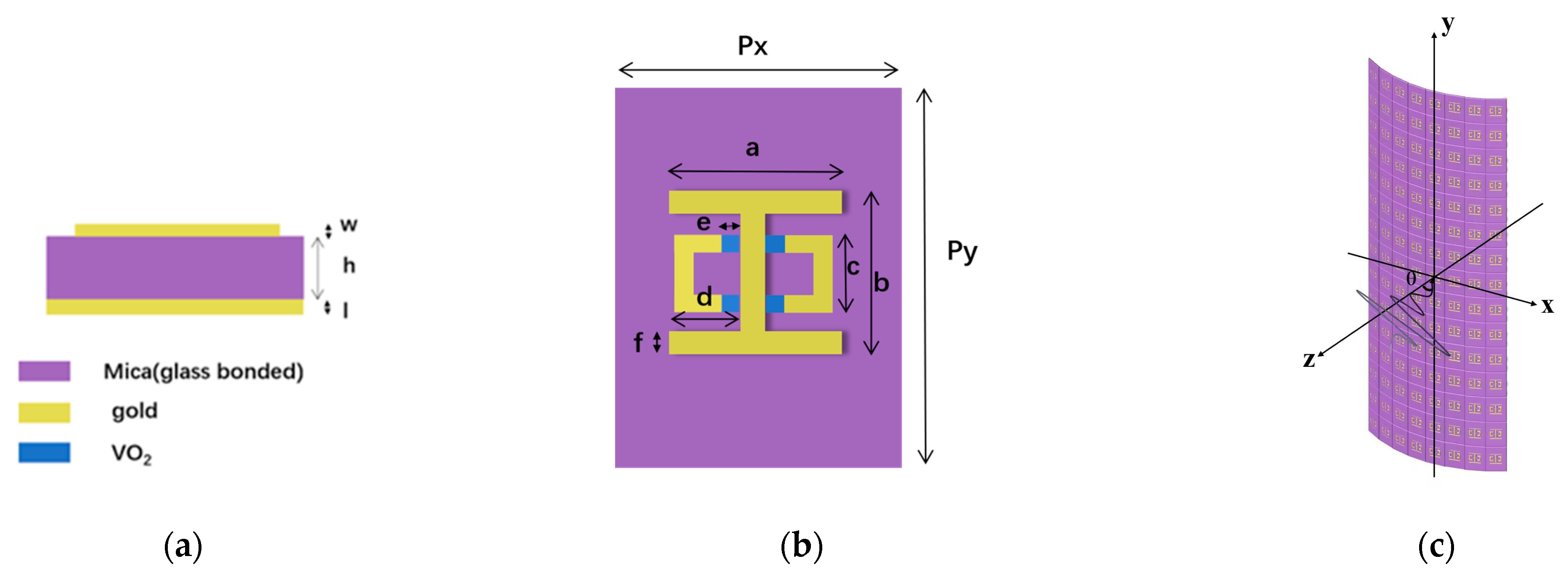
Figure 1. (a) Side view of the unit cell structure. (b) Top view of the unit cell structure. (c) Three-dimensional schematic diagram of the flexible MMA. The structure parameters are shown as follows: Px = 170 μm, Py = 240 μm, a = 120 μm, b = 100 μm, c = 70 μm, d = 47.5 μm, f = 5 μm, e = 7.5 μm, w = 0.3 μm, h = 40 μm, and l = 2 μm.
Photonics 10 00621 g001
Figure 2. (a) Absorption response at normal incidence angles. (bd) The corresponding electric field distribution, surface current density, and magnetic field intensity distribution at 0.24 THz, respectively. (eg) The corresponding electric field distribution, surface current density, and magnetic field intensity distribution at 0.46 THz, respectively.
Photonics 10 00621 g002aPhotonics 10 00621 g002b
Figure 3. (a,e) Resonance peaks of different structures at normal incidence, electric field distribution, surface current density and magnetic field distribution of (bd) I-shaped structure, electric field distribution, surface current density and magnetic field distribution of (fh) Split ring structure.
Photonics 10 00621 g003
Figure 4. (a) Absorption response and (b) absorption spectrum of 0.24 THz and 0.46 THz at different angles.
Photonics 10 00621 g004
Figure 5. (ad) The corresponding electric field distribution at different incidence angles at 0.24 THz. (eh) The corresponding electric field distribution at different incidence angles at 0.46 THz.
Photonics 10 00621 g005aPhotonics 10 00621 g005b
Figure 6. (ac) The corresponding electric field distribution, surface current density and magnetic field distribution at 0.24 THz. (df) The corresponding electric field distribution, surface current density and magnetic field distribution at 0.39 THz. (gi) The corresponding electric field distribution, surface current density and magnetic field distribution at 0.46 THz. (jl) The corresponding electric field distribution, surface current density and magnetic field distribution at 0.57 THz.
Photonics 10 00621 g006aPhotonics 10 00621 g006b
Figure 7. (a) Absorption diagram of different electrical conductivity with different incident angles at different frequencies. (b,c) Absorptance curves of the proposed absorber at 0.24 THz and 0.26 THz, respectively, with the variation of conductivity at different incidence angles. The conductivity of VO2 is 10 S/m, 1000 S/m, 10,000 S/m.
Photonics 10 00621 g007
Figure 8. (ac) The corresponding electric field distribution, surface current density and magnetic field distribution at 0.24 THz. (df) The corresponding electric field distribution, surface current density and magnetic field distribution at 0.46 THz. The THz wave is incident at 0 degrees.
Photonics 10 00621 g008
Figure 9. (ac) The corresponding electric field distribution, surface current density and magnetic field distribution at 0.25 THz. (df) The corresponding electric field distribution, surface current density and magnetic field distribution at 0.46 THz. The THz wave is incident at 0 degrees.
Photonics 10 00621 g009
Table 1. Comparison of the present MMA with others.
Ref.MaterialFrequency (THz)AbsorptionLayerThickness
(μm)
Flexible
[19]polyimide, copper0.72, 1.4, 2.3 89%, 98%, 85% three-layer16.2yes
[29]VO21.96Nearly 100%three-layer26no
[38]VO2, graphene0.75–1.15;
2.5–4.5
94%, 90%five-layer49.6no
[39]VO2 93.01–7.2790%three-layer7.4no
[40]Silicon, polyimide, copper0.33, 0.62, 0.82 98%, 96%, 98%four-layer69no
[41]VO2, graphene1.299.3%three-layer30.7no
[42]Si, SiO2, Au, graphene-41.7%three-layer0.94no
Our paperVO2, mica, gold0.24, 0.4699.7%, 99.3%three-layer42.3yes
Disclaimer/Publisher’s Note: The statements, opinions and data contained in all publications are solely those of the individual author(s) and contributor(s) and not of MDPI and/or the editor(s). MDPI and/or the editor(s) disclaim responsibility for any injury to people or property resulting from any ideas, methods, instructions or products referred to in the content.