Communication

Photoresponse of Graphene Channel in Graphene-Oxide–Silicon Photodetectors

1
Center for Condensed Matter Sciences and Graduate Institute of Electronics Engineering, National Taiwan University, Taipei 106, Taiwan
2
Graduate School of Advanced Technology Program for Semiconductor Devices, Materials, and Hetero-Integration, National Taiwan University, Taipei 106, Taiwan
3
Department of Mechanical Engineering, and Advanced Institute of Manufacturing with High-Tech Innovations, National Chung Cheng University, Chiayi County 62102, Taiwan
4
Department of Electronics Engineering, National Kaohsiung University of Science and Technology, Kaohsiung 807, Taiwan
*
Author to whom correspondence should be addressed.
Photonics 2023, 10(5), 568; https://doi.org/10.3390/photonics10050568
Submission received: 29 March 2023 / Revised: 3 May 2023 / Accepted: 8 May 2023 / Published: 12 May 2023
(This article belongs to the Special Issue Advanced Photonic Sensing and Measurement)

Abstract

:
Graphene-on-silicon photodetectors exhibit broadband detection capabilities with high responsivities, surpassing those of their counterpart semiconductors fabricated purely using graphene or Si. In these studies, graphene channels were considered electrically neutral, and signal amplification was typically attributed to the photogating effect. By contrast, herein, we show graphene channels to exhibit p-type characteristics using a structure wherein a thin oxide layer insulated the graphene from Si. The p-type carrier concentration is higher (six-times) than the photoaging-induced carrier concentration and dominates the photocurrent. Additionally, we demonstrate photocurrent tunability in the channel. By operating this device under a back-gated bias, photocurrent tuning is realized with not only amplification but also attenuation. Gate amplification produces a current equal to the photogating current at a low bias (0.2 V), and it is approximately two orders of magnitude larger at a bias of 2 V, indicating the operation effectiveness. Meanwhile, photocurrent attenuation enables adjustments in the detector output for compatibility with read-out circuits. A quantification model of gate-dependent currents is further established based on the simulation model used for metal–oxide–semiconductor devices. Thus, this study addresses fundamental issues concerning graphene channels and highlights the potential of such devices as gate-tunable photodetectors in high-performance optoelectronics.

1. Introduction

Photodetectors are key devices in optoelectronic systems used in our daily life [1,2,3]. Recently, graphene-on-silicon hybrid photodetectors have been developed with responsivity levels that are much larger than their counterparts constructed using only graphene or silicon, which make them promising candidates for high-performance optoelectronic systems [4,5,6,7,8]. The amplification behaviour is associated with the photogating effect where the graphene channel is electrically gated by the photoexcited carriers trapped at the heterointerface, resulting in additional carriers in the channel, which amplify the current. A wide responsivity range of 0.1–107 A/W is reported in the literature, with different procedures, which are summarized in [9,10]. Under this scheme, the photoresponse using different semiconductor materials has been demonstrated [11], showing that the spectra detection range is extended, and the cut-off wavelength is characterized by the material energy bandgap (for instance, by using Ge, the detection range extends from the visible region of Si to infrared region cut-off at bandgap of Ge) [12,13,14]. Structural engineering on the hybrid photodetector has also been developed. Riazimehr et al. [15] investigated the effect of placing SiO2 between graphene and Si on the graphene channel photocurrent using local scanning probe photocurrent measurements. They observed that the photocurrent in the graphene channel is higher than that observed using only a Si film. This observation was attributed to the inversion layer formed at the SiO2/Si interface due to the difference in work function of SiO2 and Si. These studies focused on the photodetector performance regarding responsivity, spectra detection range, and photogating effect [14,16]. In these discussions, graphene is treated as electrically neutral, i.e., without free carriers, and photocurrent is attributed to two carrier types: (a) additional carriers generated by the photogating effect and (b) photoexcited carriers transferred from semiconductor to graphene [17,18]. For n-type Si, holes transfer from Si to graphene, while for p-type Si, electrons transfer from Si to graphene caused by band bending at the heterointerface. Nevertheless, studies considering the electronic properties of graphene on semiconductors suggested that the graphene channel exhibited p-type characteristics owing to the atoms or molecules being attached on the structure during the fabrication process, as modelled theoretically [19,20]. In this case, the additional electrons are generated by the photogating effect or the transferred electrons will not accumulate but they will have a tendency to recombine with holes owing to the fast recombination time of graphene [21]. Consequently, the total number of carriers in the channel is reduced, reducing the photocurrent. Thus, identifying the graphene channel electrical type and intrinsic carrier concentrations in the channel is needed for assessing the hybrid detector performance.
Here, we present a hybrid photodetector design that addresses the intrinsic carrier effects on the photoresponse, and the photocurrent in the graphene channel can be tuned by using the back-gated bias. The proposed design comprises graphene and Si layers sandwiching a thin oxide, shown schematically in Figure 1a. The key functionalities of the oxide layer are two-fold: First, it electrically insulates graphene from Si so that only the graphene channel is examined. Second, it creates an energy barrier between graphene and Si, which prevents charge transfers that occur in the traditional hybrid structure [22,23]. The p-type electrical characteristic of the graphene channel is revealed by its current-voltage behaviour under back-gated bias (VBG). This carrier concentration is quantified based on a simple physical mode used in a metal-oxide–semiconductor (MOS) device (where the carrier concentration in the channel is modulated by the gate bias). These intrinsic carriers result in a background current embedded in the photocurrent, the magnitude of which is even larger than the current induced by traditional photogating. Tunability regarding both photocurrent amplification and attenuation is demonstrated with respect to VBG. An amplified photocurrent that is larger than the current generated by photogating is achieved at low bias, underlining the performance enhancements due to the VBG. The photocurrent attenuation is also useful because it allows for adjusting the detector output to avoid saturating the read-out circuit under intense illumination.

2. Methodology

The designed device was fabricated in three steps. First, a thin SiO2 layer was grown on n-type Si wafer with a resistivity of 5 Ohm cm at a temperature of 400 °C in the presence of a dry oxygen flow at atmospheric pressure. The thickness of oxide layer was characterized to be 2.7 ± 0.2 nm based on the measurement of High-resolution Transmission Electron Microscopy (HTEM). Secondly, two rectangular metal pads (made of 50 nm Ti/120 nm Au) were then deposited on top of the SiO2 layer with a separation of 0.6 mm using an e-gun evaporator. Finally, monolayer graphene was transferred to the top of the sample through a wet transfer process. The device was then examined via Raman microscopy to ensure the formation of graphene on the oxide layer. Two features at 1579 cm−1 and 2708 cm−1 were found in Raman spectra ensuring the successful fabrication (these characterizations are described in detail in the Supplementary Information S1).
The working principles of the designed device under illumination and VBG are illustrated using the equilibrium energy profile of the structure depicted in Figure 1b. This energy profile exhibits a band bending at the SiO2/Si interface, which is associated with the carrier flow when lining up the Fermi levels of graphene and Si. The equilibrium energy profile is discussed in detail in the Supplementary Information S2. Under illumination, most light transmission occurs through graphene and SiO2 reaching the Si wafer, generating an electron–hole pair. These carriers are spatially redistributed owing to a built-in electric field where electrons move toward the Si bulk while holes move in the opposite direction toward the SiO2/Si interface trapped at the low energy potential. Under the other operation conditions, positive VBG is applied at the back of the device, which drives electrons toward the Si bulk, leaving positive ions accumulated at SiO2/Si interface. For both operation types, positive charges are presented at the interface. This functions as an electrical gate to the graphene channel that induces electron generation in the channel, altering photoresponse of the channel. Experimental result and analysis are discussed below. The charge distribution at the interface is illustrated schematically in Figure 1b.
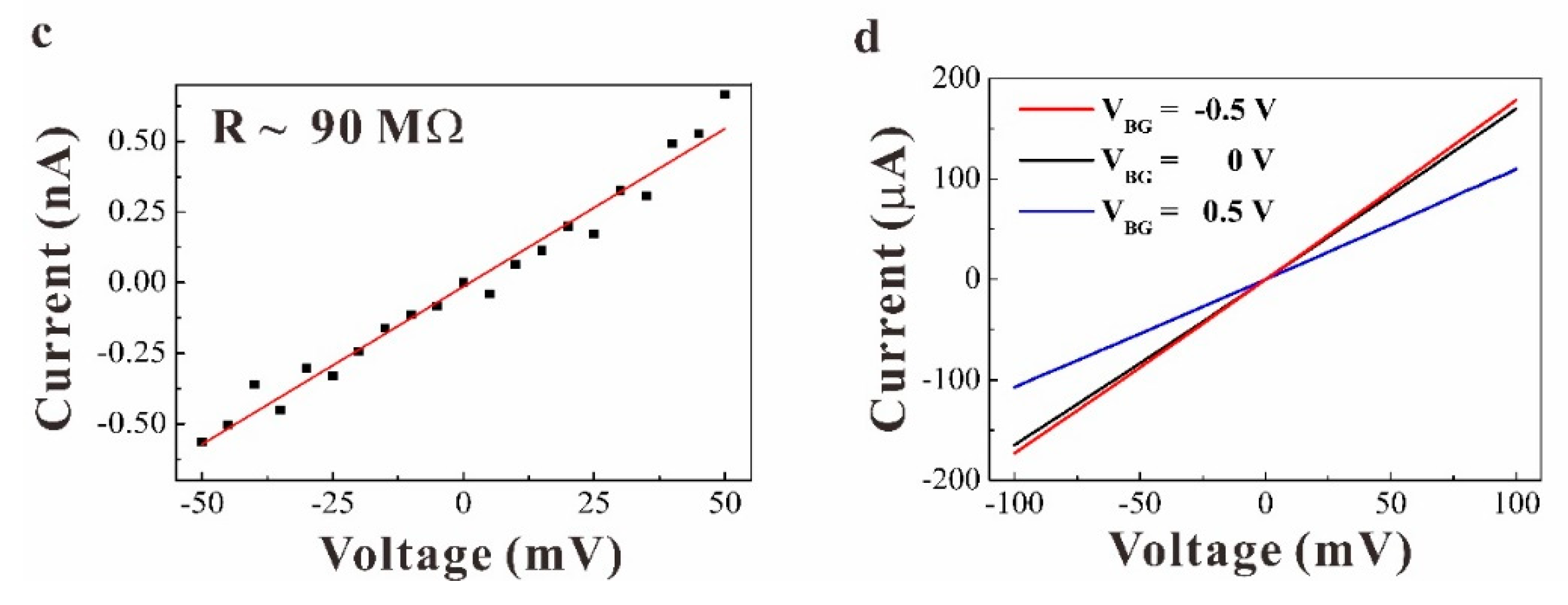
The device performance depends critically on the insulation between graphene and Si [24,25]. This insulation is examined with respect to the current-voltage (I-V) characteristic measured across the top- and back-side electrodes in a dark environment. The resulting trace is plotted in Figure 1c. A high resistance of 90 MΩ is recorded, which agrees well with the value deduced from the SiO2 bulk. The resistance of the SiO2 bulk is 30 Ω cm with respect to the oxide thickness used in the proposed structure, which yields a resistance of 95 MΩ. I-V trace of the graphene channel is depicted in Figure 1d. From the figure, a resistance of 150 Ω/□ can be observed, which is approximately six-times smaller than that of the free-standing graphene layer [26,27]. This result underlines that the film is doped through the fabrication process.

3. Results and Discussions

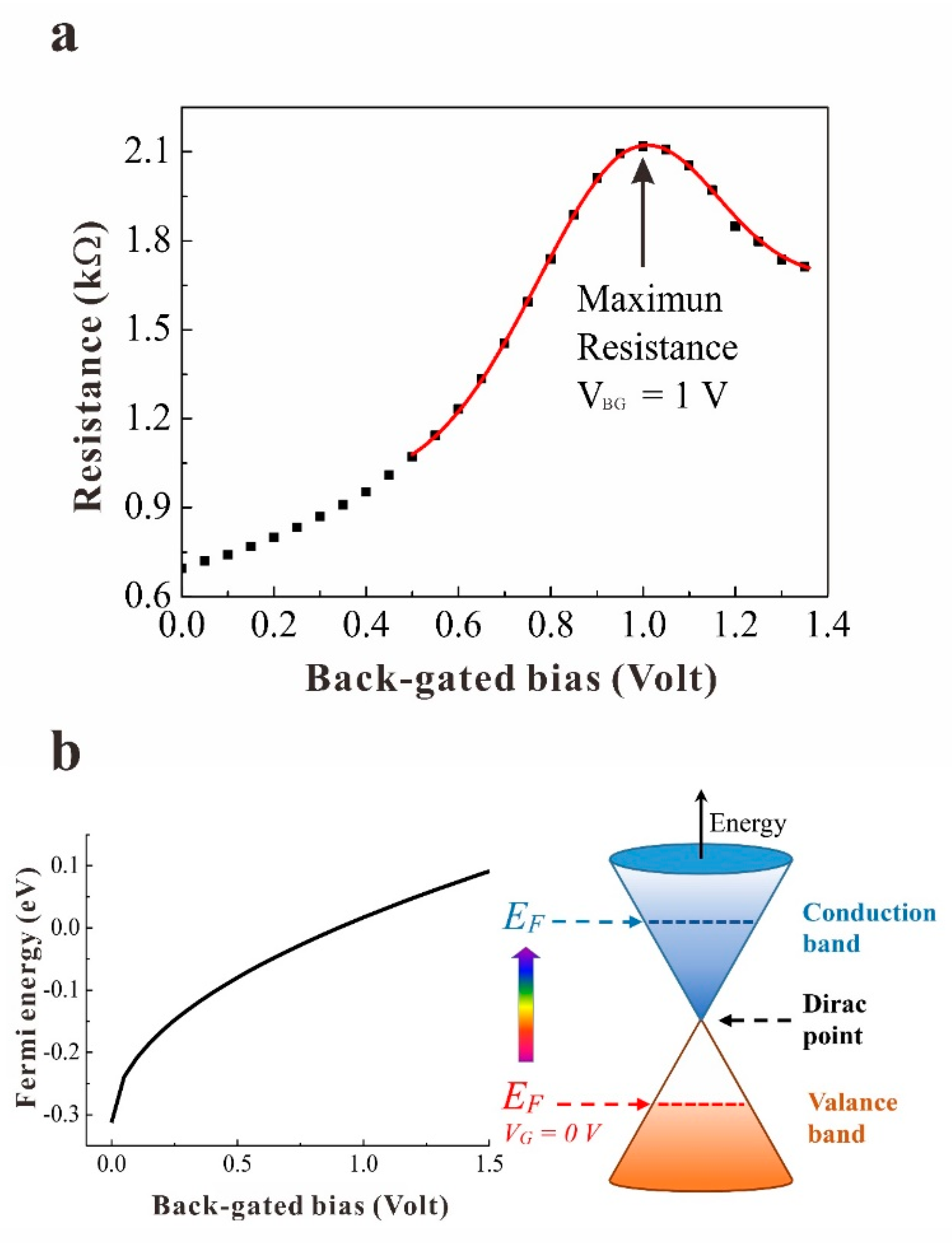
Before showing the amplification in the photocurrent, we first discuss the electrical characteristics of the graphene channel. Figure 2a plots the resistance (R) as a function of the positive VBG measured in a dark environment under short-circuit conditions with the graphene layer grounded. R is measured with a fixed voltage of 0.1 V applied across the two electrodes on graphene. Five experiments were conducted for each voltage, for which the R value was determined from the corresponding mean value and the standard derivation for the R value was less than 0.5% of the mean value. The behaviour of R is categorized into two operating regions: First, R increases with increasing VBG, reaching a maximum value at a critical voltage of 1 V. Then, it decreases when VBG is further increased up to the maximum applied voltage. The carrier types in the graphene channel are identified observing R behaviour at low VBG values. The applied VBG induced electron generation in the graphene channel, as described above. In the presence of these induced electrons, if the graphene channel is n-type-doped, then adding the induced electrons should increase the total amount of electrons, resulting in a decrease in resistance. However, the data indicate an opposite trend. Thus, the hole is denoted as the intrinsic carrier in which the induced electrons recombine, reducing the total amount of holes in the channel and increasing the measured R values. The increase in VBG continues to reduce the hole concentration in the channel, shifting the corresponding Fermi level located at the valence band toward the Dirac point (charge neutrality point) where the resistance is maximum [28]. A further increase in VBG shifts the Fermi energy across the Dirac point to the conduction band. Above this critical voltage, as holes are depleted, electrons start to accumulate in the channel, which decreases R illustrated by the R behaviour at high VBG values. This sweeping of Fermi energy based on VBG is shown schematically in Figure 2b. When establishing p-type characteristics of the graphene channel, the obtained result highlights the tunability of carrier concentration with notably changing the carrier type (from hole to electron) in electric transport in the channel owing to the VBG.
The intrinsic hole concentration (Ng) in the channel can be found based on the R characteristic [29]. As discussed above, Ng is equal to the number of induced electrons at the critical voltage. The induced electrons are estimated by the model used for the MOS device, which is εOXVBG/ed. Here, εOX and d are the dielectric constant and SiO2 layer thickness (εOX = 3.9ε0, d = 2.7 nm), respectively, and e is the free electron charge. Considering an experimental value of VBG, that is, 1 V, results in an electron concentration of 7.99 × 1012 cm−2, which is equal to Ng. This intrinsic hole concentration induces a background current (dark current) embedded in the photocurrent discussed below. R behaviour under bias and its associated Ng are examined on two other devices fabricated with the same procedure. Similar R behaviour is observed with a small deviation at the critical voltage value; see the Supplementary Information S3 for details. The associated Ng yields a deviation of ±3.1%.
Next, we proceed to examine the device photoresponse, which is characterized by the background current discussed above and current due to the photogating effect. Photogating current is resolved through the AC detection scheme using a lock-in amplifier, which records the difference between the current in a dark environment and under illumination [30]. A change of 2.5 μA is measured with a laser wavelength of 1064 nm at a power of 0.4 W/cm2 (DC measurement is also conducted, and it gives a consistent result; see Supplementary Information Section S1). This is mainly associated with a reduction in intrinsic hole concentration due to the recombination of holes with photogenerated electrons. The change in hole concentration ( Δ n ) is 1.31 × 1012 cm−2 based on the following estimation: Δ I = ( W / L ) Δ n μ V , where W and L denote the device width and length, respectively, μ is hole mobility extracted via the trans conductance measurement on the device (see Supplementary Information S4 for details), and V is applied voltage of 0.1 V. To obtain a good approximation, the electron concentration generated via photogating is set to this value as well [31]. Compared with Ng, the result is approximately six-times smaller, which underlines the dominance of the background carrier in the photocurrent. Subsequently, quantifying the intrinsic carrier concentration and photogating carrier is crucial for the photoresponse. The photocurrent measurement is also performed at two other laser wavelengths of 633 and 808 nm at a power of 0.26 W/cm2. The results yield a similar Δ n value.
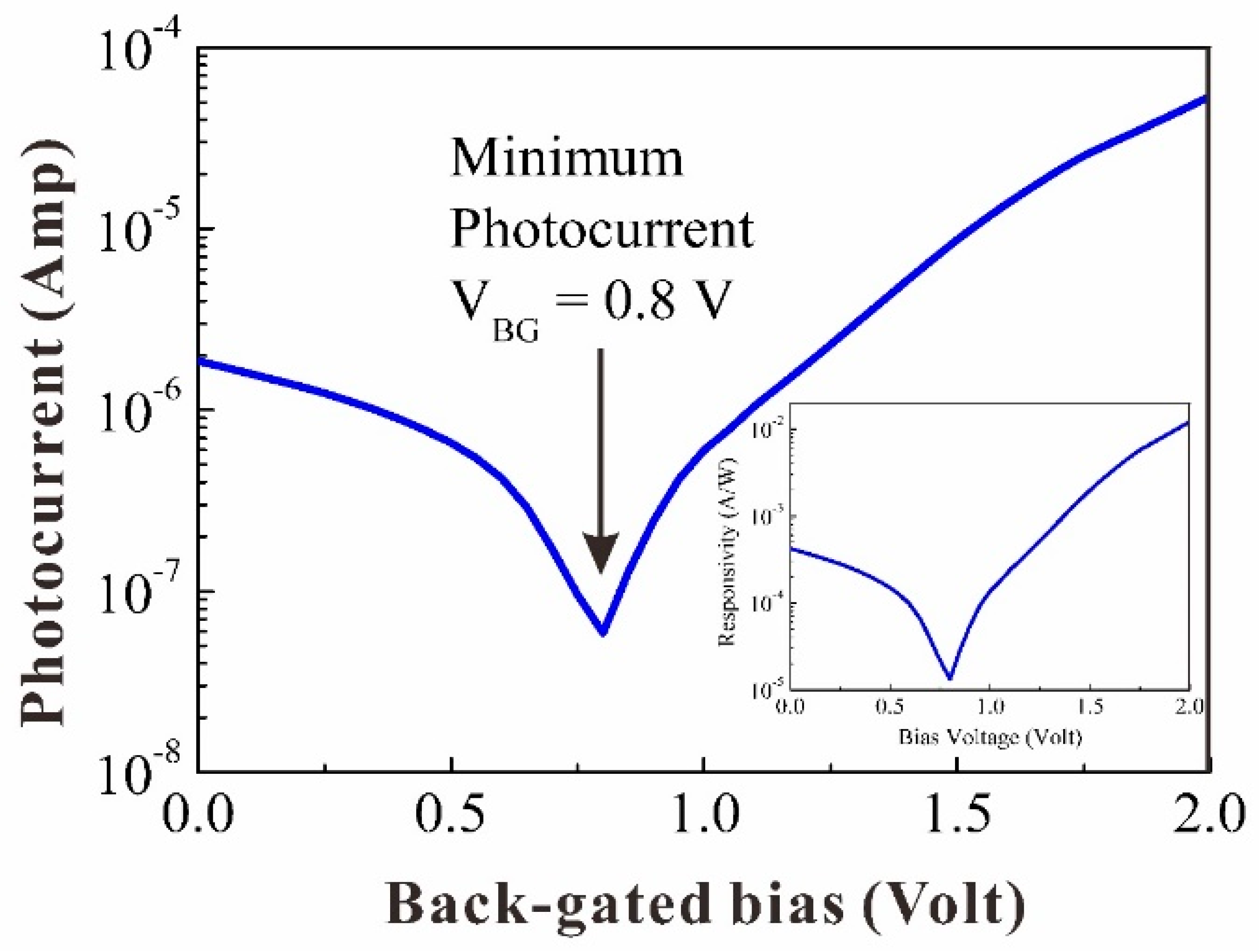
The photocurrent in the graphene channel can also be varied using the VBG as it induces electron generation in the channel, evident in the R versus VBG characteristics illustrated in Figure 2a. Figure 3 depicts the photocurrent recorded as a function of VBG, in which two characteristics are depicted: First, the photocurrent decreases as VBG is applied, reaching a minimum at a bias of 0.8 V. Then, it starts to increase as VBG increases further. Similar photocurrent characteristics are also observed at laser wavelengths of 633 and 808 nm (see Supplementary Information S5 for details). This decrease-to-increase characteristic can be assessed observing the changes in hole concentration and carrier type with respect to VBG. The hole concentration reduces at first as VBG is applied. Accordingly, holes are depleted at the critical voltage where the number of holes is equal to the number of induced electrons. Then, electrons start to accumulate as VBG increases further. Note that the continuing electron increase in the channel at VBG is approximately equal to 1.2 V, resulting in a photocurrent comparable to that measured without VBG, while approximating two orders of magnitude at 2 V. This demonstrates the potential of the proposed device to serve as a tuneable detector for enhancing the photocurrent in applications requiring high-responsivity detection.
As illustrated above, both VBG and photogating affect the graphene channel photoresponse. However, both effects induce electron generation in the graphene channel, VBG generates a tuneable number of electrons depending on the magnitude of applied bias voltage, while the photogating effect yields a fixed number of electrons (at a fixed power). Owing to this tunability, an electron concentration equal to that generated by the photogating effect at low VBG, that is, 0.2 V determined based on the formula εOXVBG/ed, can be obtained. This electron concentration increases as VBG increases and becomes approximately two orders of magnitude at 2 V, providing an effective approach for modulating the carrier concentration (hence, photocurrent) in the graphene channel. The corresponding responsivity is plotted in the insert of Figure 3. At zero bias, it exhibits a value of 0.4 mA/W. This value is consistent with those previous reports on graphene photodetectors where the responsivity is limited to approximately mA/W due to the short lifetime of photogenerated carriers in graphene and the weak optic absorption. The applied bias changes the responsivity and at VBG = 2 Volt, responsivity is amplified by about two orders of larger magnitude. Although this scale (tens of mA/W) is lower than those graphene-on-Si hybrid structures [6,7], nevertheless, it can be further enhanced by increasing the bias. In addition to the bias, notice that another key parameter affecting the performance is the oxide layer thickness. A thinner oxide layer would generate more electrons under the same applied bias, thus yielding a larger responsivity. Unlike the existing research, which used a thick oxide layer (hundreds of nanometres), we adopted a thin oxide layer at the electronic device level. A thick oxide layer results in many fewer electrons because the number of generated electrons is inversely proportional to the layer thickness. Subsequently, we observed the pronounced behaviour when tuning the photocurrent.

4. Conclusions

In summary, the design of a hybrid photodetector was presented that reveals the unique p-type electrical characteristic and tuneable photoresponse characteristics of a graphene channel. The p-type characteristics introduce a key photocurrent factor that dominates the photocurrent instead of the conventional photogating effect. This factor provides a possible explanation for the wide range of responsivity reported in the literature (from 1 A/W to 107 A/W), as the devices were fabricated via a different process with different doping concentrations in the graphene channel. By tuning the photocurrent with back-gated bias, an amplified photocurrent that is larger than the current generated by photogating shows the effectiveness of enhancing the performance using a VBG. In addition to enhancing the performance, more importantly, it can also attenuate the photocurrent that regulates the detector output current, providing a key functionality for further integration with the read-out circuit of an optoelectronic system.

Supplementary Materials

The following supporting information can be downloaded at: https://www.mdpi.com/article/10.3390/photonics10050568/s1, see Supplementary Material for (S1) device fabrication process, TEM characterization on oxide thickness, SEM characterization on device, Raman examination on the formation of graphene on SiO2/Si, and photocurrent measurement, (S2) equilibrium energy profile described in details, (S3) resistance behavior of other devices, (S4) hole mobility of graphene channel, (S5) photocurrent measurement with laser wavelengths of 808 and 633 nm. References [32,33,34,35,36,37] are cited in the Supplementary Material.

Author Contributions

H.H.C. and K.-M.H. conceived and designed the experiment, led the research, and wrote the paper. K.-C.L., H.L. and G.-E.C. contributed to material synthesis and device fabrication. Y.-H.C. and C.-K.H. performed the measurement. All authors have read and agreed to the published version of the manuscript.

Funding

This research was funded by Ministry of Science and Technology of the Republic of China (MOST 111-2112-M-002-041 and MOST 112-2923-M-002-004).

Institutional Review Board Statement

Not applicable.

Informed Consent Statement

Not applicable.

Data Availability Statement

The data that support the findings of this study are available from the corresponding author upon reasonable request.

Acknowledgments

We would like to thanks the reviewers and editors for their suggestions and assistance to improve this article.

Conflicts of Interest

The authors have no conflict to disclose.

References

  1. Koppens, F.H.L.; Mueller, T.; Avouris, P.; Ferrari, A.C.; Vitiello, M.S.; Polini, M. Photodetectors based on graphene, other two-dimensional materials and hybrid systems. Nat. Nanotechnol. 2014, 9, 780–793. [Google Scholar] [CrossRef] [PubMed]
  2. Rogalski, A.; Kopytko, M.; Martyniuk, P. Two-dimensional infrared and terahertz detectors: Outlook and status. Appl. Phys. Rev. 2019, 6, 021316. [Google Scholar] [CrossRef]
  3. Capista, D.; Lozzi, L.; Pelella, A.; Di Bartolomeo, A.; Giubileo, F.; Passacantando, M. Spatially Resolved Photo-Response of a Carbon Nanotube/Si Photodetector. Nanomaterials 2023, 13, 650. [Google Scholar] [CrossRef] [PubMed]
  4. Rehman, M.A.; Park, S.; Khan, M.F.; Bhopal, M.F.; Nazir, G.; Kim, M.; Farooq, A.; Ha, J.; Rehman, S.; Jun, S.C.; et al. Development of directly grown-graphene–silicon Schottky barrier solar cell using co-doping technique. Int. J. Energy Res. 2022, 46, 11510–11522. [Google Scholar] [CrossRef]
  5. Pelella, A.; Grillo, A.; Faella, E.; Luongo, G.; Askari, M.B.; Di Bartolomeo, A. Graphene−Silicon Device for Visible and Infrared Photodetection. ACS Appl. Mater. Interfaces 2021, 13, 47895–47903. [Google Scholar] [CrossRef]
  6. Jiang, J.; Wen, Y.; Wang, H.; Yin, L.; Cheng, R.; Liu, C.; Feng, L.; He, J. Recent Advances in 2D Materials for Photodetectors. Adv. Electron. Mater. 2021, 7, 2001125. [Google Scholar] [CrossRef]
  7. Wang, Y.; Ho, V.X.; Pradhan, P.; Cooney, M.P.; Vinh, N.Q. Effect of High-κ Dielectric Layer on 1/f Noise Behavior in Graphene Field-Effect Transistors. ACS Appl. Nano Mater. 2021, 4, 8539–8545. [Google Scholar] [CrossRef]
  8. Zhang, Y.; Liu, T.; Meng, B.; Li, X.; Liang, G.; Hu, X.; Wang, Q.J. Broadband high photoresponse from pure monolayer graphene photodetector. Nat. Commun. 2013, 4, 1811. [Google Scholar] [CrossRef]
  9. Scagliotti, M.; Salvato, M.; Crescenzi, M.D.; Mishra, N.; Fabbri, F.; Miseikis, V.; Coletti, C.; Catone, D.; Mario, L.D.; Boscardin, M.; et al. Large-area, high-responsivity, fast and broadband graphene/n-Si photodetector. Nat. Nanotechnol. 2021, 32, 155504. [Google Scholar] [CrossRef]
  10. Fukushima, S.; Shimatani, M.; Okuda, S.; Ogawa, S.; Kanai, Y.; Ono, T.; Inoue, K.; Matsumoto, K. Photogating for small high-responsivity graphene middle-wavelength infrared photodetectors. Opt. Eng. 2020, 59, 037101. [Google Scholar] [CrossRef]
  11. Elahi, E.; Khan, M.F.; Rehman, S.; Khalil, H.M.W.; Rehman, M.A.; Kim, D.; Kim, H.; Khan, K.; Shahzad, M.; Iqbal, M.W.; et al. Enhanced electrical and broad spectral (UV-Vis-NIR) photodetection in a Gr/ReSe2/Gr heterojunction. Dalton Trans. 2020, 49, 10017–10027. [Google Scholar] [CrossRef] [PubMed]
  12. Zeng, L.H.; Wang, M.Z.; Hu, H.; Nie, B.; Yu, Y.Q.; Lu, C.Y.; Wang, L.; Hu, J.G.; Xie, C.; Liang, F.X.; et al. Monolayer Graphene/Germanium Schottky Junction As High-Performance Self-Driven Infrared Light Photodetector. ACS Appl. Mater. Interfaces 2013, 5, 9362–9366. [Google Scholar] [CrossRef] [PubMed]
  13. Lv, Y.; Li, H.; Lee, K.C.; Chang, G.E.; Shieh, T.H.; Wu, X.S.; Chang, C.R.; Wu, H.C.; Hung, K.M.; Cheng, H.H. Amplifying photocurrent of graphene on GeSn film by sandwiching a thin oxide between them. Appl. Phys. Lett. 2020, 117, 152106. [Google Scholar] [CrossRef]
  14. Yang, F.; Yu, K.; Cong, H.; Xue, C.; Cheng, B.; Wang, N.; Zhou, L.; Liu, Z.; Wang, Q. Highly Enhanced SWIR Image Sensors Based on Ge1–xSnx–Graphene Heterostructure Photodetector. ACS Photonics 2019, 6, 1199–1206. [Google Scholar] [CrossRef]
  15. Riazimehr, S.; Kataria, S.; Bornemann, R.; Bolivar, P.H.; Ruiz, F.J.G.; Engstrom, O.; Godoy, A.; Lemme, M.C. High Photocurrent in Gated Graphene–Silicon Hybrid Photodiodes. ACS Photonics 2017, 4, 1506–1514. [Google Scholar] [CrossRef]
  16. Fukushima, S.; Shimatani, M.; Okuda, S.; Ogawa, S.; Kanai, Y.; Ono, T.; Inoue, K.; Matsumoto, K. Low dark current and high-responsivity graphene mid-infrared photodetectors using amplification of injected photo-carriers by photo-gating. Opt. Lett. 2019, 44, 2598–2601. [Google Scholar] [CrossRef]
  17. Kobayashi, S.; Anno, Y.; Takei, K.; Arie, T.; Akita, S. Photoresponse of graphene field-effect-transistor with n-type Si depletion layer gate. Sci. Rep. 2018, 8, 4811. [Google Scholar] [CrossRef]
  18. Park, H.K.; Choi, J. High Responsivity and Detectivity Graphene-Silicon Majority Carrier Tunneling Photodiodes with a Thin Native Oxide Layer. ACS Photonics 2018, 5, 2895–2903. [Google Scholar] [CrossRef]
  19. Leenaerts, O.; Partoens, B.; Peeters, F.M. Adsorption of H2O, NH3, CO, NO2, and NO on graphene: A first-principles study. Phys. Rev. B 2008, 77, 125416. [Google Scholar] [CrossRef]
  20. Hernandez, M.; Oca, A.C.M.D.; Leyva, M.O.; Naumis, G.G. How water makes graphene metallic. Phys. Lett. A 2019, 383, 125904. [Google Scholar] [CrossRef]
  21. Rana, F. Electron-hole generation and recombination rates for Coulomb scattering in graphene. Phys. Rev. B 2007, 76, 155431. [Google Scholar] [CrossRef]
  22. Yan, R.; Zhang, Q.; Li, W.; Calizo, I.; Shen, T.; Richter, C.A.; Walker, A.R.H.; Liang, X.; Seabaugh, A.; Jena, D.; et al. Determination of graphene work function and graphene-insulator-semiconductor band alignment by internal photoemission spectroscopy. Appl. Phys. Lett. 2012, 101, 022105. [Google Scholar] [CrossRef]
  23. Bartolomeo, A.D. Graphene Schottky diodes: An experimental review of the rectifying graphene/semiconductor heterojunction. Phys. Rep. 2016, 606, 1–58. [Google Scholar] [CrossRef]
  24. Xu, K.; Zeng, C.; Yan, R.; Ye, P.; Wang, K.; Seabaugh, A.C.; Xing, H.G.; Suehle, J.S.; Richter, C.A.; Gundlach, D.J.; et al. Direct Measurement of Dirac Point Energy at the Graphene/Oxide Interface. Nano Lett. 2013, 13, 131–136. [Google Scholar] [CrossRef] [PubMed]
  25. Rehman, M.A.; Akhtar, I.; Choi, W.; Akbar, K.; Farooq, A.; Hussain, S.; Shehzad, M.A.; Chun, S.H.; Jung, J.; Seo, Y. Influence of an Al2O3 interlayer in a directly grown graphene-silicon Schottky junction solar cell. Carbon 2018, 132, 157–164. [Google Scholar] [CrossRef]
  26. Peng, S.A.; Jin, Z.; Ma, P.; Zhang, D.Y.; Shi, J.Y.; Niu, J.B.; Wang, X.Y.; Wang, S.Q.; Li, M.; Liu, X.Y.; et al. The sheet resistance of graphene under contact and its effect on the derived specific contact resistivity. Carbon 2015, 82, 500–505. [Google Scholar] [CrossRef]
  27. Wang, Q.; Kitaura, R.; Suzuki, S.; Miyauchi, Y.; Yamamoto, K.M.Y.; Arai, S.; Shinohara, H. Fabrication and In Situ Transmission Electron Microscope Characterization of Free-Standing Graphene Nanoribbon Devices. ACS Nano 2016, 10, 1475–1480. [Google Scholar] [CrossRef]
  28. Craciun, M.F.; Russo, S.; Yamamoto, M.; Tarucha, S. Tuneable electronic properties in graphene. Nano Today 2011, 6, 42–60. [Google Scholar] [CrossRef]
  29. Luo, F.; Zhu, M.; Tan, Y.; Sun, H.; Luo, W.; Peng, G.; Zhu, Z.; Zhang, X.A.; Qin, S. High responsivity graphene photodetectors from visible to near-infrared by photogating effect. AIP Adv. 2018, 8, 115106. [Google Scholar] [CrossRef]
  30. Liu, F.; Kar, S. Quantum Carrier Reinvestment-Induced Ultrahigh and Broadband Photocurrent Responses in Graphene–Silicon Junctions. ACS Nano 2014, 8, 10270–10279. [Google Scholar] [CrossRef]
  31. Guo, X.; Wang, W.; Nan, H.; Yu, Y.; Jiang, J.; Zhao, W.; Li, J.; Zafar, Z.; Xiang, N.; Ni, Z.; et al. High-performance graphene photodetector using interfacial gating. Optical 2016, 3, 1066–1070. [Google Scholar] [CrossRef]
  32. ACS Material. Available online: https://www.acsmaterial.com/ (accessed on 1 May 2023).
  33. Stubrov, Y.; Nikolenko, A.; Gubanov, V.; Strelchuk, V. Manifestation of Structure of Electron Bands in Double-Resonant Raman Spectra of Single-Walled Carbon Nanotubes. Nanoscale Res. Lett. 2016, 11, 2. [Google Scholar] [CrossRef] [PubMed]
  34. Heo, G.; Kim, Y.S.; Chun, S.H.; Seong, M.J. Polarized Raman spectroscopy with differing angles of laser incidence on single-layer graphene. Nanoscale Res. Lett. 2016, 10, 45. [Google Scholar] [CrossRef]
  35. Han, M.Y.; Özyilmaz, B.; Zhang, Y.; Kim, P. Energy Band-Gap Engineering of Graphene Nanoribbons. Phys. Rev. Lett. 2007, 98, 206805. [Google Scholar] [CrossRef] [PubMed]
  36. Chen, Z.; Appenzeller, J. Mobility Extraction and Quantum Capacitance Impact in High Performance Graphene Field-effect Transistor Devices. IEEE Int. Electron Dev. Meet. 2008, 21, 509. [Google Scholar]
  37. Guo, X.; Wang, W.; Nan, H.; Yu, Y.; Jiang, J.; Zhao, W.; Li, J.; Zafar, Z.; Xiang, N.; Ni, Z.; et al. High-performance graphene photodetector using interfacial gating. Optical 2016, 3, 1066. [Google Scholar] [CrossRef]
Figure 1. Structure and characteristic of the device. (a) Schematic of the device layer structure and electrical measurement set-up for the IV measurement. (b) Schematic energy band profile of p-type graphene/SiO2/n-Si, photoexcited carrier transport under illumination, and positive ion locations under positive back-gated bias. Red (white) solid arrow line represents the direction of motion of a photoexcited electron (hole). These electrons (holes) are represented by red (white) solid circles. VBG induces positive ions are white solid circles with a red cross inside. (c) IV trace measured between graphene and Si with a high resistance of 90 MΩ, reflecting the electrical insulation between the two layers. (d) IV trace of the graphene layer with a resistance of approximately 600 Ω.
Photonics 10 00568 g001aPhotonics 10 00568 g001b
Figure 2. Graphene channel electrical characteristics. (a) Resistance of the graphene layer at different gate bias voltages. The maximum resistance is 2.12 kΩ when the back-gated bias (VBG) = 1 V. (b) Left plot: bias-dependent Fermi level of graphene plotted as a function of the bias voltage. Right plot: a representative view of the Fermi level (EF) shift in the graphene layer under applied bias voltage. The rainbow arrow indicates a Fermi level shift from the valence band to the conduction band under applied bias.
Photonics 10 00568 g002
Figure 3. Photocurrent as a function of back-gated voltage. Photocurrent as a function of back-gated bias with a fixed voltage 0.1 V under the wavelength λ = 1064 nm. The photocurrent showed the minimum peak at VBG = 0.8 V. The inset shows the responsivity characteristics at a power of 0.4 W/cm2.
Photonics 10 00568 g003
Disclaimer/Publisher’s Note: The statements, opinions and data contained in all publications are solely those of the individual author(s) and contributor(s) and not of MDPI and/or the editor(s). MDPI and/or the editor(s) disclaim responsibility for any injury to people or property resulting from any ideas, methods, instructions or products referred to in the content.