Communication

Application of Crossed Polarizer Method in the Measurement of Differential Group Delay of Optical Fibers

1
School of Physical Sciences, University of Science and Technology of China, Hefei 230026, China
2
Key Laboratory of High Power Laser Materials, Shanghai Institute of Optics and Fine Mechanics, Chinese Academy of Sciences, Shanghai 201800, China
3
Hangzhou Institute for Advanced Study, University of Chinese Academy of Sciences, Hangzhou 310024, China
4
Laser Institute, Qilu University of Technology (Shandong Academy of Sciences), Qingdao 266000, China
*
Authors to whom correspondence should be addressed.
Photonics 2023, 10(5), 518; https://doi.org/10.3390/photonics10050518
Submission received: 31 March 2023 / Revised: 25 April 2023 / Accepted: 26 April 2023 / Published: 1 May 2023
(This article belongs to the Topic Advance and Applications of Fiber Optic Measurement)

Abstract

:
In this paper, we report the use of crossed polarizer technique to measure the differential group delay (DGD) of few-mode optical fiber (FMF). The windowed Fourier transform (WFT) is applied in the analysis of beat length measurement in the spectral domain to obtain the dependence of DGD as a function of wavelength. The birefringence of polarization-maintaining fiber (PMF) and the DGD of FMF are measured by applying our method. We discuss the noise background, the width of DGD peaks, and the possible errors introduced in the optical path in the modified crossed polarizer technique.

1. Introduction

Few-mode fibers (FMFs) find key applications in large-capacity optical telecommunication due to the development of mode division multiplexing (MDM) technology [1,2,3,4]. The proper design of differential group delay (DGD) and dispersion plays a key role in the performance of remote communication systems [5,6,7,8].
Generically, DGD measurement is categorized into the time-of-flight (TOF) and interferometric techniques, including complex-transfer-function (CTF) methods [9,10,11], Rayleigh scattering methods, optical low-coherence interferometry/reflectometry (OLCI/OLCR) techniques, and spectral interferometric methods. It is difficult for the TOF technique to measure the DGD of a fiber that is a few meters long since it requires the signals to be well separated temporally. For a high resolution, the measurement using TOF must require a significantly longer length of fiber sample to well distinguish the modal delay [12]. Rayleigh scattering methods employ the effect of polarization dependence of the Rayleigh scattering [13,14,15]. In contrast, OLCI/OLCR merely needs a short sample where a high resolution is also achieved by measuring the wavelength dependence of modal group delay difference [16,17]. Spectral interferometric methods measure the DGD by analyzing the amplitude or spectrum of the interferometer [18,19,20,21,22,23,24,25,26,27,28,29,30]. In this case, analyzing the data with a window Fourier transform (WFT) can be very useful. This spectrogram approach has been proposed for data taken by S2 (Spatially and Spectrally resolved imaging) [31,32]. In summary, all DGD measurement techniques require relatively complex configurations of the experimental setup, and some may not be easily accessible.
The crossed polarizer technique is a simple measurement that is usually applied in the characterization of birefringence of polarization maintaining fiber. It has been reported in the measurement of DGD of FMF [33] by inverse Fourier transformation of each spectrum component of the interference waveform. However, such a method requires a significant amount of work to process each spectrum component separately. In this paper, we demonstrate the crossed polarizer technique in the measurement of DGD of FMF where WFT is utilized in the analysis of the measurement of beat length in the spectral domain. Instead of building a complex and expensive experimental configuration, a broadband light source, polarizer, and an optical spectral analyzer (OSA) are required to set up the experiment where the differential modal dispersion can be fully resolved.

2. Experiment Setup and Theoretic Model

Figure 1 shows our experimental setup which is similar to [21]. A broadband polarizer (P) is placed in front of the source to ensure that only one polarization state of the output from a broadband source is launched into the fiber under test (FUT) via lens L1. The output of FUT passes through an analyzer (A) before being coupled into a short single-mode fiber (SMF). The analyzer ensures that the polarization states of the modes are aligned on the SMF end-face. The SMF is connected to an optical spectrum analyzer (OSA).
The spectral beating I ω out of modal interference measured by OSA is expressed as follows (detailed derivation can be found in reference [23,34,35]):
I ω = I ¯ ω 1 + α m n cos ω τ m n
where ω denotes the angular frequency, I ¯ ω is the background intensity, τ m n is the DGD of m t h and n t h modes, α m n is the normalized amplitude of interference between m t h and n t h modes, and L is the length of FUT. The DGD is obtained by distinguishing the location of peaks in the Fourier transform (FT) of spectral beating, which is written as,
F τ = F ¯ τ + α m n F ¯ ( τ τ m n ) + F ¯ ( τ + τ m n )
where F ¯ τ = I ¯ ω e i τ ω d ω .
Equation (2) is derived under the assumption that τ m n is independent of wavelength because of the limited narrow band of the light source so that the dependence of modal group delay difference on the wavelength is neglected, thus the spectral beat frequencies are assumed constants in the measurement. In this way, by either applying the FT or even counting the spectral fringes directly, the group birefringence can be calculated accordingly. However, this assumption fails when the band of the light source is broader, or the dependence of DGD measurement on the wavelength needs to be measured.
FT reflects the global properties and lacks the capability to map the local features of the signal [36]. Instead, we applied WFT [37] in processing the spectral fringes out of the modal interference where the DGD shows a strong dependence on the wavelength:
S ξ , τ = I ω g ω ξ e i τ ω d ω
where S ξ , t denotes the WFT spectrum. g ω is a window to sample, and a Hann window is used throughout this paper, which is defined by:
g ω = 1 2 1 cos 2 π ω / σ ω σ 0 o t h e r w i s e
where the parameter σ controls the length of the Hann window. It should be noted that we compared the Gaussian window, Hamming, and Hann window in the data analysis and barely found notable differences.

3. Experiment Result

3.1. Characterization of Polarization-Maintaining Optical Fiber

First, we applied our method in measuring the group birefringence and beat length of PMF. To obtain the maximized spectral interference, P and A were co-aligned by 45 degrees between the two axes of PMF. The differential group delay (DGD) of the two polarized fundamental modes was determined by the birefringence as shown below:
τ = L c B λ L c d B d λ
where B denotes the phase birefringence. A high birefringence could be introduced in the PMF by the stress-applying part or design of the optical fiber structure [38,39,40]. It should be noted that the stress-induced phase birefringence of the PMF is usually regarded as independent of wavelength and far from the cutoff [41]. Therefore, the beat length in the spectral domain is approximated to a linearly scaled wavelength as shown below:
L B = λ B λ L c τ
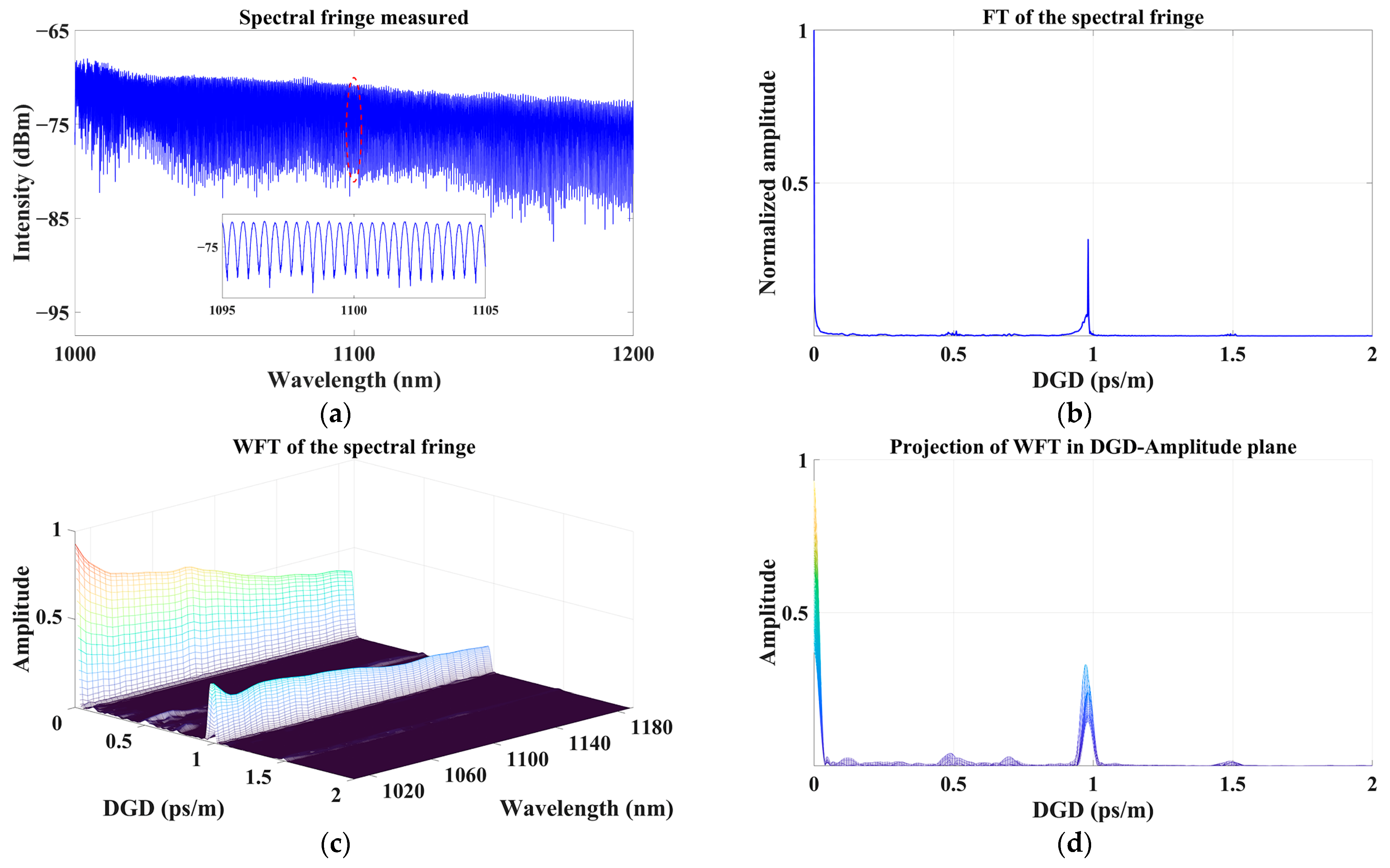
A 10 m commercial PMF (Nufern PLMA-GDF-25/250-M) was characterized in our experiment. A laser-driven light source (LDLS, ENERGETIQ EQ-99X) was used as the broadband source. We changed the initial condition so that almost the full fundamental mode (LP01 mode) was excited, and we measured the spectral fringe of a 200 nm wide spectral window (1000–1200 nm), which is shown in Figure 2a. The direct Fourier transform of the interference fringe is shown in Figure 2b. Then, we divided the fringe into several segments and windowed each segment using a Hann window (about 20 nm wide) with equal intervals (about 4 nm wide). Although the spectral fringes in this research were plotted with respect to wavelength, the Fourier transforms were taken with respect to frequency.
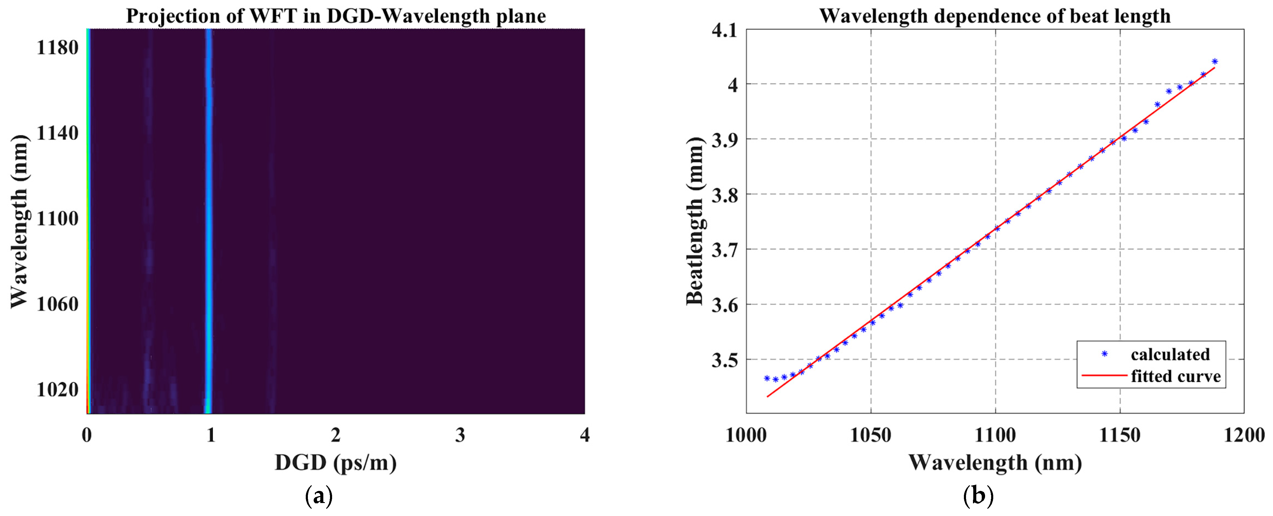
We created a spectrogram by stacking the Fourier transforms of these windows to form a three-dimensional mesh image to show the Fourier amplitude as a function of the DGD and the center wavelength of the window. Such a spectrogram (WFT) is shown in Figure 2c and its projection in the DGD-Amplitude plane is shown in Figure 2d, which accords with the FT result. The width of DGD peaks was different due to the variety of the number of sampling points. The DGD between the x-polarization and y-polarization state of LP01 mode was 0.99 ps/m, so the beat length of this PMF was 3.56 mm at 1060 nm from Equation (6). The beat length calculated by counting the periodicity of the interference spectrum in Figure 2a is 3.40 mm at 1060 nm, which is consistent with the results above. The projection of WFT in the DGD-Wavelength plane is shown in Figure 3a, from which we can discover that the DGD is almost independent of wavelength. Figure 3b shows the wavelength dependence of beat length, which accords with the theory that the beat length of PMF is nearly linear with the wavelength.

3.2. Characterization of Few-Mode Optical Fiber

An FMF (YOFC FM-SI-2) of 20 m length was measured, which has LP01 and LP11 at 1550 nm wavelength. At a wavelength near 1060 nm, the fiber allows four LP modes to exist. A super luminescent diode (SLD, THORLABS S5FC1050P) was used as the broadband source in the measurement.
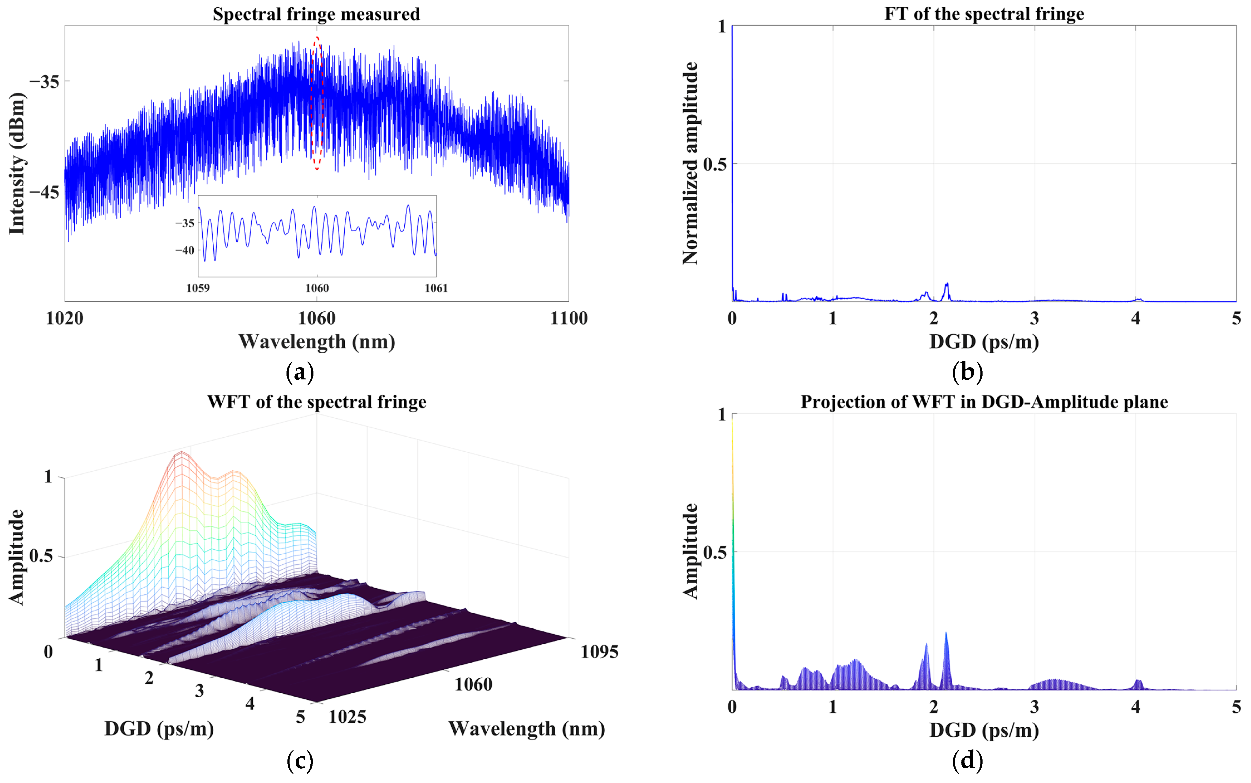
Under the condition that four LP modes were excited, we measured the spectral fringe of an 80 nm wide spectral window with a center wavelength of 1060 nm, which is shown in Figure 4a. The FT and WFT on the interference fringes are shown in Figure 4b–d. The projection of WFT in the Wavelength-Amplitude plane denotes the Fourier amplitude of modal interference, and it is in line with the fringe profile.
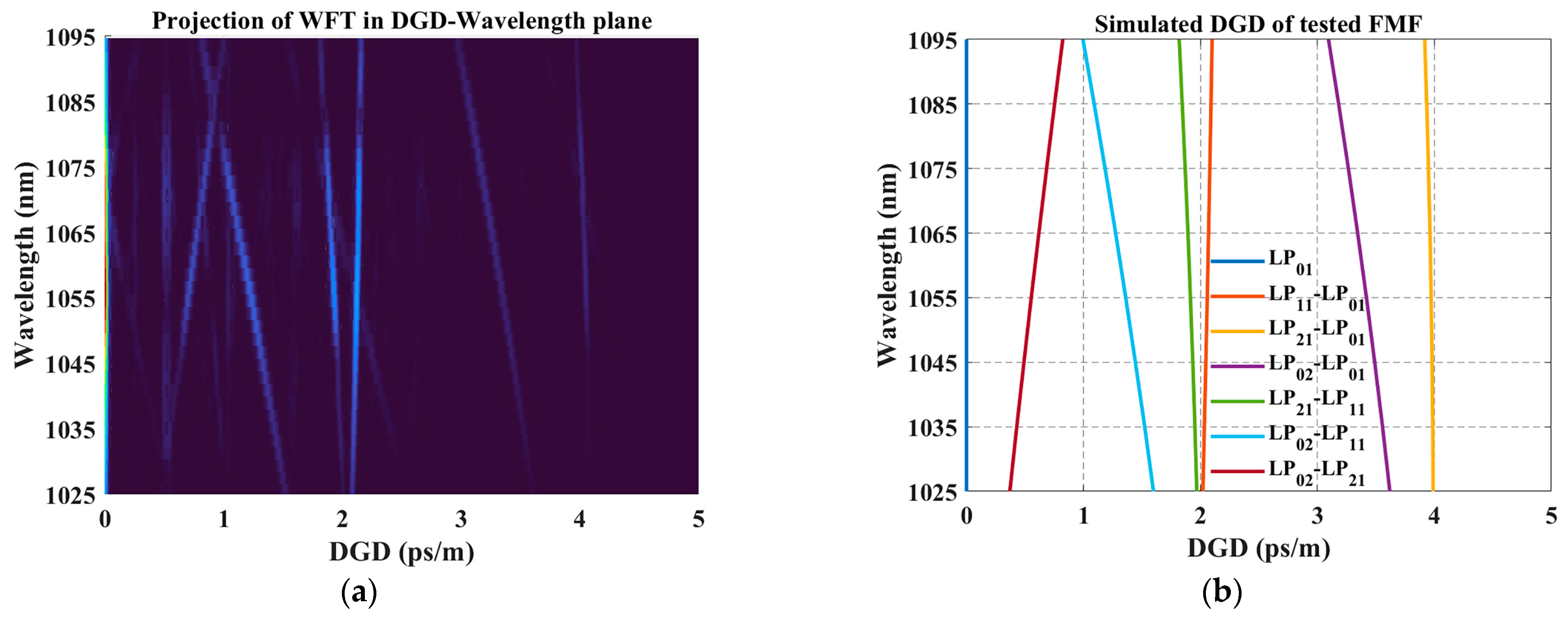
Various peaks are observed in the projection in Figure 4d. The peaks of the Fourier transform were distinguished by the dependence of DGD on the wavelength and the differential group dispersion obtained from Figure 5a, which shows the projection of WFT in DGD-Wavelength plane. Unexpected peaks appear at ~0.5 ps/m and its integral multiple, which is attributed to the reflections of core-guided modes from optical components within the setup [42]. These peaks were not introduced by modes propagating in the FUT because the group delay difference represented by these peaks was independent of the fiber length.
To verify the viability of this method and the accuracy of the measurement results, we numerically simulated the FMF using the COMSOL software. The refractive index distribution of the fiber was measured by Multiwavelength Optical Fiber Analyzer (Interfiber Analysis IFA-100, Sharon, MA, USA) to provide sufficient information for mode construction. We simulated effective refractive indices at different wavelengths for different LP modes by using the finite element method (FEM). The dispersion curves of LP modes were obtained by using interpolation, and thus their group refractive indices and the DGDs between all LP modes were calculated, and the results are plotted in Figure 5b. Comparing Figure 5a,b, the simulated results are basically consistent with the measured results, though there are slight differences in numerical value. For example, the measured differential group dispersion of LP11 was 1.07 ps / nm · km and the simulated result was 1.16 ps / nm · km . We attributed it to the uncertainty of the refractive index profile measurement of FUT and the inhomogeneous distribution in the angular and longitudinal directions.

4. Discussion

4.1. Noise Background of FT of Spectral Fringes

Due to the featured light source spectrum, the wavelength-dependent coupling efficiency of the mode, and random perturbation in the environment, the measured interference fringes always accompany a fluctuating envelope even in a short spectral window. Thus, the spectral background can lead to the rise of notable peak-like noise at small DGD.
We show a segment of the measured fringe in Figure 6a and normalized it by finding local maximums and minimums, shown in Figure 6b. The homogenized fringes give rise to one peak FT spectrum with a clean background where all noise peaks are eliminated.

4.2. DGD Peak Width

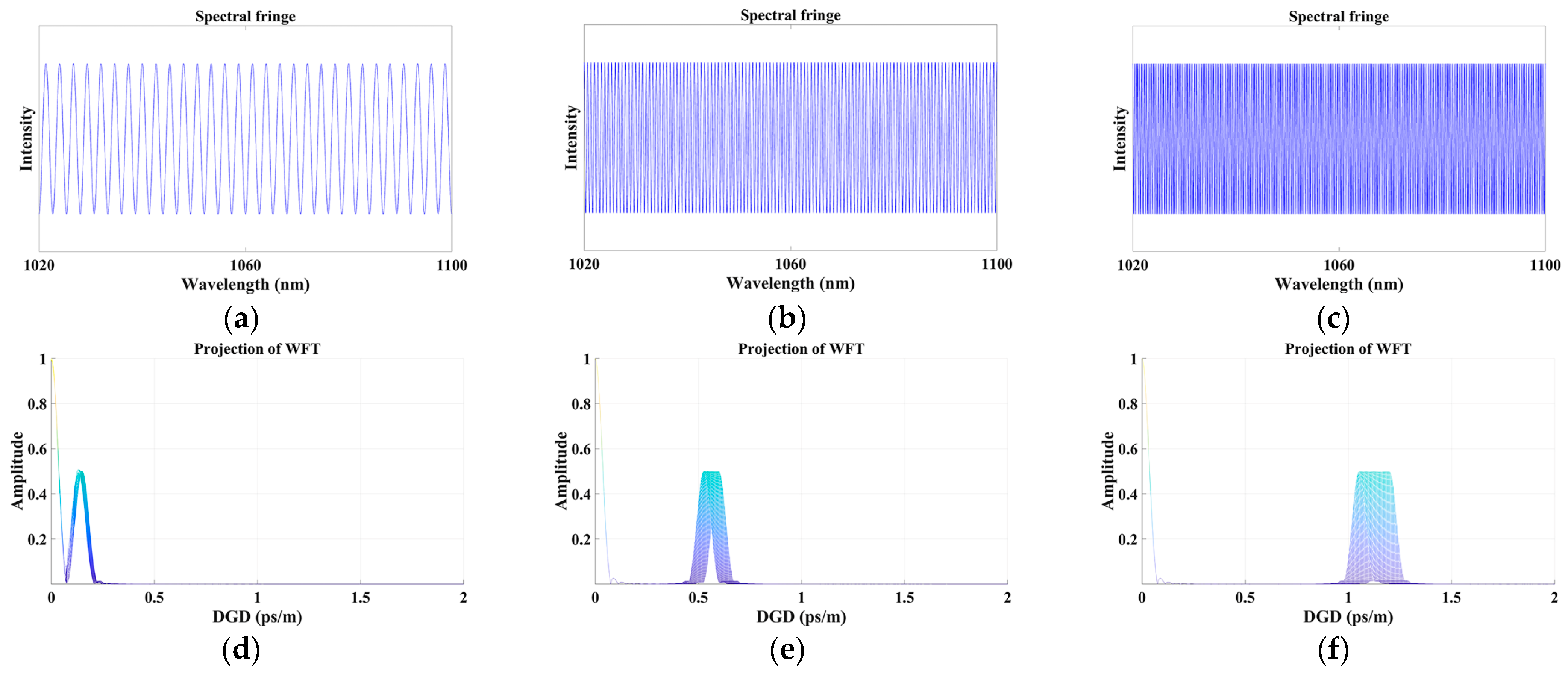
For a fixed amount of sampling points (20001 sampling points in the measurement of FMF), the width of the measured DGD peak is dependent on the dispersion of the differential modal group. As shown in Figure 4d and Figure 5a, the widths of all DGD peaks vary from the others which we attributed to the slope of DGD lines as a function of wavelengths. Obviously, the width of the DGD peak increases with the increase in the absolute value of differential group dispersion. We numerically simulated modal interference between two modes (LP01 and LP11 mode) with different differential group dispersion by using Equation (1) and the widths of DGD peaks obtained by our method as shown in Figure 7.

4.3. Error Induced in the Optical Path

The main errors of measurement are attributed to the partial reflection from optical elements in the optical path and the limited polarization extinction ratio of the incident light of FUT. Partial reflection at interfaces can be mostly eliminated by the anti-reflection coating. While the polarizer before FUT ensures the incidence of linear polarized light where the contribution of accumulated birefringence in the optical path to the measurement of FUT can also be suppressed.
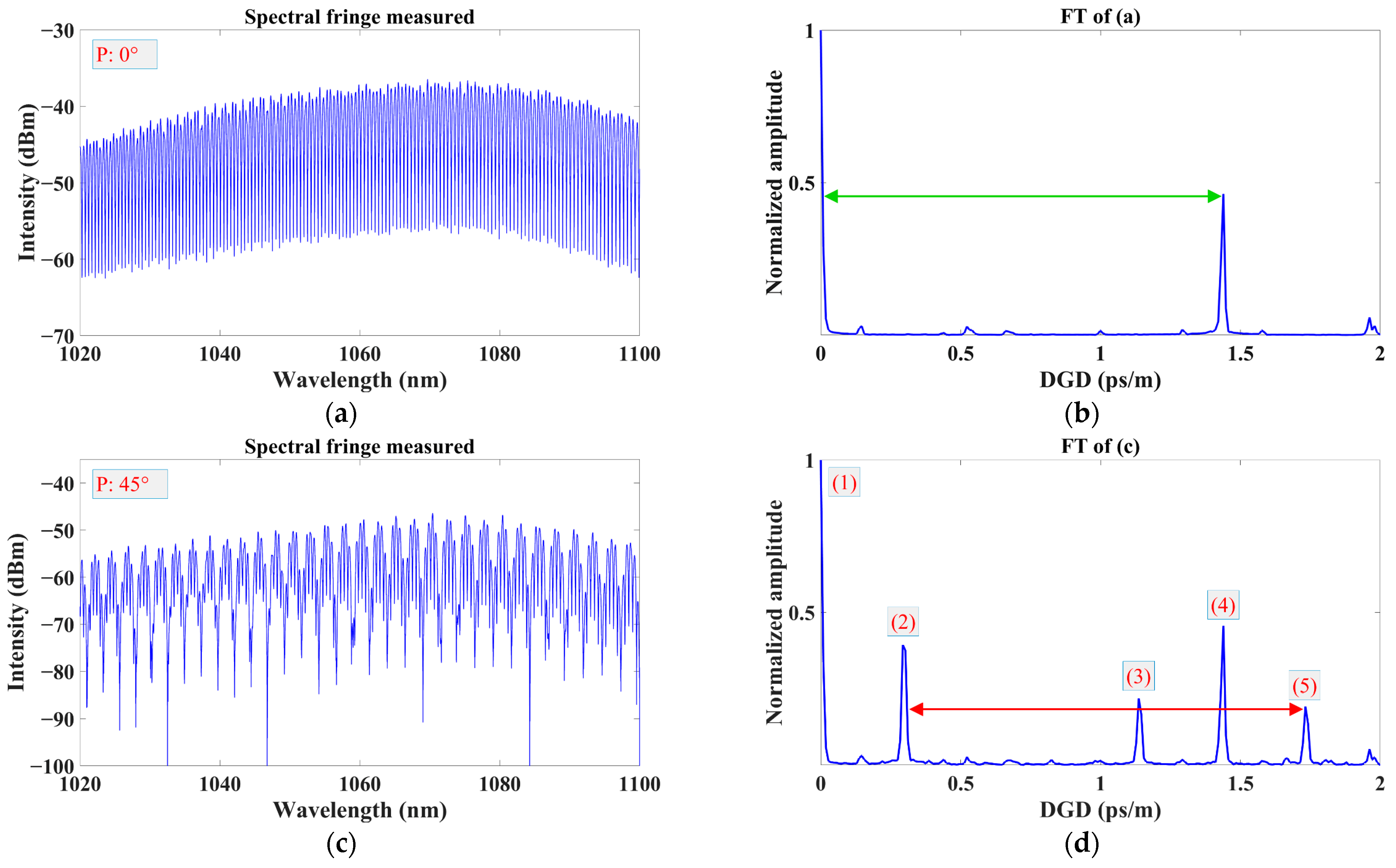
To illustrate, we used a 1 m single-mode PMF (COHERENT PM980) in the optical path to couple the output of SLD to a FUT (5.1-m PM980). The linear polarized light from SLD is incident at PM980 with the polarization direction paralleled at 45 degrees against the local slow axis. Polarizer P is rotated to control the incident polarization at the input end of FUT. The experimental setup is shown in Figure 8. The blue dashed arrows and red dashed arrows represent the fast axis direction of PM980 and the polarization direction of P, respectively. While the polarizer is aligned with the slow axis of PM980, the measured spectral fringe is shown in Figure 9a and the corresponding FT is shown in Figure 9b, which is similar to Figure 3. The birefringence of FUT is 4.32 × 10⁻⁴ (marked by the green arrow). While the polarizer is aligned by 45 degrees with a slow axis, the measured spectral fringe is shown in Figure 9c and the corresponding FT is shown in Figure 9d. Additional peaks appear in the FT plot. Peaks (2) and (5) originated from the birefringence of PM980 (4.32 × 10⁻⁴, marked by the red arrow) before FUT, namely, the birefringence in the optical path. Peak (3) is introduced by the interference between modes corresponding to peak (2) and peak (4).

5. Conclusions

A modified crossed polarizer technique method is proposed to characterize the differential group delay (DGD) of few-mode optical fiber (FMF). The modal interference at the output of FMF is analyzed by windowed Fourier transform (WFT). The dependence of DGD as a function of wavelength is obtained accordingly. We discussed the noise background, the width of DGD peaks, and possible errors introduced in the optical path in the modified crossed polarizer technique.

Author Contributions

Conceptualization, C.W., and F.Y.; methodology, C.W., F.Y., and S.F.; software, C.W.; validation, C.W.; formal analysis, C.W., and F.Y.; investigation, C.W., F.Y., and S.F.; resources, C.Y., and L.H.; data curation, C.W.; writing—original draft preparation, C.W.; writing—review and editing, F.Y., C.Y., L.X., and L.H.; visualization, C.W.; supervision, F.Y., and L.H.; project administration, F.Y., and L.H.; funding acquisition, C.Y., R.Z., and Z.J. All authors have read and agreed to the published version of the manuscript.

Funding

This research was funded by the National Key Research and Development Program of China (2020YFB1312802); Natural Science Foundation of Hebei Province (F2021203002); Chinese Academy of Sciences (Pioneer Hundred Talents Program, ZDBS-LY-JSC020); National Natural Science Foundation of China (61935002); Key R&D Program of Shandong Province (grant number 2021CXGC010202).

Institutional Review Board Statement

Not applicable.

Informed Consent Statement

Not applicable.

Data Availability Statement

Data underlying the results presented in this paper are available at http://doi.org/10.57760/sciencedb.07136 (accessed on 31 January 2023).

Acknowledgments

F. Yu is partially supported by the Pioneer Hundred Talents Program, Chinese Academy of Sciences.

Conflicts of Interest

The authors declare no conflict of interest.

References

  1. Li, G.F.; Bai, N.; Zhao, N.B.; Xia, C. Space-division multiplexing: The next frontier in optical communication. Adv. Opt. Photonics 2014, 6, 413–487. [Google Scholar] [CrossRef]
  2. Huang, H.; Milione, G.; Lavery, M.P.J.; Xie, G.D.; Ren, Y.X.; Cao, Y.W.; Ahmed, N.; Nguyen, T.A.; Nolan, D.A.; Li, M.J.; et al. Mode division multiplexing using an orbital angular momentum mode sorter and MIMO-DSP over a graded-index few-mode optical fibre. Sci. Rep. 2015, 5, 14931. [Google Scholar] [CrossRef] [PubMed]
  3. Rademacher, G.; Ryf, R.; Fontaine, N.K.; Chen, H.S.; Essiambre, R.J.; Puttnam, B.J.; Luis, R.S.; Awaji, Y.; Wada, N.; Gross, S.; et al. Long-Haul Transmission Over Few-Mode Fibers With Space-Division Multiplexing. J. Light. Technol. 2018, 36, 1382–1388. [Google Scholar] [CrossRef]
  4. Ryf, R.; Randel, S.; Gnauck, A.H.; Bolle, C.; Sierra, A.; Mumtaz, S.; Esmaeelpour, M.; Burrows, E.C.; Essiambre, R.J.; Winzer, P.J.; et al. Mode-Division Multiplexing Over 96 km of Few-Mode Fiber Using Coherent 6 x 6 MIMO Processing. J. Light. Technol. 2012, 30, 521–531. [Google Scholar] [CrossRef]
  5. Kubota, H.; Morioka, T. Few-mode optical fiber for mode-division multiplexing. Opt. Fiber Technol. 2011, 17, 490–494. [Google Scholar] [CrossRef]
  6. Ming-Jun, L.; Hoover, B.; Shenping, L.; Bickham, S.; Ten, S.; Ip, E.; Yue-Kai, H.; Mateo, E.; Yin, S.; Ting, W. Low delay and large effective area few-mode fibers for mode-division multiplexing. In Proceedings of the 2012 Opto-Electronics and Communications Conference (OECC) 2012, Busan, Republic of Korea, 2–6 July 2012; pp. 495–496. [Google Scholar] [CrossRef]
  7. Li, M.J.; Ip, E.; Huang, Y.K. Large effective area FMF with low DMGD. In Proceedings of the IEEE-Photonics-Society Summer Topical Meeting, IEEE, Waikoloa, HI, USA, 8–10 July 2013; p. 86. [Google Scholar]
  8. Zhang, H.; Zhao, J.; Yang, Z.Q.; Peng, G.J.; Di, Z.X. Low-DMGD, Large-Effective-Area and Low-Bending-Loss 12-LP-Mode Fiber for Mode-Division-Multiplexing. IEEE Photonics J. 2019, 11, 1–8. [Google Scholar] [CrossRef]
  9. Li, K.M.; Chen, X.; Hurley, J.; Stone, J.; Li, M.J. Measuring modal delays of few-mode fibers using frequency-domain method. Opt. Fiber Technol. 2021, 62, 102474. [Google Scholar] [CrossRef]
  10. Chen, X.; Hurley, J.E.; Stone, J.S.; Li, M.J. Chromatic Dispersion Measurements of Single-Mode Fibers, Polarization-Maintaining Fibers, and Few-Mode Fibers Using a Frequency Domain Method. Photonics 2023, 10, 215. [Google Scholar] [CrossRef]
  11. Chen, X.; Li, K.M.; Hurley, J.E.; Li, M.J. Differential mode delay and modal bandwidth measurements of multimode fibers using frequency-domain method. Opt. Fiber Technol. 2022, 72, 102998. [Google Scholar] [CrossRef]
  12. Cheng, J.; Pedersen, M.E.V.; Wang, K.; Xu, C.; Gruner-Nielsen, L.; Jakobsen, D. Time-domain multimode dispersion measurement in a higher-order-mode fiber. Opt. Lett. 2012, 37, 347–349. [Google Scholar] [CrossRef]
  13. Liu, F.; Hu, G.J.; Chen, W.C.; Chen, C.G.; Song, C.C.; Chen, J.K. Simultaneous Measurement of MDL and DMGD in FMFs by Analyzing the Rayleigh Backscattering Amplitudes. IEEE Photonics J. 2019, 11, 1–13. [Google Scholar] [CrossRef]
  14. Veronese, R.; Galtarossa, A.; Palmieri, L. Distributed Characterization of Few-Mode Fibers Based on Optical Frequency Domain Reflectometry. J. Light. Technol. 2020, 38, 4843–4849. [Google Scholar] [CrossRef]
  15. Dallachiesa, L.; Veronese, R.; Fontaine, N.; Mazur, M.; Chen, H.S.; Ryf, R.; Palmieri, L.; Bigot, M.; Sillard, P. Measurement of Propagation Constants of Graded Index Multi-mode Fiber Using Rayleigh Backscattered Light. In Proceedings of the Optical Fiber Communications Conference and Exhibition (OFC), IEEE, Electr Network, Washington, DC, USA, 6–11 June 2021. [Google Scholar]
  16. Hamel, P.; Jaouen, Y.; Gabet, R.; Ramachandran, S. Optical low-coherence reflectometry for complete chromatic dispersion characterization of few-mode fibers. Opt. Lett. 2007, 32, 1029–1031. [Google Scholar] [CrossRef]
  17. Gabet, R.; Le Cren, E.; Jin, C.; Gadonna, M.; Ung, B.; Sillard, P.; Nguyen, H.G.; Jaouen, Y.; Thual, M.; LaRochelle, S. Complete Dispersion Characterization of Few Mode Fibers by OLCI Technique. J. Light. Technol. 2015, 33, 1155–1160. [Google Scholar] [CrossRef]
  18. Olsson, B.E.; Karlsson, M.; Andrekson, P.A. Polarization mode dispersion measurement using a sagnac interferometer and a comparison with the fixed analyzer method. IEEE Photonics Technol. Lett. 1998, 10, 997–999. [Google Scholar] [CrossRef]
  19. Yang, Y.H.; Duan, W.Q.; Ye, M. High precision measurement technology for beat length of birefringence optical fiber. Meas. Sci. Technol. 2013, 24, 025201. [Google Scholar] [CrossRef]
  20. Ou, Z.; Lu, L.; Zhu, X.; Zheng, G.; Li, J.; Liu, Y.; Yue, H.; Dai, Z.; Zhang, L. The research on beat length of polarization maintaining optical fiber with external pressure. Optik 2014, 125, 6058–6062. [Google Scholar] [CrossRef]
  21. Poole, C.D.; Favin, D.L. Polarization-mode dispersion measurements based on transmission spectra through a polarizer. J. Light. Technol. 1994, 12, 917–929. [Google Scholar] [CrossRef]
  22. Jian, M.I.; Chunxi, Z.; Zheng, L.I.; Zhanjun, W.U. Measuring the Beatlength of Polarization Maintaining Fiber by Broadband Light Source and Conoscopic Interference. J. Optoelectron. Laser 2006, 17, 1074–1077. [Google Scholar]
  23. Nicholson, J.W.; Yablon, A.D.; Ramachandran, S.; Ghalmi, S. Spatially and spectrally resolved imaging of modal content in large-mode-area fibers. Opt. Express 2008, 16, 7233–7243. [Google Scholar] [CrossRef]
  24. Xu, Y.; Ren, G.B.; Jiang, Y.C.; Gao, Y.X.; Li, H.S.; Jin, W.X.; Wu, Y.; Shen, Y.; Jian, S.S. Bending effect characterization of individual higher-order modes in few-mode fibers. Opt. Lett. 2017, 42, 3343–3346. [Google Scholar] [CrossRef]
  25. Xu, J.S.; Zhao, J.; Xu, T.H. Modified S2 schemes for estimating differential mode group delay in polarization-maintaining few-mode fiber. Opt. Fiber Technol. 2022, 70, 102887. [Google Scholar] [CrossRef]
  26. Flavin, D.A.; McBride, R.; Jones, J.D.C. Dispersion of birefringence and differential group delay in polarization-maintaining fiber. Opt. Lett. 2002, 27, 1010–1012. [Google Scholar] [CrossRef] [PubMed]
  27. Tang, F.; Wang, X.Z.; Zhang, Y.; Jing, W. Characterization of birefringence dispersion in polarization-maintaining fibers by use of white-light interferometry. Appl. Opt. 2007, 46, 4073–4080. [Google Scholar] [CrossRef] [PubMed]
  28. Hlubina, P.; Martynkien, T.; Urbanczyk, W. Dispersion of group and phase modal birefringence in elliptical-core fiber measured by white-light spectral interferometry. Opt. Express 2003, 11, 2793–2798. [Google Scholar] [CrossRef] [PubMed]
  29. Hlubina, P. White-light spectral interferometry to measure intermodal dispersion in two-mode elliptical-core optical fibres. Opt. Commun. 2003, 218, 283–289. [Google Scholar] [CrossRef]
  30. Yin, W.H.; Huang, S.J.; Yan, C. Beat length measurement study of few-mode polarization-maintaining fiber based on low coherence off-axis digital holography. Opt. Commun. 2021, 484, 126695. [Google Scholar] [CrossRef]
  31. Jasapara, J.; Yablon, A.D. Spectrogram approach to S2 fiber mode analysis to distinguish between dispersion and distributed scattering. Opt. Lett. 2012, 37, 3906–3908. [Google Scholar] [CrossRef]
  32. Nicholson, J.W.; Meng, L.; Fini, J.M.; Windeler, R.S.; DeSantolo, A.; Monberg, E.; DiMarcello, F.; Dulashko, Y.; Hassan, M.; Ortiz, R. Measuring higher-order modes in a low-loss, hollow-core, photonic-bandgap fiber. Opt. Express 2012, 20, 20494–20505. [Google Scholar] [CrossRef]
  33. Inoue, M.; Ohashi, M.; Kubota, H.; Miyoshi, Y.; Shibata, N. Differential group delay measurements of few-mode fibers using an interferometric technique. IEICE Commun. Express 2020, 9, 330–335. [Google Scholar] [CrossRef]
  34. Yu, J.X.; Tan, F.Z.; Yu, C.Y. Few-Mode Fiber Characterization System Based on the Spatially and Spectrally Imaging Technique. Sensors 2022, 22, 1809. [Google Scholar] [CrossRef] [PubMed]
  35. Hlubina, P. Spectral-domain intermodal interference under general measurement conditions. Opt. Commun. 2002, 210, 225–232. [Google Scholar] [CrossRef]
  36. Dong, F.; Da, F.; Huang, H. Windowed Fourier Transform Profilometry Based on Advanced S-Transform. Acta Opt. Sin. 2012, 32, 0512008. [Google Scholar] [CrossRef]
  37. Kemao, Q. Windowed Fourier transform for fringe pattern analysis. Appl. Opt. 2004, 43, 2695–2702. [Google Scholar] [CrossRef] [PubMed]
  38. Noda, J.; Okamoto, K.; Sasaki, Y. Polarization-Maintaining Fibers and Their Applications. J. Light. Technol. 1986, 4, 1071–1089. [Google Scholar] [CrossRef]
  39. Chau, Y.F.; Yeh, H.H.; Tsai, D.P. Significantly enhanced Birefringence of photonic crystal fiber using rotational binary unit cell in fiber cladding. Jpn. J. Appl. Phys. Part 2—Lett. Express Lett. 2007, 46, L1048–L1051. [Google Scholar] [CrossRef]
  40. Chau, Y.F.; Liu, C.Y.; Yeh, H.H.; Tsai, D.P. A comparative study of high birefringence and low confinement loss photonic crystal fiber employing elliptical air holes in fiber cladding with tetragonal lattice. Prog. Electromagn. Res. B (USA) 2010, 22, 39–52. [Google Scholar] [CrossRef]
  41. Okamoto, K.; Edahiro, T.; Shibata, N. Polarization properties of single-polarization fibers. Opt. Lett. 1982, 7, 569–571. [Google Scholar] [CrossRef]
  42. Gray, D.R.; Sandoghchi, S.R.; Wheeler, N.V.; Baddela, N.K.; Jasion, G.T.; Petrovich, M.N.; Poletti, F.; Richardson, D.J. Accurate calibration of S2 and interferometry based multimode fiber characterization techniques. Opt. Express 2015, 23, 10540–10552. [Google Scholar] [CrossRef]
Figure 1. Experimental setup for spectral beating measurement. P: Polarizer. FUT: Fiber under test. A: Analyzer. SMF: Single-mode fiber. OSA: Optical spectrum analyzer. L1, L2, and L3: Lenses for coupling and collimating.
Photonics 10 00518 g001
Figure 2. Measurement results on a 10 m length of PLMA-GDF-25/250-M. (a) Spectral fringe measured. (b) FT of the spectral fringe. (c) WFT of the spectral fringe. (d) The projection of WFT in the DGD-Amplitude plane.
Photonics 10 00518 g002
Figure 3. Projection of WFT in DGD-Wavelength plane (a); the wavelength dependence of beat length (b).
Photonics 10 00518 g003
Figure 4. Measurement results on a 20 m length of YOFC FM-SI-2. (a) Spectral fringe measured. (b) FT of the spectral fringe. (c) WFT of the spectral fringe. (d) The projection of WFT in the DGD-Amplitude plane.
Photonics 10 00518 g004
Figure 5. Projection of WFT in DGD-Wavelength plane (a); simulated DGD of tested FMF (b).
Photonics 10 00518 g005
Figure 6. Fourier transforms of the original and homogenized spectral fringes. (a) Original spectral fringe. (b) Homogenized spectral fringe. (c) Fourier transforms of the spectral fringes.
Photonics 10 00518 g006
Figure 7. The relationship between the width of the DGD peak and the differential group dispersion. (ac) Simulated spectral fringes. (df) Projections of WFTs in DGD&Amplitude plane.
Photonics 10 00518 g007
Figure 8. Experimental setup. P: Polarizer. FUT: Fiber under test. A: Analyzer. SMF: Single-mode fiber. OSA: Optical spectrum analyzer. L1, L2, and L3: Lenses for coupling and collimating. Blue dashed arrows: The fast axis direction of PM980. Red dashed arrows: the polarization direction of P.
Photonics 10 00518 g008
Figure 9. The results of different incident polarization states. (a,b) The measured spectral fringe and the corresponding FT while the polarizer is aligned with the slow axis of PM980. (c,d) The measured spectral fringe and the corresponding FT while the polarizer is aligned by 45 degrees with the slow axis of PM980.
Photonics 10 00518 g009
Disclaimer/Publisher’s Note: The statements, opinions and data contained in all publications are solely those of the individual author(s) and contributor(s) and not of MDPI and/or the editor(s). MDPI and/or the editor(s) disclaim responsibility for any injury to people or property resulting from any ideas, methods, instructions or products referred to in the content.