1. Introduction
The electromagnetic radiation of the terahertz (THz) frequency range 0.3–10 THz attracts a lot of attention now due to its specific properties and promising applications in various scientific and technological fields. THz waves are non-ionizing, which is very important in biophotonics, medical and security systems [
1,
2], they pass without absorption through many dielectric packaging materials but demonstrate characteristic absorption lines in other important substances, which is very useful for non-invasive inspection and nondestructive testing systems [
3], and they are quite promising for future wireless communication links due to a high bandwidth potential [
4]. Among the various methods currently being developed to generate THz radiation, the approaches using pulsed optical lasers [
5] allow the most powerful (when pumping the nonlinear crystals [
6] or photoconductive antennas [
7]) and broadband (under laser-driven generation in the gas plasma [
8]) THz radiation within table-top systems to be obtained. The optical rectification (OR) of femtosecond laser pulses is known as one of the most widely applied methods. It is based on the effect of the generation of quasi-constant polarization during the passage of an intense optical beam through a nonlinear crystal, and the subsequent generation of freely propagating THz waves [
5,
6,
9].
Various materials, such as GaAs, GaSe, GaP, ZnTe, CdTe, organic crystals DAST and OH1, and others [
5,
9,
10,
11] are used to create laser-driven nonlinear optical effects. One of the best options for OR is to apply a lithium niobate crystal doped with magnesium (Mg:LiNbO
3), due to its high nonlinear susceptibility in the THz range and the possibility of manufacturing rather long crystal samples [
12,
13]. However, the condition of exact phase-matching can be satisfied only for the non-collinear interaction of the optical and THz waves in this crystal. The collinear process is possible under a quasi-phase matching condition within a narrow frequency band, but with the decreased working nonlinear coefficient of the periodically poled crystal [
14]. Two different approaches are currently applied to arrange the broadband non-collinear OR processes in Mg:LiNbO
3. The most famous one is based on the use of the pump beam with the tilted pulse front and the prism-shaped Mg:LiNbO
3 [
15]. The second approach uses the sideways Cherenkov generation scheme with a pump focused into a transversely limited volume in a crystal. To obtain the most radiation from the crystal, the sideways extraction schemes are commonly supplied by the special coupling prism adaptors [
12,
13,
16,
17,
18]. High-resistant silicon (Si) still remains as the best material choice for such prism adaptors due to its high transparency in the THz range [
19]. THz generation efficiencies achieved now by this method are slightly lower than the records of the tilted pulse front approach [
6], but the possible potential of the Cherenkov scheme is far from being exhausted.
A rather large amount of the THz radiation energy cannot be transmitted from the nonlinear crystal to the outer space without significant losses at the crystal and Si adaptor boundaries. This is due to the fact that the terahertz beam is initially generated inside the crystal with a large angular divergence, and the waves generated in the lateral directions experience significant or total internal reflection. Fundamentally, the high angular divergence takes place due to rather small dimensions of the pumped part of the nonlinear sample in comparison with the THz wavelengths. The divergence of the initially generated beam is noticeable, first of all, in the azimuthal angle, being determined by a limited cross-section of the laser beam [
20]. As a result, the part of THz radiation generated with the high transverse phase mismatch is not negligible in comparison with the part generated in phase-matched directions. Obviously, it cannot completely escape out of the crystal using the sideways geometry with a standard Si-prism coupler. Moreover, even if it escaped into the open space, the waves propagate in a very wide cone which cannot be fully focused further on either the object of study or on the detector.
We believe that some special shaping of the output surface of the Si adapter can increase the efficiency of the THz energy transfer in the Cherenkov scheme. Indeed, in a number of previously published papers, the high THz generation performance was demonstrated experimentally with Si-prism couplers with various convex output surfaces of spherical or semi-cone shapes [
21,
22,
23]. However, they did not present an idea of how such surfaces were chosen for design, and what surface parameters were generally decisive. The main goal of our work was to make calculations and find out what forms of the output surfaces were optimal for efficient THz generation. One possible approach for adequately modeling the involved processes could be based on directly solving the Maxwell equations in spatial variables, as was demonstrated previously in calculations of the spatial field distribution outside the Si-prism with the flat output surface [
24]. However, obtaining a detailed angular distribution of the THz power density both in the polar and azimuthal directions, taking into account crystal absorption at THz frequencies, the anisotropy of the crystal second-order susceptibility, and the arbitrary shape of the output Si-coupler surface, seems to be quite difficult with this method. In this paper, we develop another approach based on integrating the solutions of nonlinear wave equations for individual spatial modes [
25] of the focused pump and divergent THz radiation in the nonlinear crystal (
Section 2). Its application enabled the performance of a comparative study of the angular distributions of THz power density inside the Mg:LiNbO
3 crystal, inside the Si-coupler (
Section 3) and after passing the spherically shaped Si-coupler surface of the arbitrary convex parameter (
Section 4). Finally, we present results calculated for the total THz power, emitted within a detectable angle cone (
Section 5). They show that the efficiency of THz generation into the outer space through a convex Si-prism surface can be much more or less than in case of the flat output surface. It was found that the ratio between the lens curvature radius and the distance from the curvature center to the point of generation on the lens axis I s one of the main parameters responsible for the efficiency of THz generation from this point.
2. Modeling of THz Generation Inside a Nonlinear Crystal
The THz generation process under OR with femtosecond laser pulses can be considered as a continuous set of simultaneous nonlinear three-wave processes of parametric difference frequency generation (DFG) [
5]. In each DFG process, two different spectral components of the pump pulse, with frequencies
and
, generated a THz wave at frequency
with efficiency depending on the phase mismatch
between the corresponding wave vectors
,
, and
in the nonlinear crystal. Usually, the OR schemes are designed under the assumption that the pump beam contains only plane wave components with collinear
and
parallel to the direction of the pump beam (X axis in
Figure 1a), and the longitudinal projection of the phase mismatch on this direction
is equal to 0 for the generated THz waves [
5,
6,
9,
12,
13,
16,
17,
18]. Then, the longitudinal phase-matching condition
strictly implies the direction of the generated THz wave. However, the plane wave approximation was not valid for a variety of experimental schemes where the transverse dimensions of the focused pump beam were comparable with THz wavelengths. Due to the effects of spatial multi-mode pumping, the THz waves could be generated in other directions. For example, in case of the Gaussian pump beam profile at frequency
,
the spatial decomposition by plane waves (modes)
gives a continuum of amplitudes of partial modes:
with slightly different longitudinal projections and the transverse wave vector components
. In Equations (1) and (2),
is the pump beam waist and
describes the pump amplitude. The spatial pump harmonics given by Equation (2) can effectively interact with the corresponding spatial pump harmonics
at frequency
, thus generating THz waves in a continuum of directions. Usually, the transverse size of the crystal is greater than the pump beam waist. For each direction, the transverse phase-matching condition
should be satisfied for each three interacting plane waves.
For the analytical modeling of the angular distribution of THz radiation emitted inside the Mg:LiNbO
3 crystal at a fixed THz frequency, we used a general theoretical expression for one of the elements of the so-called crystal nonlinear scattering matrix [
25] which described the field transformation in a three-wave parametric process. Explicit forms for all the elements were obtained recently in [
26] within the low-gain approximation, but taking into account the multimode type of the three-frequency parametric process. The matrix element that is necessary for our further calculations describes the linear conversion of the field amplitude at
to the field amplitude at
in the presence of the pump wave at
with the spatially limited Gaussian profile:
Here,
stands for the spatial harmonic of the pump field with the wave vector transverse projection
; the polar (
) and azimuthal (
) angles are spherical coordinates of each wave vector
(
i = 1, 2, ”
THz”) inside the crystal, and
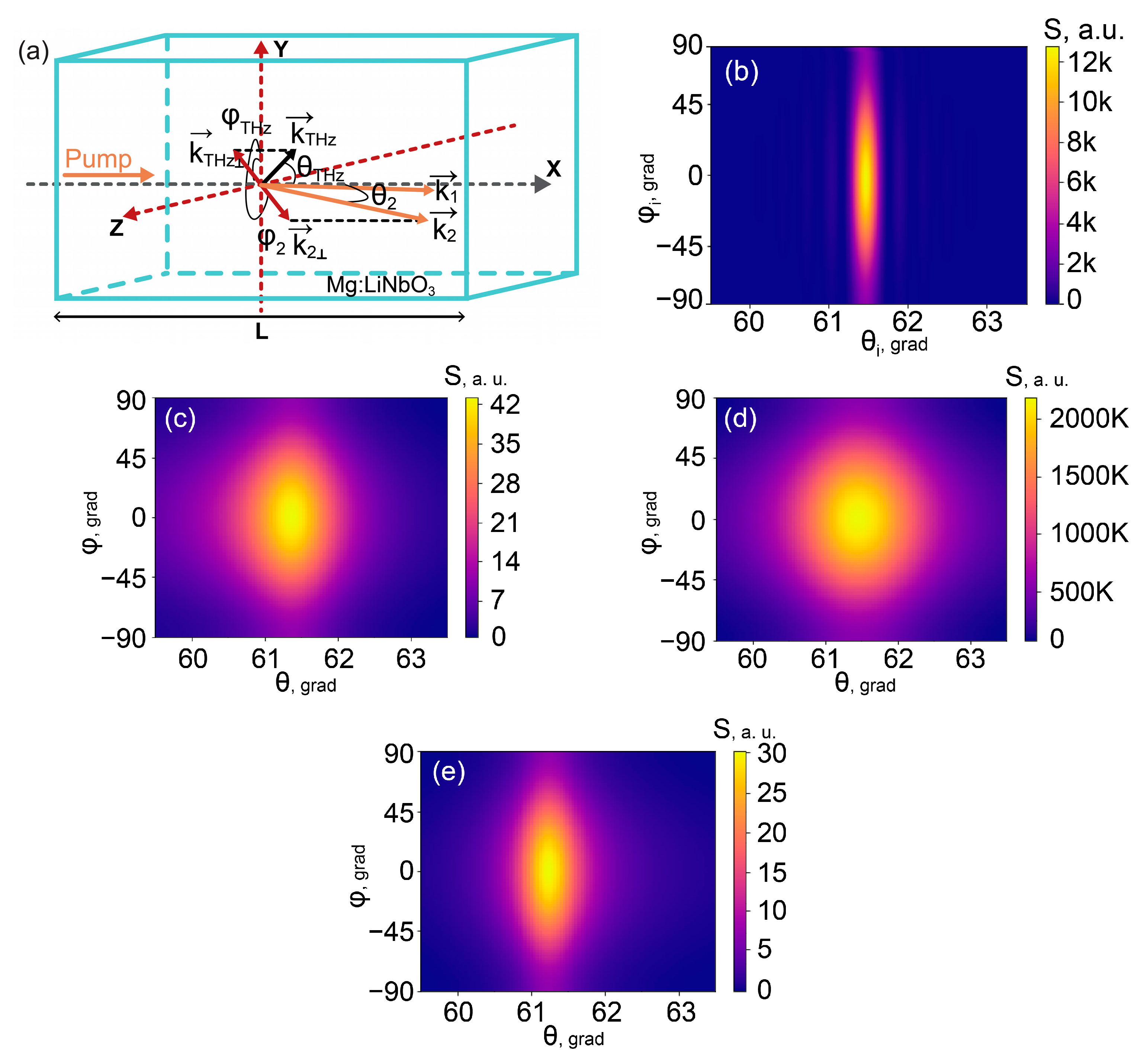
L is the crystal length. As shown in
Figure 1a, the polar angle
is measured from the pump beam direction (X axis), the azimuthal angle
is counted from the Y axis, and the polar crystal axis coincides with the Z axis. In the case of a nonlinear crystal with the same 3 m symmetry as Mg:LiNbO
3, all the three waves should be extraordinarily polarized along Z axis and propagate in the XOY plane (
,
) to obtain the majority of the crystal nonlinear susceptibility tensor components. However, when the azimuthal angle changes significantly, one has to take into account a decrease in the working Z-projection of the corresponding field. Equation (3) accounts for a convolution of the crystal second-order susceptibility tensor
with the polarization vectors of interacting waves in the form of
[
27].
accounts for the crystal intensity absorption coefficient
at THz frequency:
.
The scattering matrix element has to be multiplied by the amplitude
of the pump component at frequency
to produce the amplitude of the THz field generated in this elementary three-wave process. Finally, after integrating over all possible pump components at frequency
(
) and taking the modulus square of the obtained THz field, we obtain the expression for calculating the angular distribution of the THz power. Up to angular/frequency independent coefficients, it takes the form
The total power is connected with this angular power density as
[
26].
Figure 1b shows an example of the power density calculation for the case of THz generation at
= 1 THz. The data on the dispersion parameters of congruent lithium niobate crystal with 7.1 mol.% of Mg doping impurity were taken from [
28] for the visible range and from [
29] for THz range. Here, we assumed that
wp = 100 μm and did not take into account the crystal absorption,
= 0.
Figure 1c shows how this distribution changes if we take into account the intensity absorption coefficient
= 13 cm
−1. The width of the distribution along the polar angles increased, while the generation efficiency decreased substantially at all angles. The broadening of polar angles also took place in the case of the tighter focusing of the pump beam; see an example in
Figure 1d calculated for
wp = 5 μm and
= 13 cm
−1. However, the generation efficiency (the power density) was significantly increased due to the different physical nature of this effect. The first exponential multiplier in the integrand in Equation (4) was responsible for the degree of accomplishment of the transverse phase-matching; it was maximal at zero polar angles and became broader when
wp decreased. Other terms determined the longitudinal phase matching and described the observed generation maximum. Its center shifted to a non-zero angle
, and its width was mostly dependent on the crystal absorption and length, but the power density depended on how wide the wings of the first exponential multiplier were. Increasing
wp inevitably led to the decreasing of this multiplier at the generation angles. According to our calculations made for 1 THz and
= 13 cm
−1, when
wp = 150 μm the longitudinal phase matching maximum at
decreased to such extent that it became comparable with the weak transverse phase-matching maximum at
; the further increasing of
wp above 200 μm made the sideways generation maximum practically negligible.
Figure 1e shows the results for the lower frequency, 0.5 THz (
wp = 100 μm). The crystal absorption decreased at this frequency to
= 4 cm
−1. This led to narrowing of the generation line within the polar angle axis and to the increasing of the generation power at the phase-matching polar angle. However, the last effect was not as pronounced since the general coefficient
in Equation (4) was less by four times. Other parameters of the angular distribution, such as
and the shape of azimuthal distribution, practically did not change.
Next, we studied how the distribution shown in
Figure 1a, which was the narrowest of all presented in
Figure 1 for 1 THz, transformed after passing through the coupler to the outside.
3. Angular THz Power Density Distribution Inside the Si-Prism
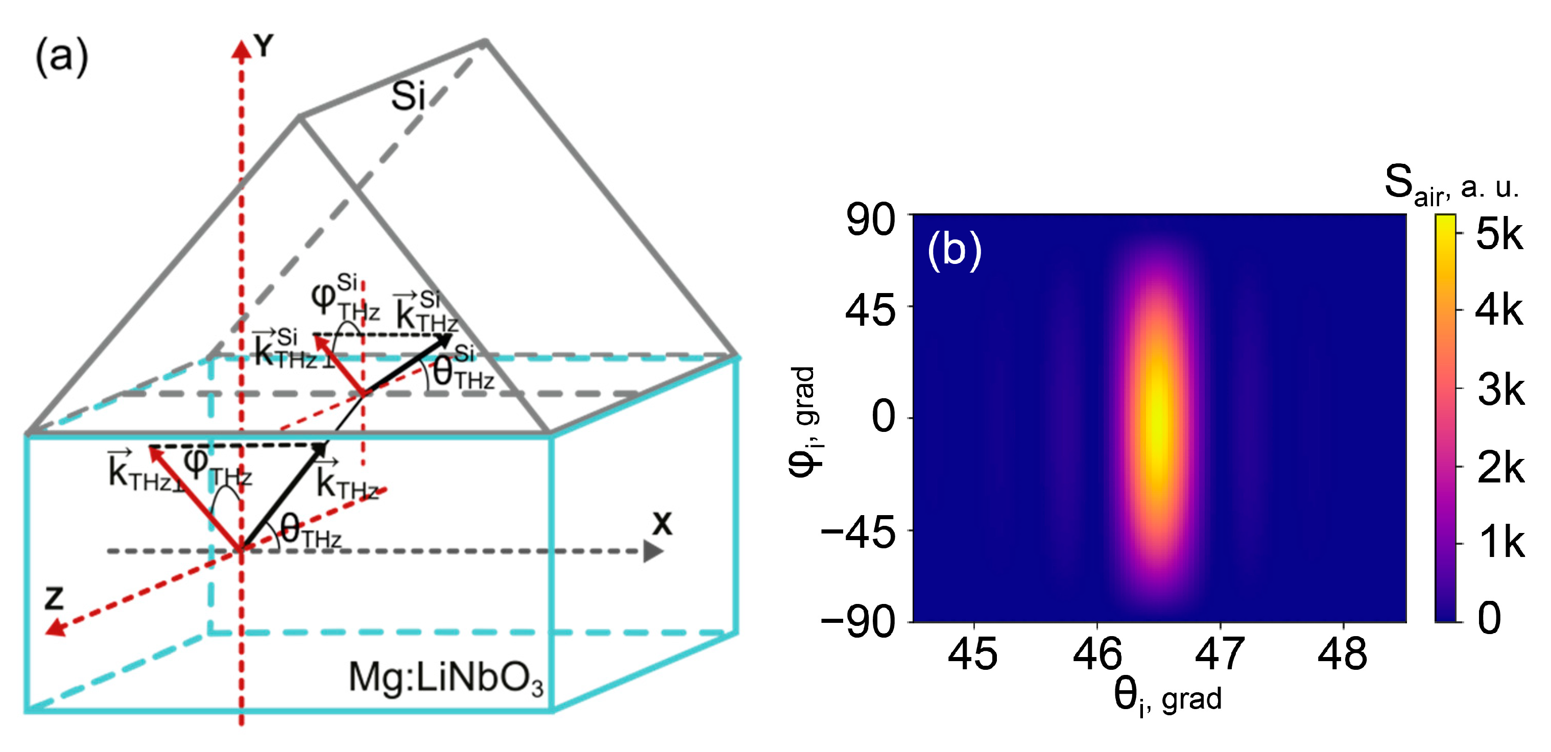
As it emerged from the crystal, the THz radiation hit the interface between the crystal side surface and Si-prism (
Figure 2a). After crossing the crystal/prism interface, the angular divergence of the beam changed significantly. According to the Snell’s law, we obtained the new azimuthal (
) and polar (
) angles of propagation inside Si:
Here,
and
are the refractive indices for THz waves in the nonlinear crystal (in our case, Mg:LiNbO
3) and high-resistive silicon, respectively.
Figure 2b shows how the initial angular divergence of the beam generated at 1 THz reshapes in the Si-prism. In our calculations, we used the data on
from [
30]. The angular dependence of the transmittance
at the crystal-Si interface was accounted by taking Fresnel coefficients for s-polarized and p-polarized THz waves, which were initially generated as extraordinary waves in the crystal. The angular density of THz radiation power in the prism
was calculated taking into account a change in the angular parameters upon transition to a new medium, according to
Comparing
Figure 1b and
Figure 2b, one can see how much the maximum of the power density decreases and how the angular divergence of the THz radiation increases when passing through the crystal–silicon interface. The angular divergence did not grow substantially, while the maximum power level decreased several times after transmission into Si. According to (6), two factors led to this decrease: the low value of the intensity transmission coefficient
(down to 0 when THz waves with high azimuth deviation do not escape from the crystal due to the total internal reflection), and some angular spread of the beam after its transmission through the boundary. The angular spread gave a decrease in the ratio
between the interconnected angular intervals in the crystal and Si-prism.
4. THz Power Density Distribution Outside the Si-Prism with a Flat or Spherical Output Surface
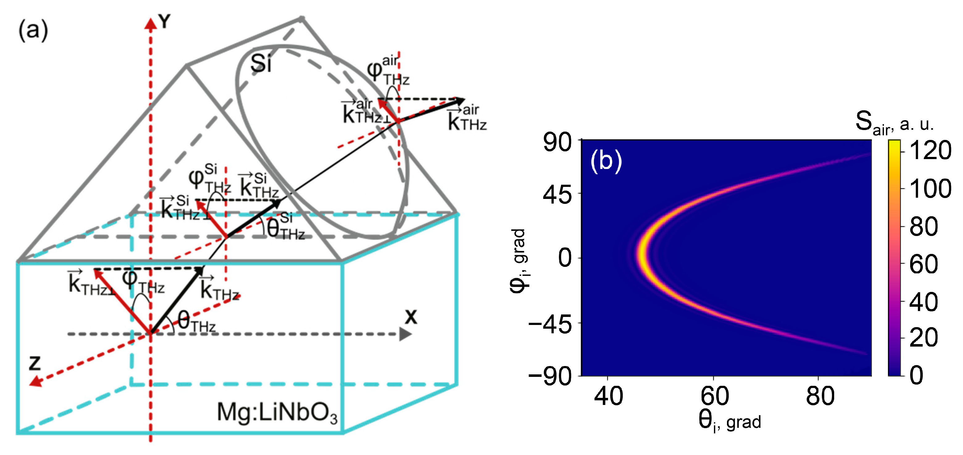
Now let us consider the angular distribution after the THz radiation exits the Si-prism (
Figure 3a). In most of the previous works on sideways THz generation in lithium niobate crystals, the output surface of the Si-prism was flat (the case of an output surface in
Figure 2a or without a plano-spherical lens in
Figure 3a). This surface is oriented at a normal angle for the propagation of the phase-matched part of THz beam, which is emitted in the crystal at the “phase-matched direction”, i.e., at
(equivalent to the opposite direction 180°) and
, satisfying the longitudinal phase-matching condition
taken at
. The phase-matching polar angle was calculated according to relation
, where
is the group velocity of the pump beam in a crystal. An output surface of the flat Si-prism should be cut at an angle
(
Figure 4). As follows from Equation (5), the directions of these phase-matched THz waves inside and outside the Si-prism are the same for a wide range of THz frequencies where the refractive index dispersion is negligible. However, the total angular divergence of the THz beam can be rather high after passing the interface between the plane output surface of the Si-prism and air. Moreover, the waves with high azimuthal deviation from the phase-matched direction
were emitted at polar angles that were noticeably larger than
. Presented in
Figure 3b are the results of our calculations of the angular power density
, which show that for different azimuth deviations
there can be found different polar angles
where the power density is maximal.
In this and subsequent calculations of the transmittance at the Si-air interface, a similar procedure was used as in the study of propagation through the crystal–Si interface. The direction of the wave polarization vector in the first medium was determined and then projected onto the plane of incidence (for p-polarized waves) or its normal (for s-polarized waves) to use the corresponding Fresnel transmittance coefficients. It was found that, in contrary to the case of the crystal–Si interface, the directions of wave propagation strongly rotated when the initial angles of generation deviated from the corresponding phase-matching angles.
As can be seen from a comparison between the color scales in
Figure 2b and
Figure 3b, the angular power density significantly decreased after the final transition outside the Si-prism. This effect was much more (by an order of magnitude) pronounced than the similar decrease under the transition from the crystal to the Si-prism. The reason is in the huge spread of polar directions of THz waves in the air. The range of admissible values of
started from almost the same small deviations from the phase-matched direction
at the low-angle side and up to 90° at high angles (
Figure 3b). In contrary to the propagation in crystal and Si, the polar directions of maximal THz power density in the air depended strongly on the azimuthal angle. As a result, the factor
and, correspondingly, the power density in the phase-matched direction, were strongly decreased. This effect may not be noticed if one does not consider the power density transformation, but solely the propagation of a single phase-matched plane wave and its transmission coefficient
. However, we intended to take into account more than the plane phase-matched wave, since the group of waves that diverges within a certain registration angle was usually important in the experiment. Thus, it is of value to study the transformation of the precise angular power density. The subsequent integration of the power density over a corresponding registration angle made it possible to predict the experimental results.
Therefore, our calculations showed that the power density measured in the optimal (longitudinally phase matched) direction decreased almost by ~100 times after propagation through a flat Si coupler. Mostly this took place due to the strong angular spread of the THz radiation. However, the angular divergence of the THz waves caused by propagation through the output surface of the Si element may be decreased if the surface was prepared with some specially adjusted curvature. At its simplest, this could be undertaken by the imposition of a plano-spherical Si lens on the flat surface of a prism (
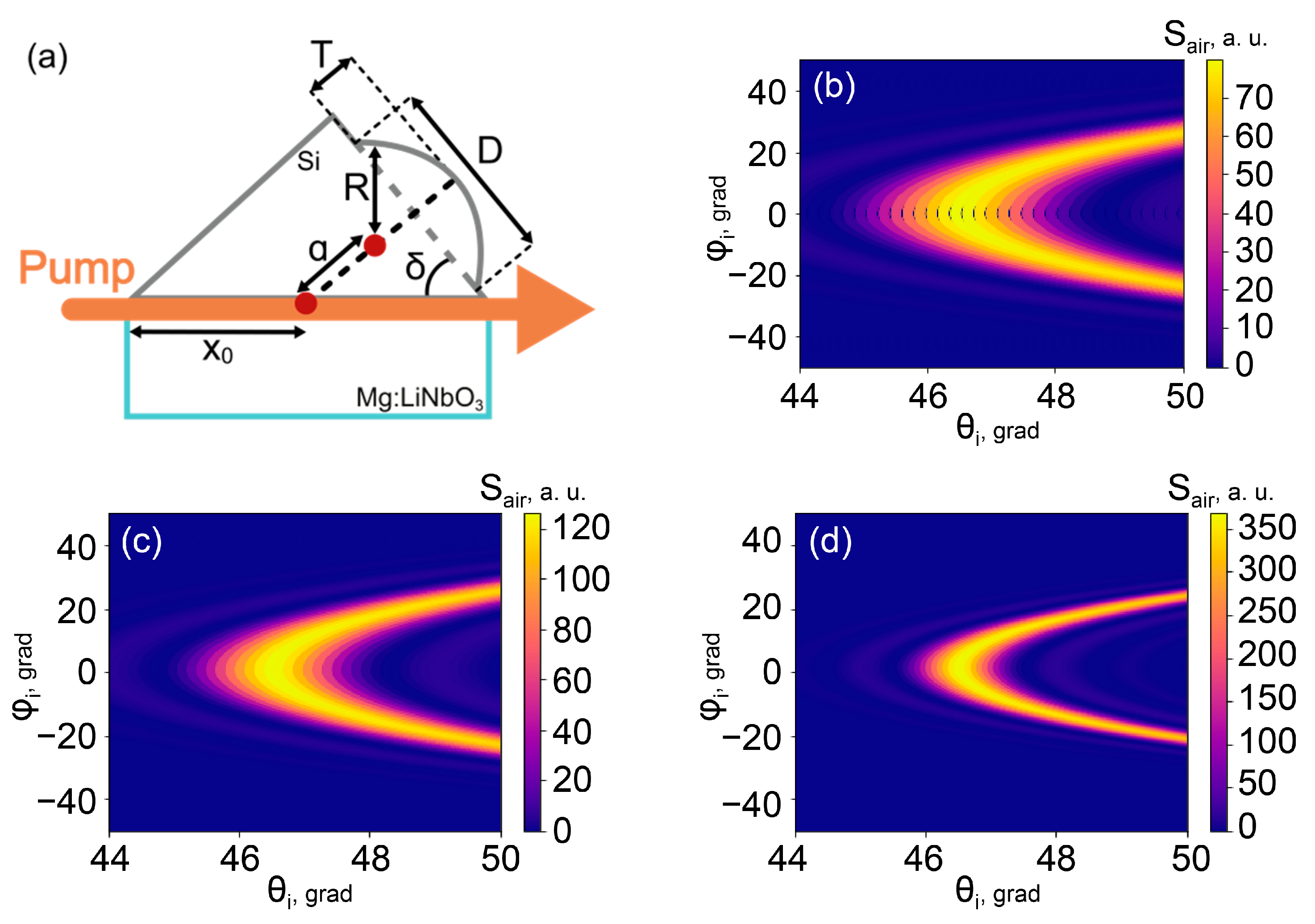
Figure 3a). The losses and distortions occurring due to a possible air gap at the lens/prism interface could be ignored since both elements are made from the same material and the gap width can be considered negligible in comparison with the THz wavelength. Therefore, the second and final transformation of the angular divergence took place at the lens-air interface. For simplicity, in our calculations we considered only the waves emitted in the crystal near the point with the coordinates
where the main lens axis intersected with the pump beam at the crystal side surface, as is shown in
Figure 4a. Since the azimuthal divergence was much greater than the polar one in crystal and Si materials, this approach can clarify the most important features of the angular distribution of THz intensity outside the lens surface. Here, we did not take into account the possible angular limitations due to the finite dimensions of the areas of the crystal–Si or Si–air boundaries, thereby analyzing the widest possible angular distributions. Thus, the point
was assumed to be located at such distance from the right corner of the prism that the waves emerging from this point could not pass through the lens surface only in the case of total internal reflection.
Made within this model, our calculations showed that the angular distribution of the THz intensity in the air was dependent on a single lens parameter
. Here,
was a radius of the lens surface curvature and
was a distance between the center of the lens spherical surface and the point of THz generation
. For example, the angle of incidence on the lens–air surface
for the THz wave propagating at the angles
was determined by the following relation:
Other parameters of the THz beam were related to by more complex analytical expressions.
The output angular distributions of radiation at 1 THz frequency were calculated numerically, taking different lens parameters.
Figure 4d demonstrates the working (suitable for subsequent detection) part of the distribution obtained for the case when a plano-convex lens with
= 0.68 was imposed on the flat exit surface of the Si-prism.
Figure 4b corresponds to the case when the lens parameter is much greater:
= 1.2. For comparison, the distribution when there is no lens is also given on the same scale in
Figure 4c. This case of a flat prism corresponds to an intermediate value of the lens parameter
. As can be seen from
Figure 4, the use of the lens with
= 1.2 led to some unwanted increases of the polar divergence of the output THz beam and to the decrease of the distribution maximum in comparison with the flat prism. However, the use of the lens with the smaller parameter
= 0.68 provided a significant collimation of the output beam and, correspondingly, a substantial increase of the distribution maximum.
Our calculations made for 1 THz showed that the shape of the curve
in the angular distributions of the power density outside the Si-prism clearly depended on the value of the curvature parameter
. Its curvature
(taken at any fixed points, for example, at the phase-matching angles) gradually decreased to 0 when the value of
went down to
. A further decrease of
led to an increasing bend of an opposite sign (
Figure 5b). At
the bend disappeared, and
stood the same for all azimuthal angles
and, as inside a Si-prism,
. For any chosen shape of the output Si-prism surface, the power density achieved its maximum at the phase-matching polar and azimuthal angles. However, for different convex parameters of the output surface, the value of this maximum grew when
approached
and the curvature module
decreased.
5. Comparison of Si Couplers with Different Convex Output Surfaces
To compare Si-prism couplers with different convex output surfaces, we have focused on calculating the total THz power that can be detected under experimental conditions within some reasonable angular apertures at a certain THz frequency. The theoretical distributions of the angular power density, obtained for different lens parameter
, were integrated over realistic intervals
,
.
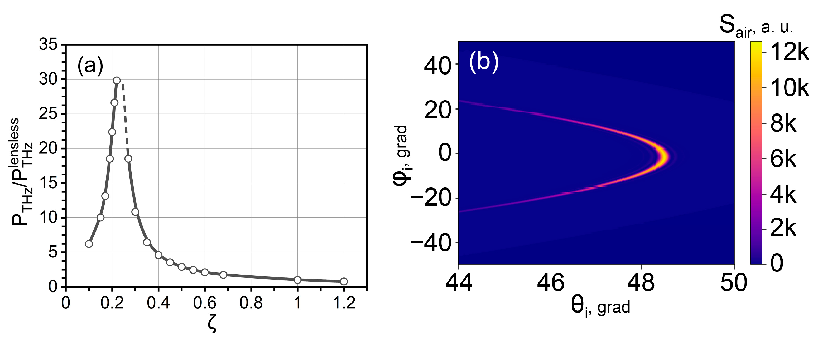
Figure 5a shows how the integral power
at 1 THz varied with the lens parameter
. The power data were scaled using the power
corresponding to the standard flat prism surface with
= 1. The main tendencies followed from the results on the angle power density: the use of the lens surface with
< 1 was better than in the case of the flat, lensless prism. There should be some optimal value near
, where the emitted power is maximal. The line
, which connects the points of the most efficient generation in the angular distribution, was not curved at
. The maximum of the emitted power density happened at the same polar angle for any azimuthal direction, just as it occurred inside the crystal (
Figure 1b) or inside the Si-prism (
Figure 2b).
Figure 5b shows how the angular distribution flips to the other side in comparison to
Figure 3 and
Figure 4 when the lens parameter decreases below
.
Generally, the presence of a well pronounced maximum in the theoretical dependence in
Figure 5a indicates that there should be some optimal value of the surface curvature radius
R for each emitting point in the crystal, located at its distance
from the center of curvature. This result shows the way for further improvements of the final THz generation efficiency in the sideways geometry. Since
depends linearly on the distance
x from the beginning of the crystal, the use of the output surface of Si-prism with a conical type of curvature should be preferable to the considered simplest approach with an easily accessible lens. A consistent study of this possibility will be an interesting continuation of this work.


