Abstract
Breast cancer is a leading cause of cancer-related deaths in women, and treatment involved invasive surgery such as lumpectomy. In the last decade, a non-invasive, non-contact high-intensity focused ultrasound (HIFU) therapy was developed for treatment with promising results. However, its success rate depends on patient selection, tissue heterogeneities, HIFU operational parameters, and even imaging techniques. In this emerging field, computer simulations can provide us with a much-needed platform to learn, test, and deduce results virtually before conducting experiments. In this study, we used three different classes of anatomically realistic numerical breast phantoms from clinical contrast-enhanced magnetic resonance imaging (MRI) data, including scattered-, heterogeneous-, and extremely dense-type breasts. Upon assigning the appropriate acoustic and optical parameters to the tissues within, we simulated HIFU propagation by using the k-Wave toolbox in MATLAB and compared the changes introduced in the three types of breasts. It was found that scattered-type breast was best-suited for HIFU therapy. Furthermore, we simulated light-beam propagation with the ValoMC toolbox in MATLAB after introducing the lesion to compare the distribution of the initial pressure generated via the photoacoustic effect. This simulation study will be of significant clinical impact, especially in the study and management of HIFU-based treatments, which are individual/tissue-selective in nature.
1. Introduction
Breast cancer is the leading cause of cancer in women. According to statistics, of all cancer diagnoses among women occur from this deadly disease [1]. Breast cancer occurs when essential genes mutate in the breast, leading to uncontrolled cell growth [2]. Several genetic and environmental features also influence such mutations and tumour mass growth. In this regard, early detection and efficient treatment can play a crucial role in reducing the mortality rate caused by this deadly disease. Presently, mammography and ultrasonography are routinely used in clinics as screening methods [3,4]. Both modalities deliver morphological information about the underlying tissue. Recently, breast-conserving surgery combined with adjuvant therapies has been the standard early-stage therapeutic approach, which has been shown to be equally effective as mastectomy [5,6]. Breast surgeons normally use oncoplastic technique to decrease the impact of the local tumour excision on cosmesis. Various factors have been encountered that produce negative cosmesis consequences, such as being overweight, having tiny or very large breasts, developing a tumour in the lower quadrant of the breast, and having a large breast tumour [7]. Many therapeutic modalities are utilised to treat cancerous breast tissue, such as chemotherapy, radiotherapy, and hormone therapy [8]. Sometimes, these methods increase the harmful surgical impact due to tissue injuries, such as shrinking, fibrosis, and breast deformity. These are also non-invasive in nature. A variety of minimally invasive ablation techniques, such as radiofrequency ablation, cryoablation, and microwave ablation, have been introduced as alternatives to the state-of-the-art techniques [9,10,11]. All these techniques have promising attributes with improved cosmetic outcomes and mortality. However, the percutaneous insertion of a probe is required for all these methods [12,13]. Therefore, there is a clinical need for an entirely non-invasive ablative treatment for the betterment of medical science.
High-intensity focused ultrasound (HIFU) is non-invasive thermal ablation that has been employed as an effective and safe treatment in many biomedical applications, such as bone metastases [14], uterine fibroma [15], liver tumours [16,17], and pancreatic tumours [18], among others. In HIFU therapy, a high-intensity ultrasound beam emitted from a specially designed (high-intensity) transducer is focused onto a particular tissue region [19,20]. The sharply focused acoustic energy is transformed into thermal energy, which leads to tissue coagulation or ablation in that specific tissue region without damaging the surrounding tissue [21]. These advantageous features are an excellent therapeutic pathway for breast cancer treatment. In past studies, it has been shown that, compared with lumpectomy, HIFU has potentially improved cosmetic outcomes, prevented scarring possibilities, and reduced postoperative recovery time. In addition, the risk of surgical complications is eliminated due to the non-invasive nature of the therapy. However, the shape, size, and location of the tissue ablation depend on the acoustic properties and structure of tissues within the breast, along with the acoustic parameters of the HIFU. The success rate of HIFU ablation also depends on tissue heterogeneities, imaging techniques, the ablation protocol, and patient selection [22].
HIFU-induced breast tissue coagulation is traditionally monitored by X-ray mammography [23]. However, it has decreased sensitivity in dense breast tissue. As an alternative, magnetic resonance imaging (MRI) has good sensitivity and specificity in dense breast tissue [24]. However, it carries the burden of high cost and processing time. Moreover, MRI requires an external contrast agent, which may lead to an allergic reaction in the central nervous system, as well as renal damage in some cases. Ultrasound imaging, on the other hand, is cost-effective and radiation-free but has low contrast and sensitivity towards the coagulated region [25]. Thus, a new imaging method that is not affected by breast density while overcoming the limitations mentioned above is demanded. Recently, photoacoustic (PA) imaging has attracted considerable attention in breast imaging applications [26,27]. It is an emerging modality that offers deep tissue imaging with rich optical contrast and scalable spatial resolution that is much higher than that of any purely optical imaging modalities [28,29]. Additionally, PA imaging enables the quantification of functional parameters (haemoglobin concentration and oxygen saturation) of breast tissue during cancer treatment [30].
Numerical simulation can be a useful tool to learn about all the above aspects. In the present study, we simulated acoustic and optical propagation inside a numerical breast phantom by employing the k-Wave [31] and ValoMC toolboxes [32] in MATLAB [33]. This simulation will be helpful for the optimal arrangement of HIFU with respect to an individual’s breast structural composition. Identification of suitable HIFU operational parameters via simulations performed here will greatly aid in the success of HIFU therapy. To this end, we used anatomically realistic numerical breast phantoms obtained from clinical contrast-enhanced magnetic resonance (MR) imaging data [34]. We then used the k-Wave toolbox to virtually simulate HIFU propagation. The simulations, being specific to a patient’s breast structure and composition, can be highly effective in deciding the operational parameters.
There have been many reported studies of HIFU simulation in breasts. Here, we extend this technique by comparing the effect of HIFU on three different types of breasts based on the density and distribution of fibroglandular tissue and discuss the potential consequences of the results obtained if carried out in the real world. We further simulated light-beam propagation after introducing lesions to compare initial pressure distributions due to the photoacoustic effect in the three breast types. This will be of great impact on photoacoustic imaging and the reconstruction of lesions in our future works.
2. Materials and Methods
2.1. Numerical Breast Phantom
The breast models (corresponding to free-hanging position) were reproduced from a publicly available online resource—the ‘Optical and Acoustic Breast Phantom Database (OA-Breast)’ [34,35]. Typically, these are contrast-enhanced MR data from healthy patients where contrast agents are injected to provide higher contrast for blood vessels and other structures. The MR data were then processed and segmented into four different tissue types: skin layer, blood vessels, fat, and fibroglandular tissue. Readers can refer to the sources cited above for details. Three sample types of breasts are classified as scattered fibroglandular, heterogeneously dense-, and extremely dense-type breasts. By assigning specific tissue optical and acoustic properties for each tissue type within the breast, we can generate a numerical breast phantom. The voxel size of all three sample breast phantoms is 0.2 mm. The loaded digital phantoms have a resolution of 0.2 mm as well. The 2D cross sections used for HIFU simulations have the same resolution in all three samples. In our study, a 2D model was used. Figure 1 shows a 2D cross-section of the extremely dense breast sample extracted from the 3D (mean) projected breast. The dimensions of the breast are 615 × 752 × 495 pixels (2D cross-section dimensions: 615 × 752 pixels, for an effective physical size of breasts of 12.3 cm × 15.04 cm). The cross-section was chosen roughly at the midpoint of the breast along the z-axis. Values used for acoustic, thermal, and optical properties in the simulation are shown in Table 1, Table 2 and Table 3. The region surrounding the breast (the black region in Figure 1) corresponds to water that serves as an acoustic coupling medium.
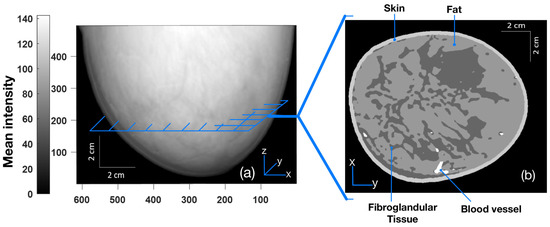
Figure 1.
(a) Three-dimensional mean projected breast (projected on the xz plane with pixel values corresponding to the skin, fat, fibroglandular, and blood vessels of 204, 153, 102, and 255, respectively, on the scale of 0–255). (b) Two-dimensional cross-section image (parallel to the xy plane) taken roughly from the midpoint of the breast [34,35].

Table 1.
Acoustic parameters corresponding to various parts of breast tissues (skin, blood vessels, fat, and glands) and the surrounding water employed in simulation for HIFU wave propagation [36].
Table 2.
Thermodynamic parameters corresponding to various parts of breast tissues used for simulation of heat deposition, diffusion, and the subsequent calculation of lesion area [36].
Table 3.
Optical parameters used for simulation of light propagation for initial pressure distribution via photoacoustic effect [35].
2.2. Ultrasound Propagation
Each transducer in HIFU is a source of sinusoidally propagating ultrasonic waves (at higher intensity) to the target tissue medium via a coupling medium (water in our case). Mathematically, we can write the wave equation governing the propagation of acoustic waves as [37]:
where p and are the pressure and ultrasound speed, respectively. Acoustic waves are sensitive to reflection, transmission, and refraction at an acoustically varying tissue–tissue interface. Because of this mismatch in acoustic parameters, a fraction of the acoustic wave energy is reflected at every tissue interface, while the remaining energy is concentrated at the HIFU focal point inside the tissues. In this way, ultrasonic waves undergo attenuation while propagating through a mechanical medium. In contrast to the case of fluids, the acoustic wave equation for tissue media obeying a power law for pressure attenuation is governed by the causal wave equation (which differs from Equation (1) above). It is fundamentally derived from the fractional constitutive equation between stress and strain [38]. The attenuation coefficient (), which is defined as (where is the absorption coefficient and is the scattering coefficient), provides a measure of the loss of acoustic energy in a medium as it propagates. Following a power law (as is the case of tissues), the attenuation coefficient in terms of ultrasonic frequency is expressed as [39]:
where a and b are constants, and f is the ultrasound frequency. Presuming attenuation is constant over a distance (x), the pressure amplitude decays exponentially with the distance traversed by the wave as a result of these attenuations, as expressed by [39]:
where and are acoustic pressures at two points inside the tissue separated by a distance of (x) along the direction of wave propagation. As a result, the acoustic (harmonic plane) wave solution is altered [39]:
where is the pressure at , and .
For the simulation corresponding to HIFU, we used k-Wave [31], which is an open-source MATLAB toolbox, for the time-domain simulation of acoustic wave fields. A snapshot of the simulation of acoustic wave propagation overlayed on the cross-section of an extremely dense-type breast is shown in Figure 2a, along with the distribution map of mass density (Figure 2b) and the acoustic attenuation coefficient (Figure 2c). The frequency was fixed at 1 MHz throughout the simulation studies, and the HIFU was focused approximately at the same distance from the skin tissue in all three breast samples to maintain uniformity. In Figure 2 for the case of an extremely dense-type breast, the simulation area was 92.25 × 112.8 mm with a pixel size of 0.2 mm × 0.2 mm. A HIFU arc length of 51 mm with a radius of 40 mm was simulated by a number of point pressure sources (∼339 with a pressure amplitude of 0.7 MPa) arranged uniformly on an arc.
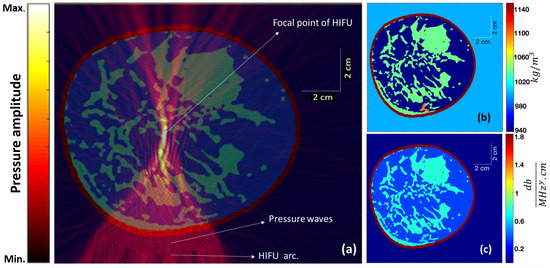
Figure 2.
(a) The steady-state instantaneous pressure wave amplitude (from the HIFU) overlayed on the cross-section of an extremely dense breast. (b) The mass density distribution map and (c) the acoustic attenuation coefficient map corresponding to different tissue structures within the cross-section.
2.3. Heat Deposition and Diffusion
The lost energy from ultrasound attenuation gives rise to local heating within the soft tissue [39]. The rate of heat deposition () is [40]:
where is Nepers per length, and P is pressure amplitude. The deposited heat is not localised with time because of heat diffusion through thermal conductivity (as well as blood perfusion). The transient heat transfer equation provides a general equation controlling thermal dynamics within tissues, and it can be written as [39]:
where k, C, and T are thermal conductivity, specific heat, and absolute temperature, respectively. This is basically an energy conservation statement, where is the net heat deposition rate per unit volume; is the thermal diffusion term; accounts for vasodilation and perfusion, which serves as a sink (cooling source); and Q is the heating source (from HIFU). Upon neglecting the cooling term in Equation (6) and using Equation (5), we obtain:
In order to non-invasively and non-destructively ascertain the heat deposition and temperature rise from HIFU, we used the above equation for numerical simulation. In this way, we adopted Equation (5) for numerical simulation of the rate of heat deposition using the k-Wave toolbox. The thermodynamic parameters adopted for this part of the simulation are shown in Table 2.
2.4. Thermal Dose and Lesion Formation
In order to access thermal tissue damage during heat deposition, one must determine the thermal dose received by the tissue. A unit called cumulative equivalent minutes () is commonly used to convert various time–temperature exposure profiles in experiments into an equivalent exposure time expressed in minutes with a reference temperature of 43 °C [41]. Mathematically, it is expressed as:
where for , for , and T is the temperature in °C.
In a wide range of tissues, regions with generally result in permanent ablation. We consider tissue regions with to be the area of the lesion in our current k-wave simulation studies. Due to heat diffusion in a medium, the lesion typically progresses from the focal point of the HIFU on-time. In the k-wave simulation, the lesion area was considered an area of grid points where equalled or exceeded 240.
2.5. Initial Pressure Rise in PA Imaging
The phenomenon of the generation of an acoustic signal resulting from the tissue’s rapid heating brought out by the transient illumination and absorption of a ∼nanosecond pulse of electromagnetic radiation is referred to as the photoacoustic (PA) effect. The lesion provides excellent contrast in the reconstructed PA image due to the contrast in the distribution of the lesion’s optical absorption coefficient with respect to the surrounding normal tissue. The rapid heating caused by transient electromagnetic wave irradiation can be seen as a perturbation of the thermodynamic equilibrium [28], since the tissue system is completely characterized by pressure (), volume (), and temperature (). Therefore, we can consider the tissue system to be a hydrostatic thermodynamic system. The initial pressure wave (initial photoacoustic signal, ) is related to the local temperature rise () at the lesion site that is caused by a short laser pulse and can be expressed as [28]:
where is the volume expansibility, and is the isothermal compressibility. Using the thermodynamic heat transfer relation for the absorbed heat density () and assuming that the optical energy absorbed by the tissue is completely converted into heat energy so that , we have
where and are specific heat capacity at constant volume and optical fluence, respectively [28], and is a tissue-specific constant at a particular temperature known as the Grueneisen parameter. The tissue medium then acquires this initial pressure distribution, which is represented by .
We employed ValoMC [32], a Monte Sarlo software (MATLAB toolbox), to simulate the transport of visible and near-infrared-range photons in biological tissue to simulate the photoacoustic effect and induce an initial pressure rise distribution. All the optical parameters used are shown in Table 3. The Gruneisen parameter was kept constant at 0.02. A Gaussian beam with a diameter of 30 mm and a standard deviation of was employed. The beam direction is shown in Figure 3a, as indicated by the red arrows from the bottom. The absorbed optical energy density was calculated by taking the product of optical fluence () and the optical absorption coefficient () at each point. Finally, the initial pressure rise was calculated by taking the product of the Gruneisen parameter and the calculated optical energy density. Note the exceptional visibility of the blood vessels in the initial pressure rise distribution map (Figure 3b) resulting from a very high relative value (hundreds of orders higher than the other included tissues) of the absorption coefficient () for the vessels.
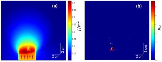
Figure 3.
(a) Optical fluence distribution in the medium. Red arrows suggest the incident light beam direction. (b) The initial pressure rise distribution.
2.6. Reconstruction
An assortment of acoustic sensors acquires the initial PA waves () upon exiting the tissue boundary. These boundary-collected data are used to reconstruct PA images using a variety of reconstruction methods. In the simulation study, a simple delay-and-sum (DAS)-based beamforming algorithm was used for the reconstruction of internal pressure distribution () resulting from transient illumination. As shown in Figure 4a, was acquired by a linear array transducer shown by a white line at the bottom. Figure 4a is the same as Figure 3b, except that the color range was squeezed to bring out more details. Figure 4b shows the corresponding reconstructed image. The sampling frequency was 33.33 MHz.
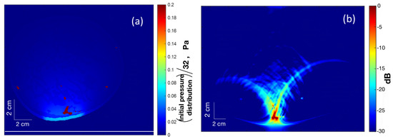
Figure 4.
(a) Map of (squeezed color range) the initial pressure distribution () with a linear array transducer at the bottom (white line) for PA reconstruction. (b) The reconstructed PA image.
3. Results
The simulation results of HIFU focused on three different types of breast (extremely dense, heterogeneously dense, and scattered fibroglandular) are shown in Figure 5. Our aim here is to determine how precisely the ultrasound waves from the HIFU are focused at its focal point. To this end, all the parameters of HIFU, such as arc length, radius, etc., were kept identical for all three breast types (except for HIFU position and tilt so as to have the freedom to align with varying shapes or sizes of breasts). The distance between the HIFU arc and the skin tissue was also kept the same for all breast types. The HIFU parameters are the same as those described in Section 2.2. The first column (Figure 5a–j) corresponds to the extremely dense-type breast, the middle column (Figure 5b–k) corresponds to heterogeneously dense-type breast, and the last column (Figure 5c–l) corresponds to scattered fibroglandular-type breast. The top row (Figure 5a–c) shows the distribution of HIFU pressure wave amplitude overlayed on the respective breast type. As can be seen, it is maximum for scattered-type breast at the focal point of HIFU, where the pressure waves are sharply focused. The second row (Figure 5d–f) shows the distribution of the heat deposition rate per unit area. Due to the relatively high presence of fibroglandular tissue in the focal zone in the case of heterogeneously dense breast, the heat deposition rate is maximum among the three breast types (see Section 4 related to Figure 6). The third row (Figure 5g–i) shows the lesion map overlayed on the respective breast type. It is interesting to note that despite the varying structures of tissues within, the distance from the centre of lesions to the HIFU arc came out to be the same for all three breast samples. The bottom row (Figure 5j–l) shows the initial pressure () distribution using ValoMC for the induced lesion. For this, the blood vessels were suppressed, as they have optical absorption coefficients hundreds of orders of magnitude higher than that of the surrounding breast tissue, resulting in high pressure at those sites.
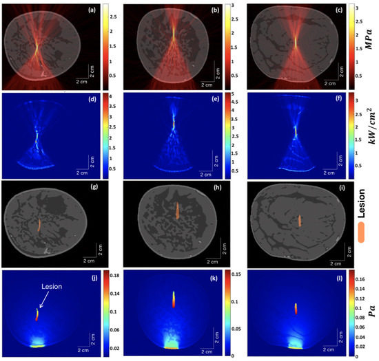
Figure 5.
The first column (a–j) corresponds to the extremely dense-type breast, the middle column (b–k) corresponds to the heterogeneously dense-type breast, and the last column (c–l) corresponds to the scattered fibroglandular-type breast. The top row (a–c) shows the distribution of HIFU pressure wave amplitude overlayed on the respective breast type. The second row (d–f) shows the distribution of the heat deposition rate per unit area. The third row (g–i) shows the lesion map overlayed on the respective breast type. The bottom row (j–l) shows the initial pressure () distribution for the induced lesion using ValoMC.
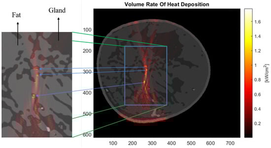
Figure 6.
Distribution map of the heat deposition rate per unit area for the extremely dense-type breast. The zoomed-in copy cutout shows that the rate peaks in the fibroglandular tissues present in the vicinity of the focal region of the HIFU.
Figure 6 shows the distribution of the heat deposition rate in the extremely dense-type breast. Upon close analysis of the heat deposition distribution and the overlayed breast image, we can see that the rate peaks in the fibroglandular tissue if it happens to be in the vicinity of the focal zone of the HIFU.
The variation of lesion area (area with ) with HIFU on-time for the three different types of breast is shown in Figure 7. Again, the HIFU parameters were kept the same, as described in Section 2.2 while increasing the HIFU on-time. Figure 8 shows a graph demonstrating the temperature increase exactly at the focal point of HIFU within the breast with HIFU on-time (5 s) and off-time (60 s). The temperature was measured at time steps of 0.1 s. This was done for all three samples. The peak temperature for the scattered-type breast came out to be the maximum among all, as expected, because of the obtainable sharp focusing (thus, more HIFU fluency) at the focal point compared to the other two samples.
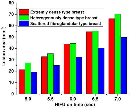
Figure 7.
Variation of lesion area (area with ) with HIFU on-time.
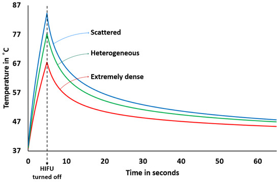
Figure 8.
Variation of temperature at the focal point of HIFU with HIFU on-time (for 5 s) and off-time (for a minute). The starting temperature was 37 °C.
4. Discussion
HIFU can be a viable, safe, effective, and non-invasive therapy for the treatment of localized breast cancer without any serious negative side effects [42]. Here, a 2D simulation for light- and acoustic-field propagation was carried out on three sample types of contrast-enhanced MR breast—scattered, heterogeneously dense, and extremely dense type (Figure 1). After incorporating the distribution of various required physical properties (Figure 2), the simulation for the HIFU field was carried out. The resulting thermal dynamics with lesions generation are discussed in Figure 9 and Figure 10. The initial pressure distribution determined via photoacoustic effect was also simulated (Figure 3). The results show that although breasts are made up of soft tissues, the complex structures within them do not show the propagation of acoustic waves similar to those of other soft (homogeneous) tissues. Our numerical simulation showed that scattered-type breasts can benefit most from HIFU therapy.
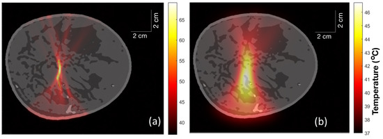
Figure 9.
(a) Temperature distribution within the extremely dense breast just after HIFU was turned on for 5 s. (b) Temperature distribution in the extremely dense breast 1 min after turning on the HIFU for 5 s.
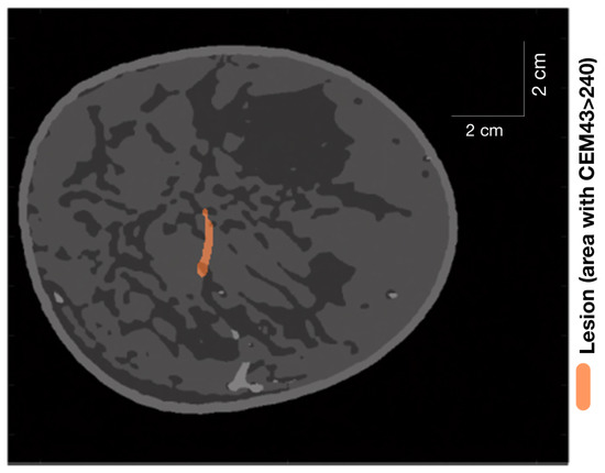
Figure 10.
Lesion (area with ) generated in an extremely dense breast after turning on HIFU for 5 s and then turning it off for 1 min.
From Figure 5d–f, we can infer that the denser the structure of fibroglandular tissue within the breast, the less sharply the ultrasound is focused at the focal point of the HIFU. Ideally, the lesion should have been elliptical in shape [43]. The deviation from the ideal behaviour is due to attenuation and scattering of focused ultrasound as it propagates through the breast, where it encounters fat and glands with different acoustic properties, which are distributed non-uniformly inside the breast. This imposes a defocusing challenge for HIFU therapy. Thus, HIFU is less precise for extremely dense breasts, as can be seen in Figure 5d. Our results are in agreement with those reported in [44], in which researchers studied a way to reduce defocusing by focus control based on the time-reversal method.
The initial pressure distribution shown in Figure 5j–l was carried out using the ValoMC MATLAB toolbox [32] to simulate photon transport within the tissue. The direction of the Gaussian beam is evident from the bottom, where intensity is high. The blood vessels were masked by the properties of fat tissue for this particular case to explicitly study pressure distribution at the lesions. The lesion areas were given a value of optical absorption coefficient 0.5 cm higher than that of fat [45]. As expected, the magnitude of pressure falls as we move along the propagation path of the light beam. The pressure magnitude at the focal point (lesion centres) for scattered fibroglandular breasts is higher than that of heterogeneous and extremely dense-type breasts. However, because of an extended lesion area due to defocusing in extremely dense breasts, the tip of the lesion comes closer to the direction of the light source, which results in a higher magnitude of pressure in that part. Thus, tumours or lesions can be detected relatively easily in scattered fibroglandular-type breasts.
The map of heat deposition rate per unit area (Figure 6) hints at yet another problem we might encounter while performing HIFU therapy. Parts of the fibroglandular tissue that are in the vicinity of the focal point of HIFU where the heating is to be performed acquire a locally higher rate of heat deposition. The reason can be traced to the acoustic attenuation coefficient relative to the surrounding fat tissue. Depending on the size and location of the tumour, this can pose an issue of potentially harming healthy glands in the vicinity of the HIFU focal point. This may not pose much concern in the case of scattered fibroglandular-type breasts, where the HIFU focal point can be sharply focused with little intervening fibroglandular tissue structure. So far, we have not found any source, either simulation or experimental, to verify this specific result. This can be a subject for future studies.
Finally, an investigation into the development of lesion area and temperature with HIFU on-time was carried out. This study demonstrates (see Figure 7) that we can assume that the lesion area grows fairly linearly over a time scale of a few seconds depending on the HIFU operational parameters. This is in agreement with lesion imaging experiments carried out in soft tissues and reported in Ref. [46]. For the given HIFU parameters and on-time, the scattered-type breast is observed to have a lower rate of increase in lesion area compared to extremely or heterogeneously dense breasts. This may be because of the presence of fibroglandular tissues in the vicinity of the focal point of the HIFU in the latter two samples, where the temperature peaks sharply (thereby essentially spreading the lesion centres), as discussed in the preceding paragraph. The relationship between lesion size and HIFU exposure time is not strictly linear for high-intensity and long time scales. While longer exposure times generally result in larger lesions, the relationship is complex and depends on several factors, including the intensity and frequency of the ultrasound waves, as well as the tissue type and properties. In general, there is a threshold exposure time below which HIFU treatment may not result in a visible lesion. Beyond this threshold, lesion size tends to increase with exposure time. However, there may be diminishing returns beyond a certain exposure time, as tissue may become more resistant to HIFU-induced thermal damage. Additionally, lesion size may not increase linearly with exposure time in all cases. Factors such as tissue heterogeneity, blood flow, and tissue perfusion can affect the ability of HIFU to induce tissue damage and may result in non-linear relationships between exposure time and lesion size. For a theoretical prediction of the size of a thermal lesion in soft tissue during HIFU treatment, see [47]. There have also been integrations of external controllers to achieve preferred and linearly varying predictable lesion sizes. For an experimental work in which the temperature was controlled to achieve the same, see [48]. Figure 8 shows the temperature increment and decrement at the focal point with HIFU on-time (5 s) and off-time (1 min). These trends are also in line with experimental (phantom) results (see Ref. [49]) and numerical simulation [50] for homogeneous soft tissues. The expected temperature at the focal point of scattered-type breast at any time is observed to be higher than for the other two types due to sharp focusing. Due to limited availability of hardware resources in our lab, experimental validation studies were not performed in the present work. We reserve this as an aim for our future research studies.
This shows that acoustic inhomogeneity plays a central role in the effectiveness of HIFU therapy in breasts. An optimal arrangement with respect to an individual’s structural composition of breast and identification of suitable HIFU operational parameters via a simulation such as this will greatly aid in achieving the goal. From the perspective of practical (realistic) applications in the present study, one can obtain a 3D map of the patient’s breast from a quality imaging modality (such as MRI) and then load it in a simulation software to virtually simulate HIFU therapy as in the present study. Such simulations, being specific to a patient’s breast structure and composition, can be of great impact in deciding the HIFU operational parameters and their alignment. In future works, we plan to incorporate the reconstruction of initial pressure distribution for photoacoustic imaging to monitor HIFU therapy in real time. The reconstruction of such lesions inside the breasts, along with intervening acoustic inhomogeneity, would require an advanced beamforming algorithm to have some correlation with lesion shape and size instead of a simple DAS beamforming algorithm (see Figure 4b for the sake of completion). The inclusion of machine learning will a great aid on this front.
The study presented in this article is not limited and can be further improved by incorporating several other aspects. In conventional simulations, the tissue parameters are kept constant for predictions, as in the present study. However, accounting for the change in the acoustic absorption coefficient due to changing temperature at the focal point leads to higher focal zone temperature variation and larger lesion sizes [43]. On the other hand, the incorporation of blood perfusion will serve as a sink for thermal energy at the focal zone, thereby reducing the focal zone temperature change and therefore the lesion size. Another aspect to take into account, which is more like a challenge, is the possibility of acoustic cavitation in the focal zone. Vapour bubbles could be induced if the temperatures at the focal zone approach the boiling point. This leads to enhanced heating and contributes significantly to induced hypothermia [51]. It is interesting to note that, as we have shown here, temperature may have a sharp peak in fibroglandular tissue if it lies in the vicinity of the focal point of HIFU; consequently, these sites can be more susceptible to bubble formation. There is also an effect on the magnitude of initial pressure distribution (from the photoacoustic effect) over the lesion created by HIFU. Both the optical absorption coefficient and reduced scattering coefficient increase in the lesion area compared to native tissue [45,52]. Better segmentation of breast tissue structures with more accurate values of their physical properties will obviously enable an overall improvement.
5. Conclusions
In this study, we simulated HIFU therapy by employing a MATLAB-based k-Wave toolbox and generated initial pressure distribution from the photoacoustic effect using the ValoMC toolbox. Both the open-source numerical tools—k-Wave and the ValoMC—were integrated together in MATLAB for the processing of three different numerical breast phantoms—extremely dense, heterogeneous, and scattered fibroglandular-type breast—along with the details of theoretical (analytical) formulation. We discussed the implications of the results and the associated challenges for HIFU therapy. We concluded that scattered fibroglandular-type breasts are well-suited for HIFU therapy and even for imaging of lesions or tumours due to their low acoustic inhomogeneity. Further improvements in the simulation can be achieved by incorporating dynamic tissue property variables with changing temperature and performing the simulation in 3D. Employing a better segmented numerical breast phantom, along with appropriate sources for acoustic and optical property values, will increase the reliability of the simulation. In the future, we plan to perform experimental validation studies and incorporate machine learning for the reconstruction of initial pressure distribution for photoacoustic imaging to monitor breast HIFU therapy in real-time.
Author Contributions
Conceptualization, S.P. and S.K.Y.; methodology, S.K.Y., S.P. and M.S.S.; software, S.K.Y.; validation, S.K.Y. and S.P.; formal analysis, S.K.Y. and S.P.; resources, S.K.Y.; writing—original draft preparation, S.K.Y., S.P. and M.S.S.; writing—review and editing, S.P. and M.S.S.; visualization, S.P. and S.K.Y.; supervision, M.S.S. All authors have read and agreed to the published version of the manuscript.
Funding
This research received no external funding.
Institutional Review Board Statement
Not applicable.
Informed Consent Statement
Not applicable.
Data Availability Statement
Not applicable.
Conflicts of Interest
The authors have no financial interest or conflict of interest to disclose.
References
- Sung, H.; Ferlay, J.; Siegel, R.L.; Laversanne, M.; Soerjomataram, I.; Jemal, A.; Bray, F. Global cancer statistics 2020: GLOBOCAN estimates of incidence and mortality worldwide for 36 cancers in 185 countries. CA Cancer J. Clin. 2021, 71, 209–249. [Google Scholar] [CrossRef] [PubMed]
- Nathanson, K.N.; Wooster, R.; Weber, B.L. Breast cancer genetics: What we know and what we need. Nat. Med. 2001, 7, 552–556. [Google Scholar] [CrossRef] [PubMed]
- Gøtzsche, P.C.; Jørgensen, K.J. Screening for breast cancer with mammography. Cochrane Database Syst. Rev. 2013, 6, CD001877. [Google Scholar] [CrossRef] [PubMed]
- Hooley, R.J.; Scoutt, L.M.; Philpotts, L.E. Breast ultrasonography: State of the art. Radiology 2013, 268, 642–659. [Google Scholar] [CrossRef]
- Senkus, E.; Kyriakides, S.; Ohno, S.; Penault-Llorca, F.; Poortmans, P.; Rutgers, E.; Zackrisson, S.; Cardoso, F. Primary breast cancer: ESMO Clinical Practice Guidelines for diagnosis, treatment and follow-up. Ann. Oncol. 2015, 26, v8–v30. [Google Scholar] [CrossRef] [PubMed]
- Chiu, A.S.; Thomas, P.; Killelea, B.K.; Horowitz, N.; Chagpar, A.B.; Lannin, D.R. Regional variation in breast cancer surgery: Results from the National Cancer Database (NCDB). Am. J. Surg. 2017, 214, 907–913. [Google Scholar] [CrossRef]
- Clough, K.; Nos, C.; Fitoussi, A.; Couturaud, B.; Inguenault, C.; Sarfati, I. Partial reconstruction after conservative treatment for breast cancer: Classification of sequelae and treatment options. Ann. Chir. Plast. Esthet. 2008, 53, 88–101. [Google Scholar] [CrossRef]
- Moo, T.A.; Sanford, R.; Dang, C.; Morrow, M. Overview of breast cancer therapy. PET Clin. 2018, 13, 339–354. [Google Scholar] [CrossRef]
- Datta, N.R.; Puric, E.; Klingbiel, D.; Gomez, S.; Bodis, S. Hyperthermia and radiation therapy in locoregional recurrent breast cancers: A systematic review and meta-analysis. Int. J. Radiat. Oncol. Biol. Phys. 2016, 94, 1073–1087. [Google Scholar] [CrossRef]
- Dooley, W.C.; Vargas, H.I.; Fenn, A.J.; Tomaselli, M.B.; Harness, J.K. Focused microwave thermotherapy for preoperative treatment of invasive breast cancer: A review of clinical studies. Ann. Surg. Oncol. 2010, 17, 1076–1093. [Google Scholar] [CrossRef]
- Zhu, L.; Altman, M.B.; Laszlo, A.; Straube, W.; Zoberi, I.; Hallahan, D.E.; Chen, H. Ultrasound hyperthermia technology for radiosensitization. Ultrasound Med. Biol. 2019, 45, 1025–1043. [Google Scholar] [CrossRef]
- Mauri, G.; Sconfienza, L.M.; Pescatori, L.C.; Fedeli, M.P.; Alì, M.; Di Leo, G.; Sardanelli, F. Technical success, technique efficacy and complications of minimally-invasive imaging-guided percutaneous ablation procedures of breast cancer: A systematic review and meta-analysis. Eur. Radiol. 2017, 27, 3199–3210. [Google Scholar] [CrossRef] [PubMed]
- Huston, T.L.; Simmons, R.M. Ablative therapies for the treatment of malignant diseases of the breast. Am. J. Surg. 2005, 189, 694–701. [Google Scholar] [CrossRef] [PubMed]
- Scipione, R.; Anzidei, M.; Bazzocchi, A.; Gagliardo, C.; Catalano, C.; Napoli, A. HIFU for bone metastases and other musculoskeletal applications. Semin. Interv. Radiol. 2018, 35, 261–267. [Google Scholar]
- Xu, Y.; Fu, Z.; Yang, L.; Huang, Z.; Chen, W.Z.; Wang, Z. Feasibility, safety, and efficacy of accurate uterine fibroid ablation using magnetic resonance imaging–guided high-intensity focused ultrasound with shot sonication. J. Ultrasound Med. 2015, 34, 2293–2303. [Google Scholar] [CrossRef]
- Zhang, Q.; Bian, S.; Lv, W.; Kou, D.; Hu, H.; Guo, S.; Cao, Z. Observation of efficacy of TACE combined with HIFU on patients with middle-advanced liver cancer. Eur. Rev. Med. Pharmacol. Sci. 2019, 23, 239–246. [Google Scholar]
- Dupre, A.; Melodelima, D.; Perol, D.; Chen, Y.; Vincenot, J.; Chapelon, J.Y.; Rivoire, M. Evaluation of the feasibility, safety, and accuracy of an intraoperative high-intensity focused ultrasound device for treating liver metastases. JoVE J. Vis. Exp. 2019, 143, e57964. [Google Scholar]
- Guo, X.; Zhu, H.; Zhou, K.; Jin, C.; Yang, Y.; Zhang, J.; Yang, W.; Ran, L.; Dimitrov, D.D. Effects of high-intensity focused ultrasound treatment on peripancreatic arterial and venous blood vessels in pancreatic cancer. Oncol. Lett. 2020, 19, 3839–3850. [Google Scholar] [CrossRef]
- Nguyen, P.V.; Oh, J.; Kang, H.W. Blood coagulation using High Intensity Focused Ultrasound (HIFU). Photonic Ther. Diagn. X SPIE 2014, 8926, 179–184. [Google Scholar]
- Kim, Y.s.; Rhim, H.; Choi, M.J.; Lim, H.K.; Choi, D. High-intensity focused ultrasound therapy: An overview for radiologists. Korean J. Radiol. 2008, 9, 291–302. [Google Scholar] [CrossRef]
- Alkhorayef, M.; Mahmoud, M.Z.; Alzimami, K.S.; Sulieman, A.; Fagiri, M.A. High-intensity focused ultrasound (HIFU) in localized prostate cancer treatment. Pol. J. Radiol. 2015, 80, 131. [Google Scholar]
- Merckel, L.G.; Knuttel, F.M.; Deckers, R.; van Dalen, T.; Schubert, G.; Peters, N.H.; Weits, T.; van Diest, P.J.; Mali, W.P.T.M.; Vaessen, P.H.; et al. First clinical experience with a dedicated MRI-guided high-intensity focused ultrasound system for breast cancer ablation. Eur. Radiol. 2016, 26, 4037–4046. [Google Scholar] [CrossRef] [PubMed]
- Heck, L.; Herzen, J. Recent advances in X-ray imaging of breast tissue: From two-to three-dimensional imaging. Phys. Medica 2020, 79, 69–79. [Google Scholar] [CrossRef]
- Kuhl, C.K.; Schrading, S.; Leutner, C.C.; Morakkabati-Spitz, N.; Wardelmann, E.; Fimmers, R.; Kuhn, W.; Schild, H.H. Mammography, breast ultrasound, and magnetic resonance imaging for surveillance of women at high familial risk for breast cancer. J. Clin. Oncol. 2005, 23, 8469–8476. [Google Scholar] [CrossRef]
- Shin, E.J.; Kang, B.; Chang, J.H. Real-time HIFU treatment monitoring using pulse inversion ultrasonic imaging. Appl. Sci. 2018, 8, 2219. [Google Scholar] [CrossRef]
- Nyayapathi, N.; Xia, J. Photoacoustic imaging of breast cancer: A mini review of system design and image features. J. Biomed. Opt. 2019, 24, 121911. [Google Scholar] [CrossRef]
- Manohar, S.; Dantuma, M. Current and future trends in photoacoustic breast imaging. Photoacoustics 2019, 16, 100134. [Google Scholar] [CrossRef] [PubMed]
- Suheshkumar Singh, M.; Paul, S.; Thomas, A. Fundamentals of photoacoustic imaging: A theoretical tutorial. In LED-Based Photoacoustic Imaging; Springer: Singapore, 2020; pp. 3–21. [Google Scholar]
- Yao, J.; Wang, L.V. Photoacoustic tomography: Fundamentals, advances and prospects. Contrast Media Mol. Imaging 2011, 6, 332–345. [Google Scholar] [CrossRef]
- Wang, M.; Zhao, L.; Wei, Y.; Li, J.; Qi, Z.; Su, N.; Zhao, C.; Zhang, R.; Tang, T.; Liu, S.; et al. Functional photoacoustic/ultrasound imaging for the assessment of breast intraductal lesions: Preliminary clinical findings. Biomed. Opt. Express 2021, 12, 1236–1246. [Google Scholar] [CrossRef] [PubMed]
- Treeby, B.E.; Cox, B.T. k-Wave: MATLAB toolbox for the simulation and reconstruction of photoacoustic wave fields. J. Biomed. Opt. 2010, 15, 021314. [Google Scholar] [CrossRef] [PubMed]
- Leino, A.A.; Pulkkinen, A.; Tarvainen, T. ValoMC: A Monte Carlo software and MATLAB toolbox for simulating light transport in biological tissue. OSA Contin. 2019, 2, 957. [Google Scholar] [CrossRef]
- Matlab, S. Matlab; The MathWorks: Natick, MA, USA, 2012. [Google Scholar]
- Available online: https://anastasio.bioengineering.illinois.edu/downloadable-content/oa-breast-database/ (accessed on 6 January 2023).
- Lou, Y.; Zhou, W.; Matthews, T.P.; Appleton, C.M.; Anastasio, M.A. Generation of anatomically realistic numerical phantoms for photoacoustic and ultrasonic breast imaging. J. Biomed. Opt. 2017, 22, 041015. [Google Scholar] [CrossRef] [PubMed]
- Hasgall, P.; Neufeld, E.; Gosselin, M.; Kingenböck, A.; Kuster, N. IT’IS Database for Thermal and Electromagnetic Parameters of Biological Tissues. 2012. Available online: https://itis.swiss/virtual-population/tissue-properties/database/ (accessed on 6 January 2023).
- Feynman, R. Lectures in Physics. 1969, Volume 1. Chapter 47. Available online: https://www.feynmanlectures.caltech.edu/ (accessed on 2 January 2023).
- Holm, S.; Näsholm, S.P. A causal and fractional all-frequency wave equation for lossy media. J. Acoust. Soc. Am. 2011, 130, 2195–2202. [Google Scholar] [CrossRef]
- ter Haar, G.; Coussios, C. High intensity focused ultrasound: Physical principles and devices. Int. J. Hyperth. 2007, 23, 89–104. [Google Scholar] [CrossRef]
- Daschner, R.; Hewener, H.; Bost, W.; Weber, S.; Tretbar, S.; Fournelle, M. Ultrasound Thermometry for HIFU-Therapy. Curr. Dir. Biomed. Eng. 2021, 7, 554–557. [Google Scholar] [CrossRef]
- van Rhoon, G.C. Is CEM43 still a relevant thermal dose parameter for hyperthermia treatment monitoring? Int. J. Hyperth. 2016, 32, 50–62. [Google Scholar] [CrossRef]
- Wu, F.; Wang, Z.B.; Cao, Y.D.; Chen, W.; Bai, J.; Zou, J.; Zhu, H. A randomised clinical trial of high-intensity focused ultrasound ablation for the treatment of patients with localised breast cancer. Br. J. Cancer 2003, 89, 2227–2233. [Google Scholar] [CrossRef] [PubMed]
- Tan, Q.; Zou, X.; Ding, Y.; Zhao, X.; Qian, S. The influence of dynamic tissue properties on HIFU hyperthermia: A numerical simulation study. Appl. Sci. 2018, 8, 1933. [Google Scholar] [CrossRef]
- Okita, K.; Narumi, R.; Azuma, T.; Furusawa, H.; Shidooka, J.; Takagi, S.; Matsumoto, Y. Effects of breast structure on high-intensity focused ultrasound focal error. J. Ther. Ultrasound 2018, 6, 4. [Google Scholar] [CrossRef]
- Alhamami, M.; Kolios, M.C.; Tavakkoli, J. Photoacoustic detection and optical spectroscopy of high-intensity focused ultrasound-induced thermal lesions in biologic tissue. Med. Phys. 2014, 41, 053502. [Google Scholar] [CrossRef]
- Dasgupta, S.; Wansapura, J.; Hariharan, P.; Pratt, R.; Witte, D.; Myers, M.R.; Banerjee, R.K. HIFU lesion volume as a function of sonication time, as determined by MRI, histology, and computations. J. Biomech. Eng. 2010, 132, 081005. [Google Scholar] [CrossRef] [PubMed]
- Lee, K.; Yoon, S. Prediction of the size of a thermal lesion in soft tissue during HIFU treatment. J. Korean Phys. Soc.y 2005, 47, 640–645. [Google Scholar]
- Doan, V.H.M.; Nguyen, V.T.; Choi, J.; Park, S.; Oh, J. Fuzzy Logic Control-Based HIFU System Integrated with Photoacoustic Imaging Module for Ex Vivo Artificial Tumor Treatment. Appl. Sci. 2020, 10, 7888. [Google Scholar] [CrossRef]
- Yang, K.; Li, Q.; Liu, H.L.; Chen, C.K.; Huang, C.W.; Chen, J.R.; Tsai, Y.W.; Zhou, Z.; Tsui, P.H. Frequency-domain CBE imaging for ultrasound localization of the HIFU focal spot: A feasibility study. Sci. Rep. 2020, 10, 5468. [Google Scholar] [CrossRef] [PubMed]
- Zou, X.; Qian, S.; Tan, Q.; Dong, H. Formation of thermal lesions in tissue and its optimal control during HIFU scanning therapy. Symmetry 2020, 12, 1386. [Google Scholar] [CrossRef]
- Peek, M.C.; Wu, F. High-intensity focused ultrasound in the treatment of breast tumours. Ecancermedicalscience 2018, 12, 794. [Google Scholar] [CrossRef]
- Raymond, J.L.; Cleveland, R.O.; Roy, R.A. HIFU-induced changes in optical scattering and absorption of tissue over nine orders of thermal dose. Phys. Med. Biol. 2018, 63, 245001. [Google Scholar] [CrossRef]
Disclaimer/Publisher’s Note: The statements, opinions and data contained in all publications are solely those of the individual author(s) and contributor(s) and not of MDPI and/or the editor(s). MDPI and/or the editor(s) disclaim responsibility for any injury to people or property resulting from any ideas, methods, instructions or products referred to in the content. |
© 2023 by the authors. Licensee MDPI, Basel, Switzerland. This article is an open access article distributed under the terms and conditions of the Creative Commons Attribution (CC BY) license (https://creativecommons.org/licenses/by/4.0/).