Abstract
Airy beams are an intriguing type of non-diffraction wave packet that can exist in one-dimensional (1D) curved orbital plane systems. These beams have gained significant attention due to their unique properties, including non-diffraction, self-healing, and self-bending. In this study, we propose a method for generating high-efficiency and wideband Airy beams in microwave sections with reflective geometry, which is challenging to achieve due to the complexity of the Airy beam’s function and generation structure. Our approach involves both phase modulation and amplitude modulation. The designed metasurfaces were numerically simulated to obtain the most significant features of the microwave Airy beam. In addition, they are well in agreement with those predicted by theory.
1. Introduction
Diffraction is a fundamental phenomenon present in all classical waves [1]. In 1987, Durnin et al. made a theoretical and experimental prediction that the Bessel beam could be a diffraction-free solution to the Helmholtz equation [2]. This means that waves can propagate without diffraction in this case. Durnin et al. conducted detailed theoretical analyses, numerical simulations, and experimental demonstrations of these non-diffusive waves [2,3]. This discovery prompted researchers to explore other non-diffusive wave profiles consistent with the Helmholtz equation. Berry and Balazs predicted non-dispersive Airy wave packets with curved propagation profiles for the first time in the context of quantum mechanics [4], demonstrating that the Schrodinger equation could have solutions in the form of Airy functions. Although the ideal Airy wave packet associated with infinite energy has not been achieved in recent decades, Sivilglou et al. introduced solutions of Airy functions in the field of optics and combined Schrödinger’s equation with the even-axis Helmholtz equation in 2007 [4,5]. Airy waves have unique properties and applications, such as non-diffraction [5], self-healing [6], and self-accelerating [7], and can be used in optical micromanipulation [7,8,9], microscopy [10,11,12], and forming optical bullets [13,14].
Traditionally, the generation of Airy beams has relied on the use of phase masks created by diffractive optical elements, spatial light modulators and additional Fourier transform lenses [15,16,17]. However, these methods are often bulky and incompatible with the integration of non-monotonic systems, limiting their use in small or integrated optical devices. Moreover, these methods typically have a pixel size larger than the working wavelength, which constrains their performance and accuracy.
As a new class of meta-materials, metasurfaces consisting of single-layer planar structures show great potential for generating almost arbitrary electromagnetic wavefronts with low energy losses through engineered and structurally relevant phase shifts [18]. Metasurfaces are two-dimensional or quasi-two-dimensional forms of metamaterials, composed of unitary structures arranged in a two-dimensional plane in a specific manner to selectively control the electromagnetic response [19]. However, metasurfaces face challenges in alleviating the drawbacks of large-scale metamaterials, such as volume loss, manufacturing requirements, and compatibility with on-chip photonic devices. The discontinuous and abrupt phase changes on the structured surface are used to manipulate the wavefront of transmitted or reflected waves, thus modulating the phase, amplitude, and polarization state of electromagnetic waves for purposes such as focusing, beam deflection, and special beam generation [20]. Recent studies have demonstrated various practical applications of metasurfaces, including beam shapers [21,22], focusing lenses [23,24], multifunctional devices [25,26], and invisibility cloaks [26,27]. Metasurfaces have more significant electromagnetic properties compared with conventional optical elements, Due to being ultra-thin, they overcome the disadvantages of difficult integration into conventional optical systems and limited functionality. Based on the concept of metasurfaces, a phase modulation method for generating an Airy beam was proposed by Minovich et al. [7].
However, due to the complexity of the Airy function and structure, an amplitude modulation is virtually impossible to consider simultaneously, which compromises the profile of the Airy beam [28]. In recent years, via the generalized Snell’s law, metasurfaces can introduce discontinuous abrupt phases and form specific gradients to achieve anomalous refraction and reflection [18]. This provides a new tool to generate Airy beams with phase and amplitude modulation using metasurfaces by absorbing, reflecting, or polarizing the unwanted amplitude components converted by the metasurfaces, while obtaining the desired phase response with a geometric rotation or scaling operation. Free-space Airy beams have been successfully generated by implementing metasurfaces such as orthogonal gold nanorods [29] and C-aperture arrays [30]. Nevertheless, these techniques have restricted bandwidth and high efficiency.
We propose a method to generate a broadband Airy beam in the microwave section with a reflective geometry structure as shown in Figure 1. The unit cell structure is a polarization conversion cell with a strict diagonal symmetry.
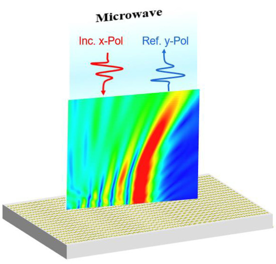
Figure 1.
Conceptual diagram of an Airy beam generator using metasurfaces design in reflective geometry.
We have shown that this unit cell can theoretically have an arbitrary controllable amplitude and binary phase response. After normalizing the amplitude, the amplitude and the phase are independent of the broadband frequency. Then, the amplitude is only associated with the angular rotation of the element. The incident linearly polarized (LP) wave is transformed at the metasurfaces’ aperture into a cross-polarized component of an amplitude-phase modulated profile yielding the desired Airy beam [31]. This unit cell facilitates the implementation of an Airy beam over a wide spectral range. The incoming LP waves are transformed into their cross-polarized components with amplitude-phase-modulated profiles on the metasurfaces’ aperture, resulting in the desired Airy beam.The diffraction-free, self-bending, and self-healing performance of the Airy beam are all simulated and demonstrated to verify the broadband characteristic of the proposed metasurfaces’ design by comparing these three properties at different frequencies. Furthermore, we also compare differences between the Airy beams generated by the metasurfaces with and without amplitude modulation, which further indicates the advantages of our design.
2. Materials and Methods
To improve the efficiency of metasurfaces, there has been a growing interest in reflective metasurfaces due to their high efficiency. The design of a unit cell with arbitrary controllable amplitude and free combinations of binary heterodyne responses is crucial for generating Airy beams [32]. To achieve phase and amplitude modulation, we propose the use of dumbbell-type structures with different rotation angles θ as our basic units, as illustrated in Figure 2a.
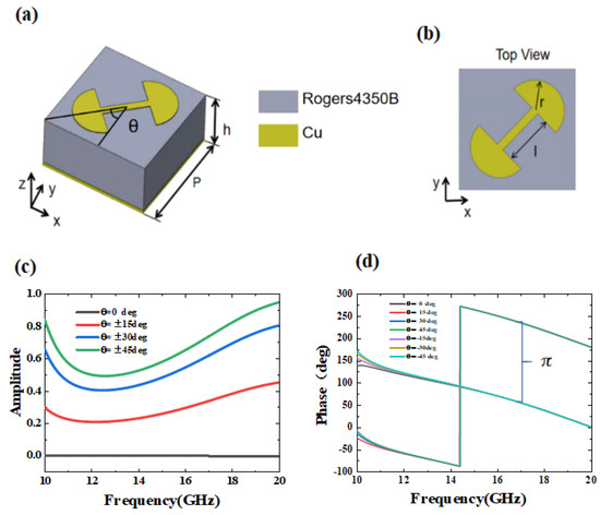
Figure 2.
Cross-polarization transmission coefficient response of the designed dumbbell-type structures: (a) a schematic of the dumbbell-type unit cell structure, (b) top views of the dumbbell-type unit cell, and (c,d) simulated cross-polarization transmission magnitude and phase performance of the dumbbell-type unit cell. The results are shown for different operating frequencies and as a function of the rotation angle.
We used CST Microwave Studio 2016 frequency domain solver to simulate and optimize the metasurfaces’ cell structure. Copper with a conductivity of σ = 5.8 × 10⁷ S/m was used as the metal, and Rogers 4350 B with a dielectric constant of 3.5 and a loss tangent of 0.0027 was used as the dielectric layer. The low-loss tangent of the dielectric substrate ensured high reflectivity over a wide frequency range, while the minimal metal loss in the microwave region further reduced energy absorption. Our design goal was to maximize the polarization conversion efficiency. After several simulations and continuous adjustment of the structural parameters, we determined the optimal structure parameters to be P = 6 mm, h = 1.524 mm, t = 35 μm, r = 1.5 mm, l = 2.5 mm, b = 0.4 mm.
The dumbbell-shaped unit cell demonstrates outstanding cross-polarization transmission performance, with a normalized transmission coefficient amplitude that can be adjusted between 0 and 1, while maintaining a binary phase of 0–π. This is illustrated in Figure 2c,d, indicating that the unit cell is well-suited for producing Airy beams. It can be seen that the maximum transmission coefficient can reach approximately 0.9. As shown in Figure 2c when q = ±45°, the transmission coefficient is close to zero when θ is 0°or 180°. Furthermore, the phase response exhibits an essentially unchanged binary phase difference when the dumbbell structure is rotated to positive and negative angles. The amplitude response can synthesize the initial desired Airy profile amplitude, and the phase response matches the desired binary phase, as illustrated in Figure 2c,d. The amplitude and phase response of the dumbbell-shaped cell can be well-controlled over a wide bandwidth, making it possible to generate broadband Airy beams.
When designing an array structure for generating an Airy beam, two critical factors must be taken into account. Firstly, the ideal Airy beam demands a suitable number of cell structures in a specific direction. Secondly, the bending of the beam is influenced by the number of unitary structures [29].
The amplitude and phase responses obtained from Figure 2c,d were utilized to create the dumbbell rotation angles at various positions of the incident plane wavefront when generating the initial Airy beam profile. Due to the compact size of the cell (6 mm) designed in this study, 40 cells can be placed on the one-dimensional Airy beam generating metasurfaces, as illustrated in Figure 3c.
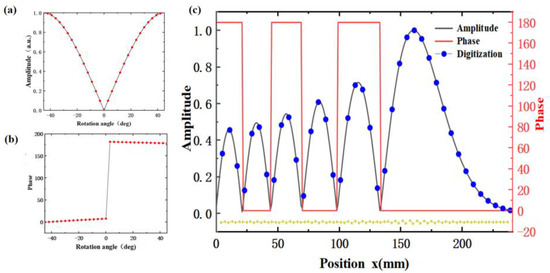
Figure 3.
(a) Simulated amplitude transmission, and (b) phase for dumbbell–type structures at different angles, (c) amplitude and phase profile of the Airy beam generators along the x–direction, Location distribution of dumbbells along the x–direction.
According to the principle outlined in [4], the Airy beam wave packet of finite energy can be described as:
In the equation, Ai represents the Airy function, where s = x/x0 is the dimensionless transverse coordinate, ξ = z/kx02 is the normalized propagation distance, w denotes the scale length, k is the free-space wave vector, a is the Airy truncation factor, and the attenuation parameter a must be a small positive number, significantly less than 1, to ensure that the desired Airy beam effect can be achieved. The amplitude and phase distributions along the variable surface profile (z = 0) can be obtained immediately from the diffraction-free properties of the Airy beam. According to the diffraction-free property of the Airy beam, the amplitude and phase distributions along the variable surface profile (z = 0) can be used as the initial field envelope of the one-dimensional Airy beam, as shown below:
and the amplitude and phase distribution must satisfy
According to the Equation (1), it can be inferred that the Airy function’s magnitude is a slowly decaying oscillating function, and the envelope of the Airy beam amplitude can be represented as a series of peak intensity distributions. The required phase should consist of two alternating sections with values of 0 and π.
The reflective cell structure proposed in the previous section satisfies this requirement, as illustrated in Figure 3a,b, enabling us to evolve the encoding of the Airy beam profile through sampling. To realize the metasurfaces’ Airy beam generator, we need to disperse the amplitude and phase distribution over the metasurfaces’ aperture, taking into account the lattice constant p = 6 mm. We designed separate samples using 1D Airy functions, with fixed parameters of a = 0.04 and x0 = 0.02 in Equation (1). As the metasurfaces feature 1D amplitude and phase distribution along the x-direction, they remain identical for the meta-atoms along the y-column. To achieve this, we designed an amplitude and phase distribution along the x-direction, as shown in Figure 3c.
To ease the determination of the rotation angle of the dumbbell, we normalize the transmission amplitude such that it has the same maximum value as the envelope of the Airy beam amplitude. By dividing the Airy function amplitude and phase distribution into 40 equal segments, a dumbbell-type structure with different rotation angles can describe the exponential decay characteristics. Each section of the Airy function’s transmission amplitude corresponds to a distinct rotation angle of the dumbbell-type structure, with the distribution of 40 dumbbells with different rotation angles shown in Figure 3c. As a result, we can achieve exponential decay characteristics using dumbbell-type structures with different rotation angles.
3. Results
3.1. Spectrum
To validate the design of the reflective Airy beam generator, we conducted simulations using the finite-difference time-domain (FDTD) method in CST Microwave Studio. The boundary conditions are constructed as periodic boundary conditions along the x- and y-directions to simulate repeated infinite cell planes; thus, mutual coupling between adjacent components can be considered. The z-direction was set as an open boundary to simulate electromagnetic wave propagation in a vacuum. Figure 4a,c illustrate the intensity distribution in the xoz plane at three different frequencies, 10 GHz, 15 GHz, and 20 GHz, respectively.
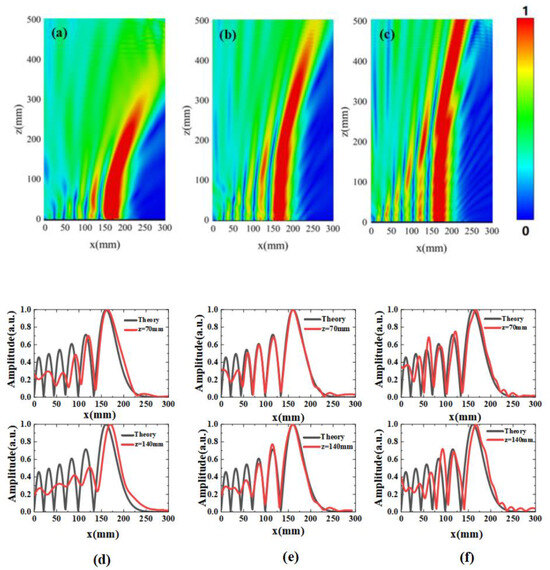
Figure 4.
The simulated electric field distributions of the produced Airy beams with amplitude modulation are shown at (a) 10 GHz, (b) 15 GHz, and (c) 20 GHz. Additionally, the simulated amplitude distribution of the metasurfaces in reflection geometry on the xoz plane is presented at (d) 10 GHz, (e) 15 GHz, and (f) 20 GHz.
Even after a long propagation distance, the parabolic trajectory and constant electric field intensity are distinguishable, demonstrating diffraction-free and self-bending characteristics at these frequencies. Furthermore, Figure 4 provides a quantitative comparison between the numerical and theoretical results for two selected slices in Figure 4a–c, corresponding to different propagation distances at three different frequencies. The results clearly indicate that the numerically generated 1D Airy beam matches the theoretical model in the frequency range of 10–20 GHz.
The 1D metasurfaces array we designed successfully generates broadband 1D Airy beams, and the numerical simulation results are consistent with the theoretical results. Figure 4d–f plot the normalized intensity distributions of the Airy beams generated at z = 70 mm and 140 mm at the three frequencies, which agree reasonably well with the ideal Airy distribution.
3.2. Properties
The half-height full width of the main flap is a crucial parameter for evaluating the diffraction-free nature of Airy beams. Figure 5a–c depict the half-height full widths of Airy beams at 10, 15, and 20 GHz. In this region, the half-width of the transmitted Airy beam remains relatively stable in comparison to the beginning to the region. Subsequently, the half-height width expands rapidly, and the diffraction-free property gradually disappears.
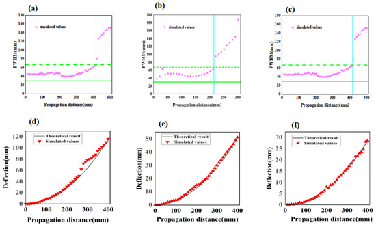
Figure 5.
The non-diffracting and self-bending properties of the Airy beam generated at 10 GHz, 15 GHz, and 20 GHz were validated, (a–c) for non-diffraction of Airy beams, which depicts the variation of width at half maximum of the main lobe along the z-direction (The non-diffraction zone is defined as the area between the green dashed and solid green lines, with a value of 1.5 times the mean FWHM value of the initial main beam. An oscillating pattern is observed in this zone, the area after the blue line represents the diffraction zone); (d–f) for the self-bending property of the Airy beam, (which demonstrates the deflection of the main beam versus propagation distance (z-direction) calculated from theory and simulation.).
The self-bending property of Airy beams is another unique characteristic. The deflection of the main flap can be described using the following equation:
Figure 5d–f show the deflection of the main flap of the Airy beam at three operating frequencies. The main flap of the Airy beam followed a smooth trajectory in the diffraction-free region, which agreed well with the theoretical calculation described in Equation (5).
Furthermore, the distinctive self-healing properties of the Airy beam were well-studied through the placement of a rectangular metal obstacle of size 10 mm × 6 mm in front of the centrally located main flap. Figure 6a–c demonstrate the distributions of the electric field with the metal obstacle at 15 GHz. The insets of Figure 6d–f show that the introduction of an obstacle can partially alter the beam profile due to diffraction. However, the perturbed beam profile can self-recover after passing through an obstacle. The normalized field intensity distributions of the Airy beam with obstacles generated at z = 80 mm and 180 mm are plotted in the figure panel. The field intensity of the main flap at z = 80 mm approached zero, passed through the metal obstacle, and gradually recovered to the field intensity distribution of the Airy function at z = 180 mm.
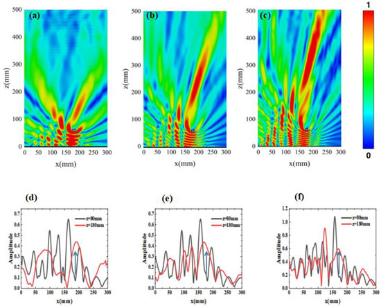
Figure 6.
The self-healing properties of Airy beams: the result of the main beam deflection of an Airy beam with an obstacle (rectangular metal obstacle of 10 mm × 6 mm placed on the main lobe propagation path); (a–c) self-healing properties of Airy beams verified through simulation in complex environments containing obstacles; the simulated amplitude distribution on the xoz plane at frequencies of (d) 10 GHz, (e) 15 GHz, and (f) 20 GHz.
To compare the effects of amplitude modulation, Figure 7 illustrates the electric field distribution of the generated Airy beam at different amplitude modulation levels. The inset of the figure compares the normalized intensity of the Airy beam generated at 70 mm from the metasurfaces (denoted by a white line) with the ideal Airy beam (denoted by a red line).
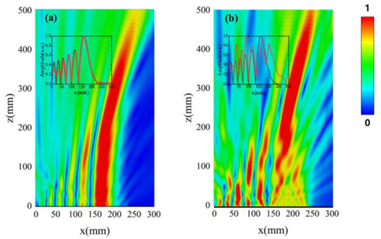
Figure 7.
The electric field distribution of the generated Airy beam was simulated, as shown in (a) with full amplitude modulation, and (b) without amplitude modulation. (The inset compares the normalized intensities between the generated Airy beam (denoted by a red line) and ideal Airy beam (denoted by a black line) at a distance of 80 mm from the metasurfaces).
Figure 7b displays the Airy beam obtained without amplitude modulation, where only the phase is modulated by two ±45° dumbbell structures. Despite the clear self-bending and diffraction-free features, the spatial spectrum of the near-field profile (in wave number space) closely resembles that of a rectangular wave. From the inset of Figure 7b, it is evident that the normalized near-field optical intensity distribution is significantly different from the ideal Airy beam intensity distribution, with the deflection trajectory deviating from the design trajectory. Figure 7a shows the generated Airy beam with full amplitude modulation, where the amplitude was modulated according to the Airy function. The light-intensity distribution and diffraction-free characteristics are more reasonable because there is no need to adjust the light-intensity distribution based on the self-healing property. The normalized intensity in Figure 7a exhibits an exponential decay that is more consistent with the ideal Airy beam than that in Figure 7b.
4. Discussion
Based on our simulation results demonstration, we can synthesize two-dimensional (1D) microwave Airy beams with different main-lobe sizes, sidelobe levels, and quasi-nondiffracting propagation distances by adjusting key parameters such as x0 and decay factor a for a given operating frequency. This approach enables the construction of metasurfaces based on the relationship between the magnitude/phase response of the dumbbell-type structure unit and the 1D Airy beam packet. This provides a flexible and versatile method for generating desirable Airy beams with various characteristics. Additionally, the ability to synthesize Airy beams with different characteristics using a single metasurfaces’ design offers significant potential for applications in various fields, including microwave signal processing, sensing, and imaging.
The efficiency of our proposed method for generating Airy beams using metasur-faces is comparable to, and in some cases, higher than other methods for generating Airy beams. Transmission approaches for generating Airy beams often suffer from low efficiency due to the significant energy loss caused by diffraction and absorption in the optical elements used. Digital holography and spatial light modulators offer better efficiency, but they require complex and expensive setups. In contrast, our proposed method using metasurfaces offers high efficiency due to the ability to control the phase and amplitude of the reflected waves with high precision. Additionally, the use of metasurfaces allows for more straightforward fabrication and integration into existing microwave devices, which can further increase the overall efficiency of the system.
In addition to efficiency, the use of metasurfaces for generating Airy beams offers several other advantages. One advantage is the ability to achieve high-quality wave-front control, which can result in improved beam quality and reduced distortion. Metasurfaces can achieve this level of control by manipulating the local phase and amplitude of the reflected waves with subwavelength precision. Another advantage of using metasurfaces for generating Airy beams is their compatibility with a wide range of frequencies and waveforms. Metasurfaces can be designed to work with various types of electromagnetic waves, including microwaves, terahertz waves, and optical waves. This flexibility makes them suitable for a diverse range of applications.
Furthermore, metasurfaces are relatively easy to fabricate using standard lithography techniques, allowing for cost-effective and scalable production. This is in contrast to other methods for generating Airy beams, which often require specialized equipment and complex fabrication processes.
Overall, the use of metasurfaces for generating Airy beams offers several advantages over other existing methods, including high efficiency, precise wavefront control, compatibility with various frequencies and waveforms, and ease of fabrication. These advantages make metasurfaces a promising platform for the development of advanced electromagnetic devices in various fields.
5. Conclusions
In our proposed method for generating Airy beams, we designed and fabricated metasurfaces that could reflect and manipulate microwave radiation to create the desired Airy beam profile. The metasurfaces were composed of an array of subwavelength-sized metallic patches that were patterned on a dielectric substrate. By varying the shape and position of these patches, we were able to control the phase and amplitude of the reflected waves, which allowed us to create the Airy beam profile.
To demonstrate the performance of our method, we compared the numerically simulated results with the theoretical predictions. The simulation results showed excellent agreement with the simulations, verifying the effectiveness of our approach for generating high-efficiency and wideband Airy beams in microwave sections with reflective geometry.
The presented metasurfaces solve the challenge of simultaneously controlling amplitude and phase modulation. We demonstrated simplified metasurfaces that can generate an Airy beam with both phase and amplitude modulation, and we discussed the advantages of Airy beams with both modulation types in detail.
In conclusion, our proposed method offers a novel approach for generating Airy beams that could have important applications in areas such as microwave signal processing, imaging, and sensing. Furthermore, our approach using metasurfaces could be extended to other types of wavefront manipulation, offering a promising platform for the development of advanced electromagnetic devices.
Author Contributions
Z.W.: conceptualization, methodology, software, writing—original draft. Y.Q.: methodology, formal analysis. T.L.: validation, writing—review and editing, supervision. All authors have read and agreed to the published version of the manuscript.
Funding
This research was funded by the National Natural Science Foundation of China grant numbers 52105595.
Institutional Review Board Statement
Not applicable.
Informed Consent Statement
Not applicable.
Data Availability Statement
Data is unavailable due to privacy.
Conflicts of Interest
The authors declare no conflict of interest.
References
- Durnin, J.; Miceli, J., Jr.; Eberly, J.H. Diffraction-Free Beams. Appl. Phys. Lett. 1987, 58, 1499. [Google Scholar] [CrossRef]
- Durnin, J. Exact Solutions for Nondiffracting Beams. I. The Scalar Theory. J. Opt. Soc. Am. A 1987, 4, 651–654. [Google Scholar] [CrossRef]
- López-Mariscal, C.; Helmerson, K. Shaped Nondiffracting Beams. Opt. Lett. 2010, 35, 1215–1217. [Google Scholar] [CrossRef] [PubMed]
- Siviloglou, G.A.; Christodoulides, D.N. Accelerating Finite Energy Airy Beams. Opt. Lett. 2007, 32, 979–981. [Google Scholar] [CrossRef]
- Siviloglou, G.; Broky, J.; Dogariu, A.; Christodoulides, D. Observation of Accelerating Airy Beams. Appl. Phys. Lett. 2007, 99, 213901. [Google Scholar] [CrossRef] [PubMed]
- Broky, J.; Siviloglou, G.A.; Dogariu, A.; Christodoulides, D.N. Self-Healing Properties of Optical Airy Beams. Opt. Express. 2008, 16, 12880–12891. [Google Scholar] [CrossRef] [PubMed]
- Minovich, A.; Klein, A.E.; Janunts, N.; Pertsch, T.; Neshev, D.N.; Kivshar, Y.S. Generation and near-Field Imaging of Airy Surface Plasmons. Appl. Phys. Lett. 2011, 107, 116802. [Google Scholar] [CrossRef]
- Zhao, Z.; Zang, W.; Tian, J. Optical Trapping and Manipulation of Mie Particles with Airy Beam. J. Opt. 2016, 18, 025607. [Google Scholar] [CrossRef]
- Singh, B.K.; Nagar, H.; Roichman, Y.; Arie, A. Particle Manipulation Beyond the Diffraction Limit Using Structured Super-Oscillating Light Beams. Light Sci. Appl. 2017, 6, e17050. [Google Scholar] [CrossRef]
- Vettenburg, T.; Dalgarno, H.I.; Nylk, J.; Coll-Lladó, C.; Ferrier, D.E.; Čižmár, T.; Gunn-Moore, F.J.; Dholakia, K. Light-Sheet Microscopy Using an Airy Beam. Nat. Methods 2014, 11, 541–544. [Google Scholar] [CrossRef]
- He, H.; Kong, C.; Tan, X.-J.; Chan, K.Y.; Ren, Y.-X.; Tsia, K.K.; Wong, K.K. Depth-Resolved Volumetric Two-Photon Microscopy Based on Dual Airy Beam Scanning. Opt. Lett. 2019, 44, 5238–5241. [Google Scholar] [CrossRef] [PubMed]
- Tan, X.-J.; Kong, C.; Ren, Y.-X.; Lai, C.S.; Tsia, K.K.; Wong, K.K. Volumetric Two-Photon Microscopy with a Non-Diffracting Airy Beam. Opt. Lett. 2019, 44, 391–394. [Google Scholar] [CrossRef] [PubMed]
- Abdollahpour, D.; Suntsov, S.; Papazoglou, D.G.; Tzortzakis, S. Spatiotemporal Airy Light Bullets in the Linear and Nonlinear Regimes. Appl. Phys. Lett. 2010, 105, 253901. [Google Scholar] [CrossRef]
- Chong, A.; Renninger, W.H.; Christodoulides, D.N.; Wise, F.W. Airy–Bessel Wave Packets as Versatile Linear Light Bullets. Nat. Photonics 2010, 4, 103–106. [Google Scholar] [CrossRef]
- Siviloglou, G.; Broky, J.; Dogariu, A.; Christodoulides, D. Ballistic Dynamics of Airy Beams. Opt. Lett. 2008, 33, 207–209. [Google Scholar] [CrossRef]
- Dai, H.; Sun, X.; Luo, D.; Liu, Y. Airy Beams Generated by a Binary Phase Element Made of Polymer-Dispersed Liquid Crystals. Opt. Express 2009, 17, 19365–19370. [Google Scholar] [CrossRef]
- Panagiotopoulos, P.; Papazoglou, D.; Couairon, A.; Tzortzakis, S. Sharply Autofocused Ring-Airy Beams Transforming into Non-Linear Intense Light Bullets. Nat. Commun. 2013, 4, 2622. [Google Scholar] [CrossRef]
- Yu, N.; Genevet, P.; Kats, M.A.; Aieta, F.; Tetienne, J.-P.; Capasso, F.; Gaburro, Z. Light Propagation with Phase Discontinuities, Generalized Laws of Reflection and Refraction. Science 2011, 334, 333–337. [Google Scholar] [CrossRef]
- Holloway, C.L.; Kuester, E.F.; Gordon, J.A.; O’Hara, J.; Booth, J.; Smith, D.R. An Overview of the Theory and Applications of Metasurfaces: The Two-Dimensional Equivalents of Metamaterials. IEEE Trans. Antennas Propag. 2012, 54, 10–35. [Google Scholar] [CrossRef]
- Zhao, Y.; Alù, A. Manipulating Light Polarization with Ultrathin Plasmonic Metasurfaces. Phys. Rev. B 2011, 84, 205428. [Google Scholar] [CrossRef]
- Ding, G.; Chen, K.; Luo, X.; Zhao, J.; Jiang, T.; Feng, Y. Dual-Helicity Decoupled Coding Metasurface for Independent Spin-to-Orbital Angular Momentum Conversion. Adv. Mater. Technol. 2019, 11, 044043. [Google Scholar] [CrossRef]
- Guo, W.-L.; Wang, G.-M.; Chen, K.; Li, H.-P.; Zhuang, Y.-Q.; Xu, H.-X.; Feng, Y. Broadband Polarization-Conversion Metasurface for a Cassegrain Antenna with High Polarization Purity. Phys. Rev. Appl. 2019, 12, 014009. [Google Scholar] [CrossRef]
- Aieta, F.; Kats, M.A.; Genevet, P.; Capasso, F. Multiwavelength Achromatic Metasurfaces by Dispersive Phase Compensation. Science 2015, 347, 1342–1345. [Google Scholar] [CrossRef] [PubMed]
- Chen, W.T.; Zhu, A.Y.; Sisler, J.; Huang, Y.-W.; Yousef, K.M.; Lee, E.; Qiu, C.-W.; Capasso, F. Broadband Achromatic Metasurface-Refractive Optics. Nano Lett. 2018, 18, 7801–7808. [Google Scholar] [CrossRef]
- Guo, W.-L.; Wang, G.-M.; Hou, H.-S.; Chen, K.; Feng, Y. Multi-Functional Coding Metasurface for Dual-Band Independent Electromagnetic Wave Control. Opt. Express 2019, 27, 19196–19211. [Google Scholar] [CrossRef]
- Chen, K.; Zhang, N.; Ding, G.; Zhao, J.; Jiang, T.; Feng, Y. Active Anisotropic Coding Metasurface with Independent Real-Time Reconfigurability for Dual Polarized Waves. Adv. Mater. Technol. 2020, 5, 1900930. [Google Scholar] [CrossRef]
- Wang, C.; Yang, Y.; Liu, Q.; Liang, D.; Zheng, B.; Chen, H.; Xu, Z.; Wang, H. Multi-Frequency Metasurface Carpet Cloaks. Opt. Express 2018, 26, 14123–14131. [Google Scholar] [CrossRef]
- Li, Z.; Yao, K.; Xia, F.; Shen, S.; Tian, J.; Liu, Y. Graphene Plasmonic Metasurfaces to Steer Infrared Light. Nature 2015, 5, 12423. [Google Scholar] [CrossRef]
- Li, Z.; Cheng, H.; Liu, Z.; Chen, S.; Tian, J. Plasmonic Airy Beam Generation by Both Phase and Amplitude Modulation with Metasurfaces. Adv. Opt. Mater. 2016, 4, 1230–1235. [Google Scholar] [CrossRef]
- Song, E.Y.; Lee, G.Y.; Park, H.; Lee, K.; Kim, J.; Hong, J.; Kim, H.; Lee, B. Compact Generation of Airy Beams with C-Aperture Metasurface. Adv. Opt. Mater. 2017, 5, 1601028. [Google Scholar] [CrossRef]
- Guo, W.L.; Chen, K.; Wang, G.M.; Luo, X.Y.; Cai, T.; Zhang, C.B.; Feng, Y.J.A.M.T. Airy Beam Generation, Approaching Ideal Efficiency and Ultra Wideband with Reflective and Transmissive Metasurfaces. Adv. Opt. Mater. 2020, 8, 2000860. [Google Scholar] [CrossRef]
- Fan, Q.; Zhu, W.; Liang, Y.; Huo, P.; Zhang, C.; Agrawal, A.; Huang, K.; Luo, X.; Lu, Y.; Qiu, C. Broadband Generation of Photonic Spin-Controlled Arbitrary Accelerating Light Beams in the Visible. Nano Lett. 2018, 19, 1158–1165. [Google Scholar] [CrossRef] [PubMed]
Disclaimer/Publisher’s Note: The statements, opinions and data contained in all publications are solely those of the individual author(s) and contributor(s) and not of MDPI and/or the editor(s). MDPI and/or the editor(s) disclaim responsibility for any injury to people or property resulting from any ideas, methods, instructions or products referred to in the content. |
© 2023 by the authors. Licensee MDPI, Basel, Switzerland. This article is an open access article distributed under the terms and conditions of the Creative Commons Attribution (CC BY) license (https://creativecommons.org/licenses/by/4.0/).