Lines of Quasi-BICs and Butterworth Line Shape in Stacked Resonant Gratings: Analytical Description


 and
and 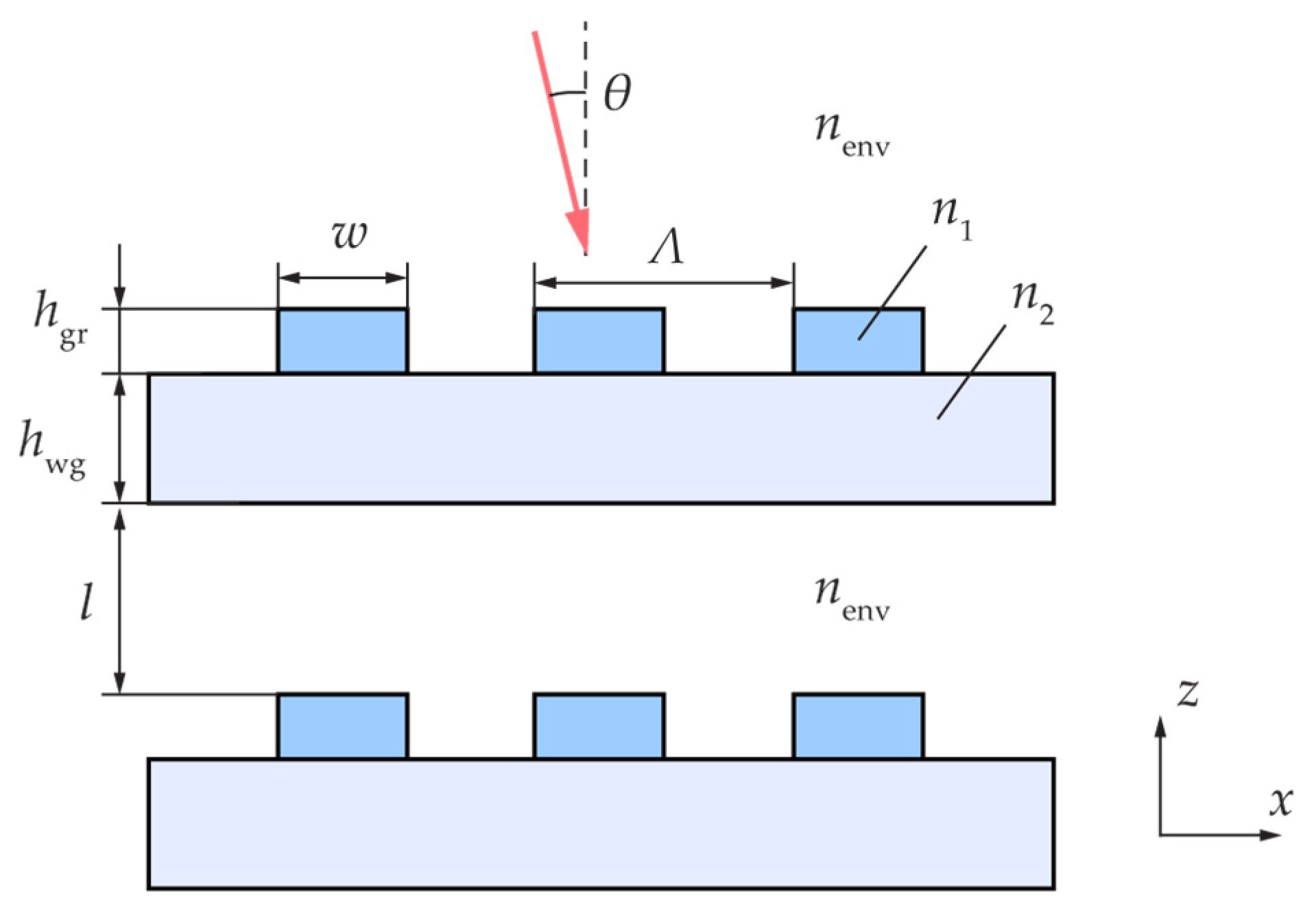
Abstract
1. Introduction
2. ω—kx Lorentzian Line Shape in a Single Resonant Grating
2.1. Scattering Matrix
2.2. Lorentzian Line Shape in a Symmetric Structure
2.3. Lorentzian Line Shape in a Structure without a Horizontal Symmetry Plane
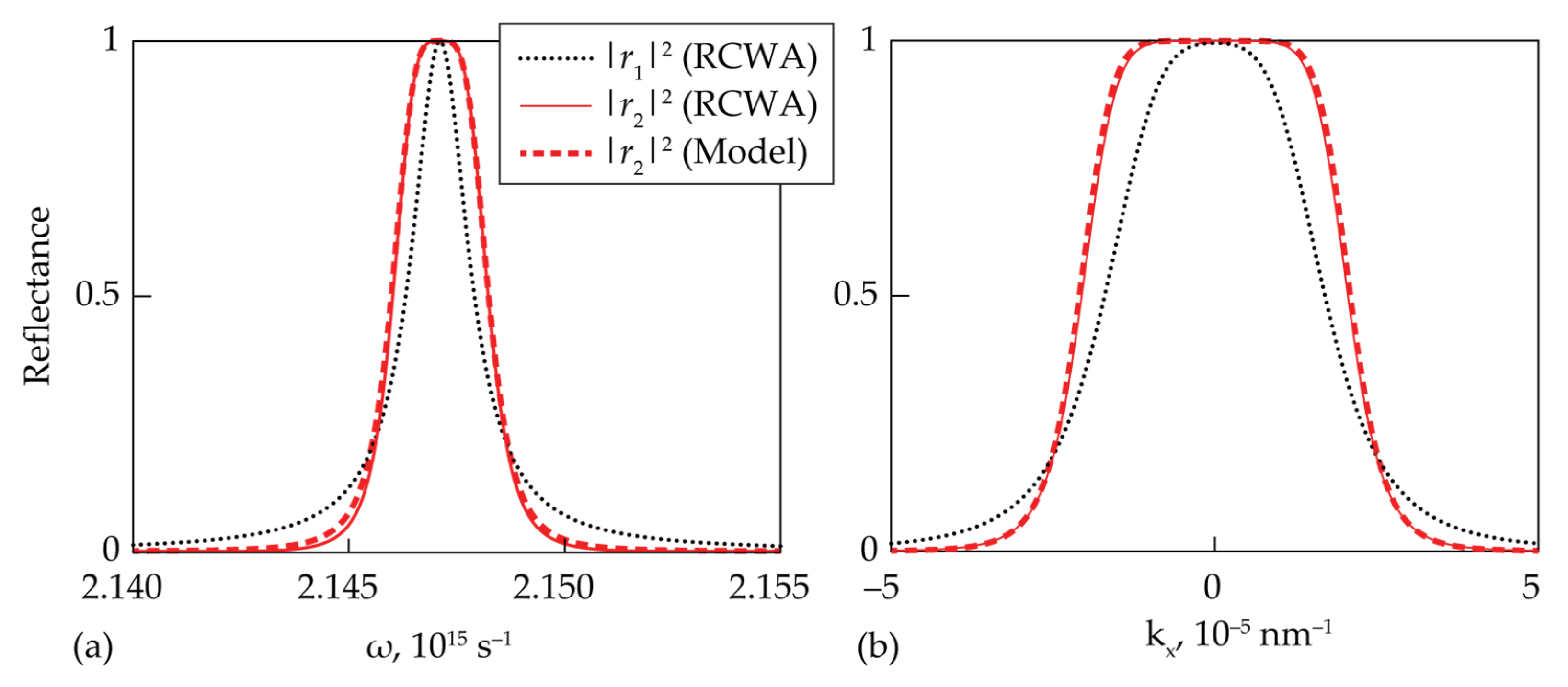
2.4. Numerical Example
3. ω—kx Resonant Approximation for Stacked Resonant Gratings
4. Butterworth Filters Based on Stacked Resonant Gratings
4.1. Second-Order Butterworth Filter for Temporal Signals
4.2. Fourth-Order Quasi-Butterworth Filter for Spatial Signals
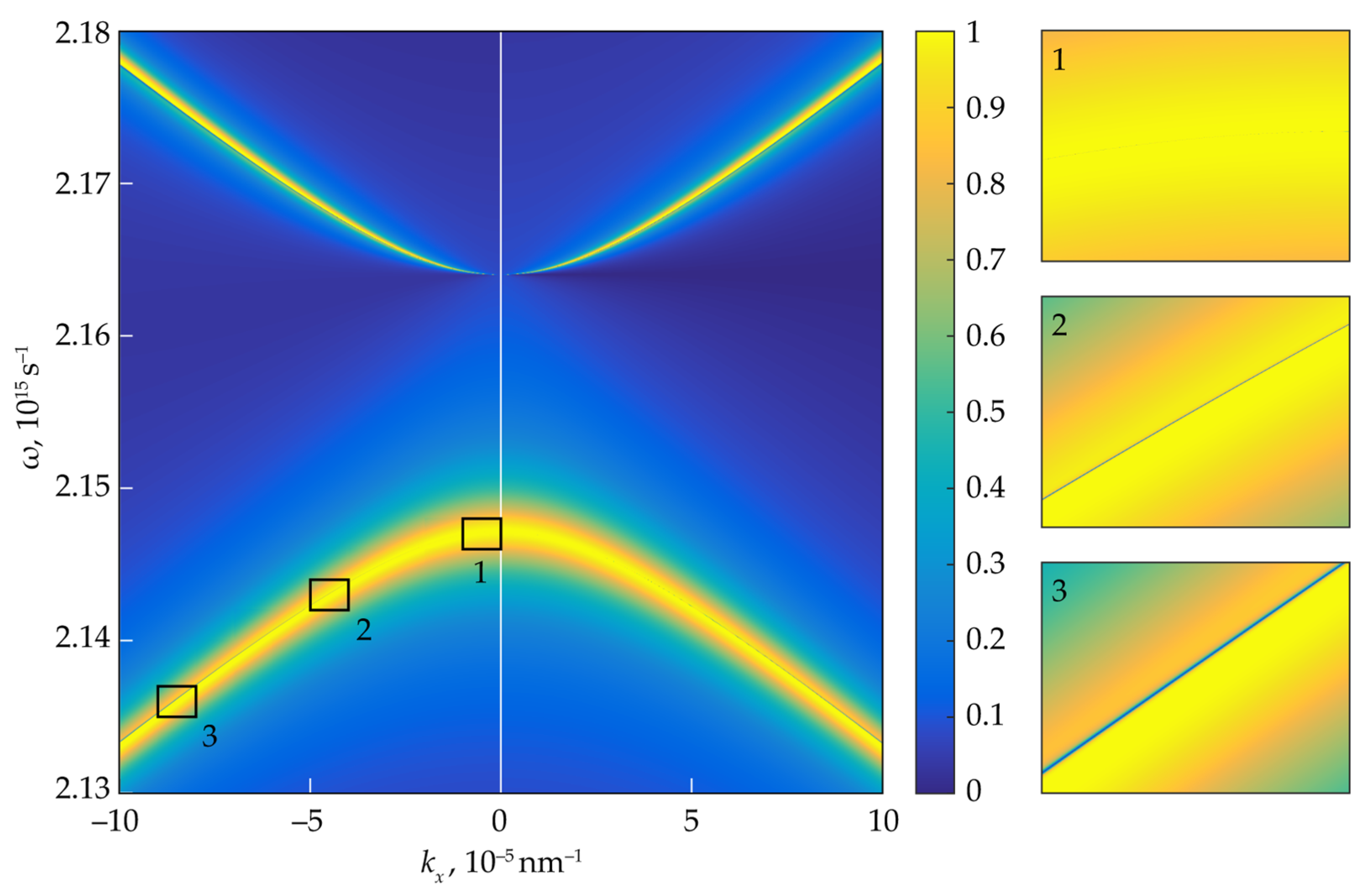
5. BICs and Lines of Quasi-BICs in Stacked Resonant Gratings
6. Conclusions
Author Contributions
Funding
Institutional Review Board Statement
Informed Consent Statement
Data Availability Statement
Conflicts of Interest
References
- Quaranta, G.; Basset, G.; Martin, O.J.; Gallinet, B. Recent advances in resonant waveguide gratings. Laser Photonics Rev. 2018, 12, 1800017. [Google Scholar] [CrossRef]
- Suh, W.; Fan, S. Mechanically switchable photonic crystal filter with either all-pass transmission or flat-top reflection characteristics. Opt. Lett. 2003, 28, 1763–1765. [Google Scholar] [CrossRef]
- Jacob, D.K.; Dunn, S.C.; Moharam, M.G. Flat-top narrow-band spectral response obtained from cascaded resonant grating reflection filters. Appl. Opt. 2002, 41, 1241–1245. [Google Scholar] [CrossRef] [PubMed]
- Ko, Y.H.; Magnusson, R. Flat-top bandpass filters enabled by cascaded resonant gratings. Opt. Lett. 2016, 41, 4704–4707. [Google Scholar] [CrossRef]
- Doskolovich, L.L.; Bezus, E.A.; Bykov, D.A.; Golovastikov, N.V.; Soifer, V.A. Resonant properties of composite structures consisting of several resonant diffraction gratings. Opt. Express 2019, 27, 25814–25828. [Google Scholar] [CrossRef] [PubMed]
- Song, H.Y.; Kim, S.; Magnusson, R. Tunable guided-mode resonances in coupled gratings. Opt. Express 2009, 17, 23544–23555. [Google Scholar] [CrossRef]
- Gippius, N.A.; Weiss, T.; Tikhodeev, S.G.; Giessen, H. Resonant mode coupling of optical resonances in stacked nanostructures. Opt. Express 2010, 18, 7569–7574. [Google Scholar] [CrossRef]
- Weiss, T.; Gippius, N.A.; Granet, G.; Tikhodeev, S.G.; Taubert, R.; Fu, L.; Schweizer, H.; Giessen, H. Strong resonant mode coupling of Fabry–Perot and grating resonances in stacked two-layer systems. Photonics Nanostructures Fundam. Appl. 2011, 9, 390–397. [Google Scholar] [CrossRef]
- Letartre, X.; Mazauric, S.; Cueff, S.; Benyattou, T.; Nguyen, H.S.; Viktorovitch, P. Analytical non-Hermitian description of photonic crystals with arbitrary lateral and transverse symmetry. Phys. Rev. A 2022, 106, 033510. [Google Scholar] [CrossRef]
- Gromyko, D.A.; Dyakov, S.A.; Tikhodeev, S.G.; Gippius, N.A. Resonant mode coupling approximation for calculation of optical spectra of stacked photonic crystal slabs Part I. Photonics Nanostructures Fundam. Appl. 2023, 53, 101109. [Google Scholar] [CrossRef]
- Gromyko, D.A.; Dyakov, S.A.; Tikhodeev, S.G.; Gippius, N.A. Resonant mode coupling approximation for calculation of optical spectra of stacked photonic crystal slabs Part II. Photonics Nanostructures Fundam. Appl. 2023, 53, 101110. [Google Scholar] [CrossRef]
- Butterworth, S. On the theory of filter amplifiers. Wirel. Eng. 1930, 7, 536–541. [Google Scholar]
- Hsu, C.W.; Zhen, B.; Stone, A.D.; Joannopoulos, J.D.; Soljačić, M. Bound states in the continuum. Nat. Rev. Mater. 2016, 1, 16048. [Google Scholar] [CrossRef]
- Marinica, D.C.; Borisov, A.G.; Shabanov, S.V. Bound states in the continuum in photonics. Phys. Rev. Lett. 2008, 100, 183902. [Google Scholar] [CrossRef] [PubMed]
- Bykov, D.A.; Doskolovich, L.L.; Golovastikov, N.V.; Soifer, V.A. Time-domain differentiation of optical pulses in reflection and in transmission using the same resonant grating. J. Opt. 2013, 15, 105703. [Google Scholar] [CrossRef]
- Bykov, D.A.; Doskolovich, L.L. ω−kx Fano line shape in photonic crystal slabs. Phys. Rev. A 2015, 92, 013845. [Google Scholar] [CrossRef]
- Bykov, D.A.; Bezus, E.A.; Doskolovich, L.L. Coupled-wave formalism for bound states in the continuum in guided-mode resonant gratings. Phys. Rev. A 2019, 99, 063805. [Google Scholar] [CrossRef]
- Sun, K.; Jiang, H.; Bykov, D.A.; Van, V.; Levy, U.; Cai, Y.; Han, Z. 1D quasi-bound states in the continuum with large operation bandwidth in the ω∼k space for nonlinear optical applications. Photonics Res. 2022, 10, 1575–1581. [Google Scholar] [CrossRef]
- Gippius, N.A.; Tikhodeev, S.G.; Ishihara, T. Optical properties of photonic crystal slabs with an asymmetrical unit cell. Phys. Rev. B 2005, 72, 045138. [Google Scholar] [CrossRef]
- Liu, X.; Chen, S.; Zang, W.; Tian, J. Triple-layer guided-mode resonance Brewster filter consisting of a homogenous layer and coupled gratings with equal refractive index. Opt. Express 2011, 19, 8233–8241. [Google Scholar] [CrossRef]
- Sang, T.; Wang, Y.; Li, J.; Zhou, J.; Jiang, W.; Wang, J.; Chen, G. Bandwidth tunable guided-mode resonance filter using contact coupled gratings at oblique incidence. Opt. Commun. 2017, 382, 138–143. [Google Scholar] [CrossRef]
- Moharam, M.G.; Grann, E.B.; Pommet, D.A.; Gaylord, T.K. Formulation for stable and efficient implementation of the rigorous coupled-wave analysis of binary gratings. J. Opt. Soc. Am. A 1995, 12, 1068–1076. [Google Scholar] [CrossRef]
- Li, L. Formulation and comparison of two recursive matrix algorithms for modeling layered diffraction gratings. J. Opt. Soc. Am. A 1996, 13, 1024–1035. [Google Scholar] [CrossRef]
- Bykov, D.A.; Doskolovich, L.L. Numerical methods for calculating poles of the scattering matrix with applications in grating theory. J. Light. Technol. 2012, 31, 793–801. [Google Scholar] [CrossRef]
- Bykov, D.A.; Bezus, E.A.; Morozov, A.A.; Podlipnov, V.V.; Doskolovich, L.L. Optical properties of guided-mode resonant gratings with linearly varying period. Phys. Rev. A 2022, 106, 053524. [Google Scholar] [CrossRef]
- Bykov, D.A.; Doskolovich, L.L.; Soifer, V.A. Temporal differentiation of optical signals using resonant gratings. Opt. Lett. 2011, 36, 3509–3511. [Google Scholar] [CrossRef]
- Golovastikov, N.V.; Bykov, D.A.; Doskolovich, L.L. Resonant diffraction gratings for spatial differentiation of optical beams. Quantum Electron. 2014, 44, 984–988. [Google Scholar] [CrossRef]
- Blanchard, C.; Hugonin, J.P.; Sauvan, C. Fano resonances in photonic crystal slabs near optical bound states in the continuum. Phys. Rev. B 2016, 94, 155303. [Google Scholar] [CrossRef]


Disclaimer/Publisher’s Note: The statements, opinions and data contained in all publications are solely those of the individual author(s) and contributor(s) and not of MDPI and/or the editor(s). MDPI and/or the editor(s) disclaim responsibility for any injury to people or property resulting from any ideas, methods, instructions or products referred to in the content. |
© 2023 by the authors. Licensee MDPI, Basel, Switzerland. This article is an open access article distributed under the terms and conditions of the Creative Commons Attribution (CC BY) license (https://creativecommons.org/licenses/by/4.0/).
Share and Cite
Golovastikov, N.V.; Bykov, D.A.; Bezus, E.A.; Doskolovich, L.L. Lines of Quasi-BICs and Butterworth Line Shape in Stacked Resonant Gratings: Analytical Description. Photonics 2023, 10, 363. https://doi.org/10.3390/photonics10040363
Golovastikov NV, Bykov DA, Bezus EA, Doskolovich LL. Lines of Quasi-BICs and Butterworth Line Shape in Stacked Resonant Gratings: Analytical Description. Photonics. 2023; 10(4):363. https://doi.org/10.3390/photonics10040363
Chicago/Turabian StyleGolovastikov, Nikita V., Dmitry A. Bykov, Evgeni A. Bezus, and Leonid L. Doskolovich. 2023. "Lines of Quasi-BICs and Butterworth Line Shape in Stacked Resonant Gratings: Analytical Description" Photonics 10, no. 4: 363. https://doi.org/10.3390/photonics10040363
APA StyleGolovastikov, N. V., Bykov, D. A., Bezus, E. A., & Doskolovich, L. L. (2023). Lines of Quasi-BICs and Butterworth Line Shape in Stacked Resonant Gratings: Analytical Description. Photonics, 10(4), 363. https://doi.org/10.3390/photonics10040363