2.1. Magnetic Error Analysis of Radial Magnetic Field
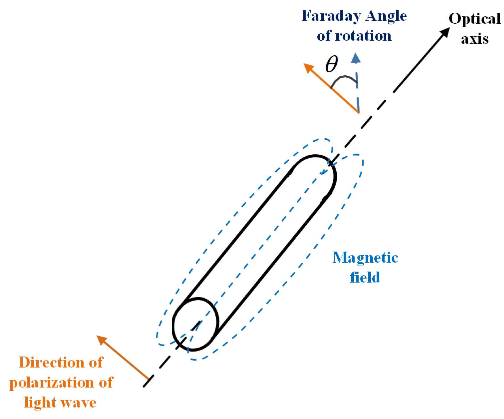
The linearly polarized light can be decomposed into a left-handed circularly polarized light and a right-handed circularly polarized light in the optical fiber. In consideration of the non-interference external environment, there will be no relative phase difference between two beams of circularly polarized light after propagating for a certain distance. Therefore, the polarization plane of the combined linearly polarized light remains unchanged. When the parallel magnetic field applied on the propagation direction of the light wave, the relative phase of the left and right circularly polarized light changes due to the non-diagonal component of the dielectric constant tensor, and the polarization plane of the light is rotated after the linearly polarized light emerges again. As is shown in
Figure 1, the optical rotation angle caused by the magneto-optical Faraday effect can be expressed as:
where
denotes the Faraday rotation angle,
V denotes the Verdet constant,
represents the parallel magnetic induction, and
L represents the transmission distance.
The Verdet constant of the polarization maintaining fiber (PMF) used in the fiber optic gyroscope is 6.4 × 10
−4 rad/(m·mT). The magneto-optical Faraday rotation angle is proportional to the magnetic field strength and propagation distance. In addition, the magneto-optical Faraday rotation angle is related to the propagation position of light.
Figure 2 shows the decomposition of the radial magnetic field at any position in the XOY plane.
is the angle between the radial magnetic field and the
X-axis of the coordinate axis, and the parallel component
in the vibration plane is extracted at the z point (its vertical component will not affect the beam). The magnetic induction of the radial magnetic field is:
. When the direction of the magnetic field is fixed with the included angle of the fiber coil, the magneto-Faraday rotation angle is related to the position of the fiber in the coil.
In order to establish the radial magnetic-induced error model, it is a common method to analyze the phase change generated by clockwise (CW) and counterclockwise (CCW) beams through the Jones matrix. The infinitesimal element method is employed to analyze the birefringence of the fiber coil. The fiber coil can be decomposed into a micro-element with length
z, and the magneto-Faraday rotation angle of fiber coil units with length
z can be considered as uniformly generated. Therefore, the electric field component of the polarized light incident into the fiber coil can be expressed as:
where
Ex(
z) and
Ey(
z) are the electric field components in the
X-axis and
Y-axis directions at z point, respectively.
Ex(0) and
Ey(0) are the electric field components in the
X-axis and
Y-axis directions when the fiber enters the cavity, respectively. Δ
β represents the inherent linear birefringence of the fiber,
twi represents the circular birefringence caused by twisting, and
ξi denotes the circular birefringence caused by the magneto-optical Faraday effect.
Then, in the i-th micro-element fiber, the circular birefringence caused by the magneto-optical Faraday effect can be expressed as:
It can be seen from the above formula that in addition to the circular birefringence generated by the Faraday rotation effect for the CW and CCW directions, there is also a torsional circular birefringence due to the torsional circular birefringence introduced by the fiber during the drawing process. Typically, the fiber torsion introduced by fiber drawing process is sinusoidally periodic. Assuming that the fiber is CW twisted, the circular birefringence caused by the magneto-optical Faraday effect and the fiber torsion towards the same direction are superposed when the light wave propagates CW, and, on the contrary, cancel each other out when the light wave propagates CCW. The Jones matrix for CCW propagation can be expressed as:
The light wave in the CW direction is injected from the port on one side of the fiber coil through
n micro-units and then exits from the port on the other side, while the light wave in the CCW direction propagates in the fiber coil along the opposite direction. Then, the electric field component
E+ of the light wave in the CW direction and the electric field component
E- in the CCW direction can be expressed as [
6]:
Put Formulas (4) and (7) into the above formula, according to the Sagnac effect, the phase difference
generated by CW and CCW light waves can be expressed as:
Then, the magnetic error of the radial magnetic field generated by the Faraday magneto-optical effect is:
where
λ denotes the wavelength of light wave, c denotes the speed of light in vacuum,
Br represents the radial magnetic induction,
R represents the coil radius.
2.2. Magnetic Error Analysis of Axial Magnetic Field
In addition to the radial magnetic field, the fiber optic gyroscope will also be affected by the axial magnetic field. It can be seen from the previous analysis that the mode field distribution is asymmetric on the cross-section of the bending fiber. Therefore, the off-diagonal component of the dielectric constant tensor of the fiber is not zero. When the transverse magnetic field is applied, the transverse magnetic modes propagating CW and CCW cause a magneto-optical non-reciprocal phase shift, which will lead to magnetic-induced errors.
When an axial magnetic field is applied to a single-mode fiber, the propagation constants of CW
and CW light waves
can be expressed as:
where
ω represents the spatial angular frequency,
ε0 represents the vacuum permittivity,
K denotes the relative permittivity,
μ0 denotes the relative permeability of the fiber, and
and
are the light wave unit vectors in the CW and CCW directions, respectively.
The integral area in the above formula is the entire cross-section of the fiber, and its denominator is the Poynting power in this mode. After normalizing the denominator and decomposing the relative permittivity
K into a diagonal matrix
K0 and an off-diagonal matrix Δ
K, we get:
The longitudinal electric field components of the CW light wave and the CCW light wave are equal in magnitude and opposite in sign, and the transverse electric field components are equal in magnitude and sign. The propagation constants of CW and CCW light waves can be obtained:
Then, the difference Δ
ρ between the propagation constants of CW and CCW light waves is described as:
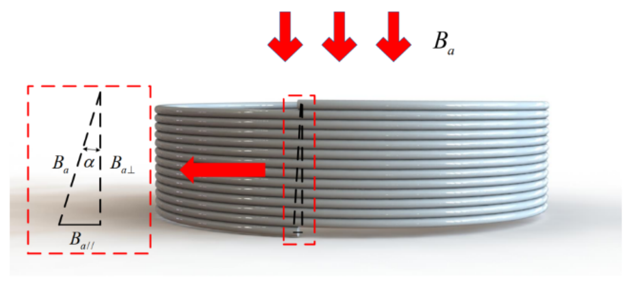
which shows the electric field component of the light wave is not symmetrical about the center point on the fiber cross-section when dielectric constant of a single-mode fiber has an off-diagonal component in axial magnetic field, resulting in a phase shift of the CW and CCW light waves. The magnitude of this phase shift is related to the strength of the magnetic field and the central asymmetry. Since the fiber coil is spirally rising close to the fiber skeleton during the winding process, as shown in
Figure 3. Each turn of fiber has a slight tilt angle relative to the central axis of the fiber coil. Therefore, when the axial magnetic field acts on the fiber coil, there is a parallel component and a vertical component of the axial magnetic field, which can be expressed as:
The helix angle
α of the fiber coil is expressed as:
where
h,
N, and
R represent coil height, number of turns, and radius, respectively.
For a fiber coil with a height of 13 mm, 72 turns in a single layer, and a winding radius of 30 mm, the helix angle is 0.052°. It can be determined by Equation (17) that the vertical component of the axial magnetic field is 1102 times that of the parallel component. Since the magnitude of the magnetic field referred to in this paper is that of the Earth’s magnetic field, the effect of the parallel component can be ignored. The homogeneous scalar wave equation obtained from the induced vector
in the single-mode fiber and Maxwell’s equation on the magnitude of the Earth’s magnetic field is:
where
ε represents the dielectric constant of the fiber, and
k represents the wave number in the fiber.
In general, the dielectric constant of the fiber is
ε =
n2, in which
n is the index of refraction. In order to facilitate the calculation, let the
Z-axis direction of the fiber be the light wave propagation direction, and the
X-axis direction be the fiber bending direction, then the relationship between the longitudinal component
and the transverse component
of the electric field inside the bent fiber is:
The transverse component of the electric field exhibits as Gaussian distribution, and the transverse electric field component
in the bent fiber is expressed as:
where
w represents the mode spot size.
When the axial magnetic field
Ba is applied on the fiber, paralleled to the y-direction, the induced vector
can be expressed as:
The resulting homogeneous scalar wave equation is:
Substituting Equation (22) Into Equation (19), the wave equation corresponding to the transverse electric field component can be obtained as:
Taking Equation (20) into the above equation and simplifying it, we calculated it as:
The right side of the equation is the perturbation component of
induced by the axial magnetic field. Use Gaussian approximation for the transverse electric field in Equation (24), the mode field distribution is expressed as:
Putting Equation (21) into the above equation, we obtained:
The propagation constant of the CW and CCW light waves change along the bent fiber. By normalizing
in the fiber section, the mode field offset
of the bent fiber under the action of the axial magnetic field is expressed as [
12]:
Since the mode field offset of the CW and CCW light waves in the fiber are equal in magnitude and opposite in direction, for the entire fiber coil, the phase difference caused by the axial magnetic field can be expressed as:
From the above formula, the expression of the axial magnetic-induced error of the fiber optic gyroscope can be deduced as:
2.3. Establishment of a Small IFOG Three-Dimensional Magnetically Induced Error Model
The bending fiber is subjected to both axial tension and radial compressive stress, which can be regarded as a curved cylindrical quartz rod. The stress distribution in the fiber is given by [
13]:
where
Y represent the Young’s modulus of the fiber,
ν represent Poisson’s ratio of the fiber.
The cladding diameter is fixed when the PMF is drawn from the preform, and the bending radius is related to both the initial radius of the fiber coil and the winding method. The bending radius of the fiber coil is required to be designed between 10 mm and 20 mm in the aerospace field. For such a bending radius, the difference in the bending radius between different layers cannot be ignored. Our previous work showed that for a fiber coil using the orthocyclic quadrupolar winding, the relationship between fiber length and fiber bending radius, as well as the refractive index and birefringence distribution models, can be expressed as [
9]:
where
Rin represents the innermost radius of the fiber coil,
Ri represents the radius of the first layer of the fiber coil,
Li represents the total length of the fiber wrapped around the fiber coil at the first layer,
N represents the number of turns of the fiber coil, and
M is the number of layers of the fiber coil,
p11 and
p12 represent the elastic optical coefficient of the fiber.
Take YOFC-PM-1310 80-18/135 panda PMF as an example. The specific parameters of the fiber are listed in
Table 1.
Figure 4 shows the relationship between birefringence and fiber length with a different winding radius where the birefringence increases first and then decreases with fiber length increasing. Additionally, it is illustrated that the bending radius of the fiber increases in a stepwise manner with length increasing, which is due to the fiber coil increases in length at different turns within the same layer while the bend radius remains the same. Moreover, since the fiber winding is from the midpoint to both ends, the smallest radius is found at the midpoint of the fiber coil, where the birefringence varies the most significantly. With the bending radius gradually increasing, the variation of birefringence is gradually decreasing. The smaller the initial bending radius, the greater the birefringence change.
As shown in
Figure 5, the magnetic field applied to the fiber optic gyro can be decomposed into two directions and calculated separately and then accumulated. Decompose the magnetic field
B with an angle
η to the vertical axis into an axial magnetic field and a radial magnetic field, and the magnetic error caused by the magnetic field at any angle can be expressed as:
Since the optical fiber is a non-magnetic conductive material, the intensity of the magnetic field will not change after passing through the multi-layer fiber, so the variation of the birefringence and refractive index caused by the bending radius varying only affect the magnitude of the magnetic error. The number of turns can be simplified when thebending radius of the fibers in the same layer is the same, only carrying out the accumulation calculation based on the layer. The expression of the three-dimensional magnetic induction error of the small IFOG can be given as follows:
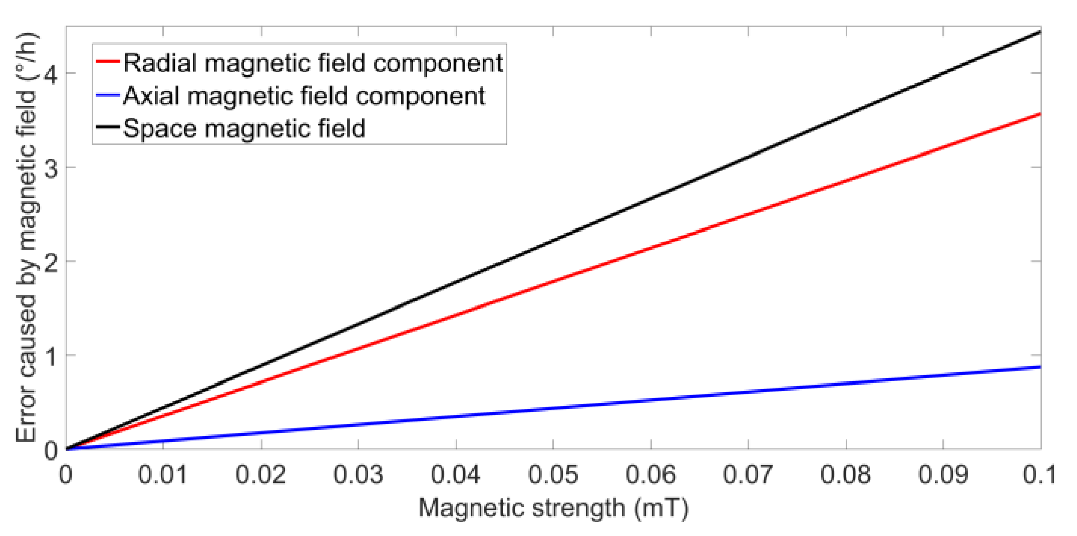
Next, the simulation analysis of the small IFOG fiber coil is carried out. The fiber is YOFC-PM-1310 80-18/135 panda-type PMF. The total length of the fiber coil is 300 m, the inner diameter is 0.026 m, the number of layers is 42, and the number of turns is 72. During the winding process, the torsional period of the fiber amplitude
tw(z) is about 0.2. To make the radial and axial magnetic field equal in intensity, the angle between the magnetic field and the fiber coil is set to 45°. The simulation results of the three-dimensional magnetic induced error under the magnetic field with the magnetic induction intensity of 0–0.1 mT are depicted in
Figure 6.
In
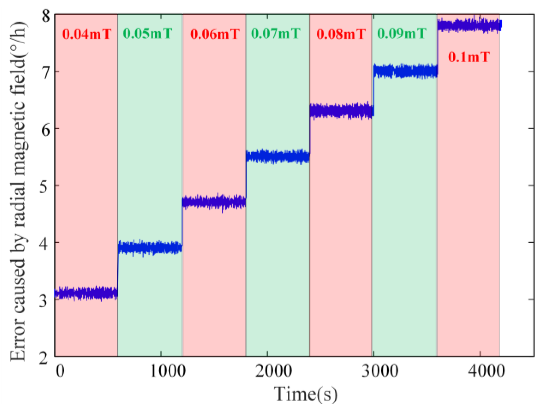
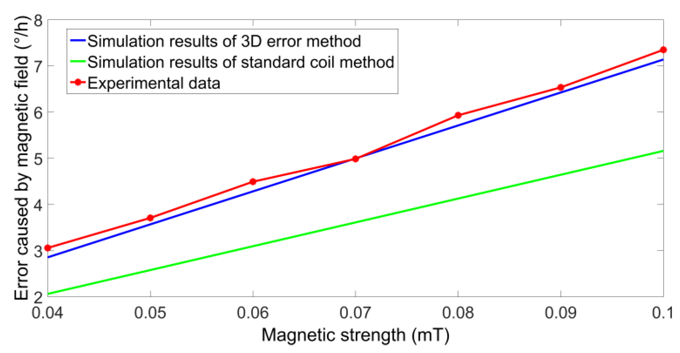
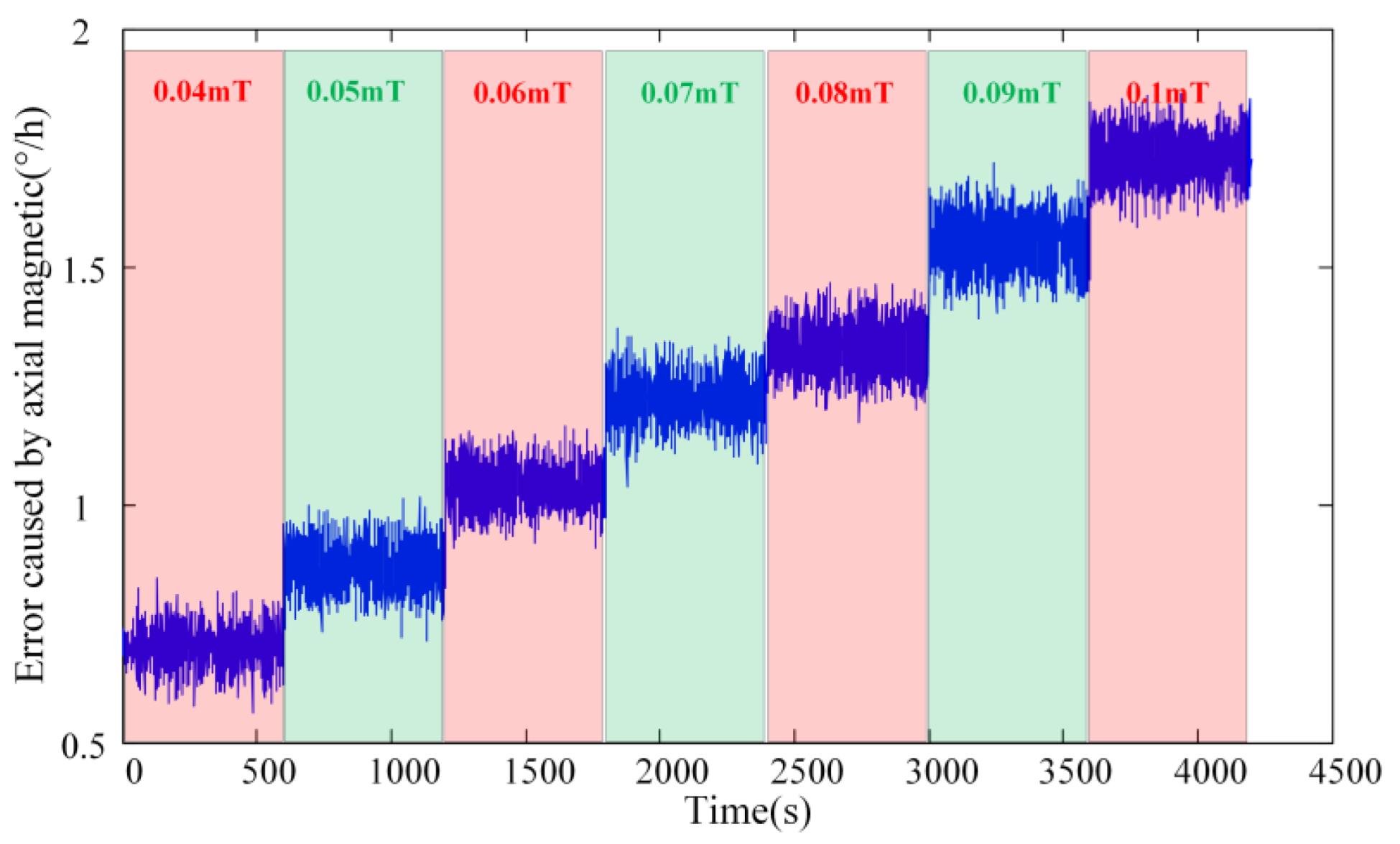
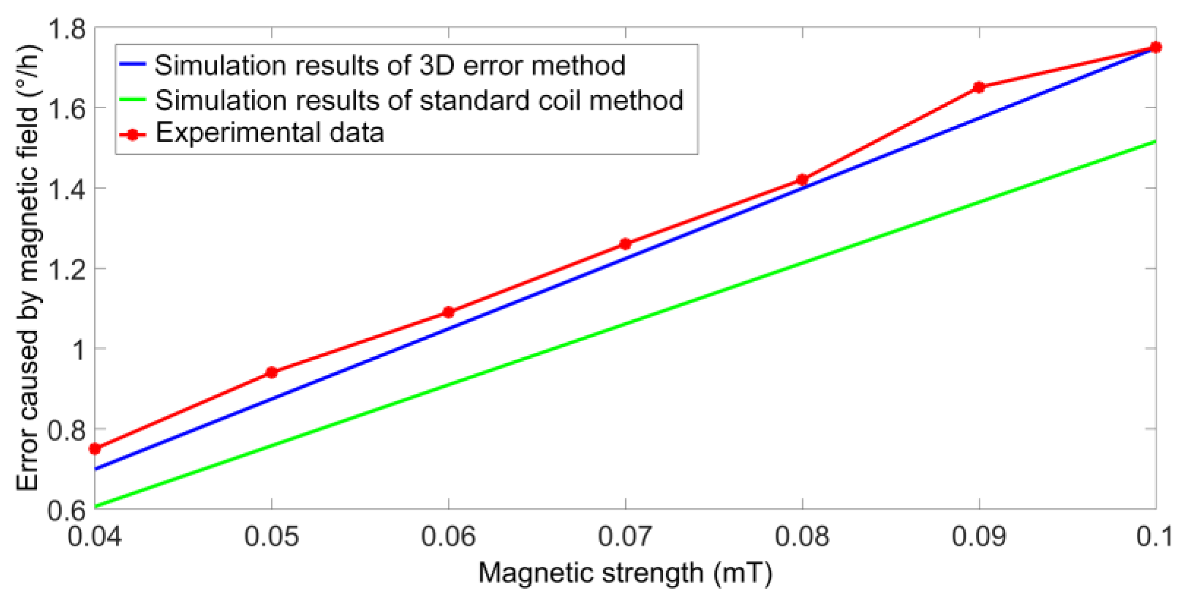
Figure 6, the black line is the magnitude of the magnetic error caused by the magnetic field, the red line is the magnitude of the magnetic error induced by the radial magnetic field, and the blue line is the magnitude of the magnetic error induced by the axial magnetic field. Since the intensity of the magnetic field in the radial and axial directions are equal, the radial magnetic field has a greater impact on the gyro.
