Communication

Sub-40 GHz Broadband Polarization Chaos Generation Using Mutually Coupled Free-Running VCSELs

1
Guangdong Provincial Key Laboratory of Photonics Information Technology, School of Information Engineering, Guangdong University of Technology, Guangzhou 510006, China
2
Key Laboratory of Advanced Transducers and Intelligent Control System, Ministry of Education, Taiyuan University of Technology, Taiyuan 030024, China
3
Science and Technology on Communication Laboratory, Institute of Southwestern Communication, Chengdu 610041, China
4
School of Computer Science and Electronic Engineering, Bangor University, Wales LL57 1UT, UK
*
Author to whom correspondence should be addressed.
Photonics 2023, 10(2), 219; https://doi.org/10.3390/photonics10020219
Submission received: 7 February 2023 / Revised: 15 February 2023 / Accepted: 16 February 2023 / Published: 17 February 2023
(This article belongs to the Special Issue Advancements in Semiconductor Lasers)

Abstract

:
We propose a simple method to generate broadband polarization chaos using two mutually coupled free-running vertical-cavity surface-emitting lasers (VCSELs). Specifically, we quantitatively investigate the effect of critical external parameters (bias current, frequency detuning and coupling coefficient) on the polarization chaos bandwidth in the scenarios of parallel injection and orthogonal injection, and reveal the physical mechanism of bandwidth enhancement in two scenarios. Final simulation results show that the bandwidth of chaotic signals obtained from parallel and orthogonal injection can reach 35.15 GHz and 32.96 GHz, respectively.

1. Introduction

Laser chaos has important applications in many fields such as random number generation [1,2,3,4,5], chaotic optical communications [6,7,8,9,10] and ranging lidars [11,12,13]. Semiconductor lasers are often used as chaotic light sources due to their complex dynamic characteristics and fast response [14]. However, limited by the relaxation oscillation, the chaotic signal generated by semiconductor lasers usually has the disadvantage of narrow bandwidth [15,16].
To overcome the issue, many schemes have been proposed to enhance chaos bandwidth. For example, Uchida et al. injected the chaotic signal into a slave laser to generate a broadband chaotic signal with 22 GHz bandwidth [17]. Lin et al. theoretically demonstrated that an optically injected subject to optoelectronic feedback could be used to achieve wideband chaos with a bandwidth above 22 GHz [18]. Schires et al. generated broadband chaos over 16 GHz bandwidth using a laser subjected to two external optical cavities [19]. Bouchez et al. obtained a wideband chaotic signal with 18 GHz bandwidth from a laser diode with phase-conjugate feedback [20]. Zhao et al. reported that delay-interfered self-phase modulated feedback could increase the chaos bandwidth to 30 GHz [21]. Hong et al. proved that the chaos with 11 GHz bandwidth could be generated via mutual coupling between a VCSEL operating in continuous-wave mode and a chaotic VCSEL [22]. Chai et al. implemented a chaotic signal with 13 GHz bandwidth based on two mutually coupled semiconductor lasers subjected to random feedback [23].
Among them, the mutually coupled structure of semiconductor lasers represents a class of typical scheme for broadband chaos generation. Every semiconductor laser used in most of mutually coupled systems commonly requires an external perturbation such as optical feedback to be firstly driven into chaotic oscillation, and their chaotic outputs are then injected into each other to realize the chaos bandwidth enhancement [24]. In consequence, a weak periodicity corresponding to the external cavity trip time is imposed in the chaotic outputs [25] and thus inevitably degrades the security [26]. Moreover, the introduction of external feedback cavity increases the complexity of these broadband chaos systems, which is not feasible for practical applications.
Polarization chaos, a new type of optical chaos, has been confirmed in recent years that it can be directly generated in a free-running VCSEL without additional external perturbation [27]. The physical mechanism behind this polarization chaos is nonlinear coupling between two elliptically polarized modes [28]. This simple structure not only satisfies the existing requirements for photonic integration, but also enables the elimination of periodicity in chaotic sources [29].
Considering the advantages of polarization chaos, we herein propose a method to generate bandwidth-enhanced chaos by mutually coupled two free-running chaotic 980 nm VCSELs in two cases of parallel and orthogonal injection. Through increasing the bias current, we first guarantee the free-running VCSEL works at a chaotic state. Based on this, we then investigate the effect of frequency detuning and coupling coefficient on the polarization chaos bandwidth in the mutually coupled configuration in detail. Final simulation results show that broadband chaos can be obtained in each of the polarization modes of VCSEL with an appropriate frequency detuning and coupling coefficient. For the case of parallel injection, the polarization chaos bandwidth can reach a maximum of 35.15 GHz. On the other hand, the chaos bandwidth achieves a value of 32.96 GHz in orthogonal injection. Such high bandwidths achieved by two simple free-running VCSELs are attributed to the physics of the laser chaotic polarization dynamics.

2. System Model and Theory

Figure 1 shows the schematic diagram of mutually coupled free-running VCSELs. Both the VCSELs operate in the chaotic state with no additional external perturbation. The specific investigations on broadband polarization chaos generation are divided into two scenarios: parallel injection and orthogonal injection. As shown in Figure 1a, the laser output from VCSEL1 is connected to a polarization beam splitter (PBS1) in order to select between vertical X polarization (XP) and parallel Y polarization (YP) modes. The lights of the XP and YP modes that have been attenuated by their respective neutral density filters (NDF1 and NDF2) are then injected into VCSEL2 via a second polarization beam splitter. The output of VCSEL2 undergoes a similar procedure, resulting in a mutually coupled structure. In this system, two distinct optical pathways of equal length are designed. This ensures that the coupling time delays for both polarization modes are the same and that the injected light from VCSEL1 and VCSEL2 has parallel linear polarization directions. As shown in Figure 1b, in the case of orthogonal injection, the lights of the XP and YP modes from VCSEL1 are injected orthogonally to the YP and XP modes of VCSEL2, respectively. Note that the light intensity inside the cavity is controlled by the bias current μ.
In our simulation, the polarization chaos dynamics of free-running VCSELs are described using the well-known spin-flip model (SFM) [30]. Considering the effect of mutually coupled fields, the SFM representing the slow-varying electric field complex amplitude (E), the total number of inversion carriers (N), and the spin-flipping difference in carrier number (n) can be extended as follows:
d E x 1 , 2 d t = κ 1 , 2 1 + i α 1 , 2 N 1 , 2 1 E x 1 , 2 + i n 1 , 2 E y 1 , 2 γ α 1 , 2 + i γ p 1 , 2 E x 1 , 2 + k i n j x 2 , 1 E x 2 , 1 t τ c e i ω 0 2 , 1 τ c i Δ ω E x 1 , 2 + F x 1 , 2
d E y 1 , 2 d t = κ 1 , 2 1 + i α 1 , 2 N 1 , 2 1 E y 1 , 2 i n 1 , 2 E x 1 , 2 + γ α 1 , 2 + i γ p 1 , 2 E y 1 , 2 + k i n j y 2 , 1 E y 2 , 1 t τ c e i ω 0 2 , 1 τ c i Δ ω E y 1 , 2 + F y 1 , 2
d N 1 , 2 d t = γ N 1 , 2 N 1 , 2 1 + E x 1 , 2 2 + E y 1 , 2 2 μ 1 , 2 γ N 1 , 2 i n 1 , 2 E y 1 , 2 E x 1 , 2 E x 1 , 2 E y 1 , 2
d n 1 , 2 d t = γ s 1 , 2 n 1 , 2 γ N 1 , 2 n 1 , 2 E x 1 , 2 2 + E y 1 , 2 2 γ N 1 , 2 i N 1 , 2 E y 1 , 2 E x 1 , 2 E x 1 , 2 E y 1 , 2
In these equations, Equations (1) and (2) represent the expressions of the variation in the XP and YP fields during parallel injection. In orthogonal injection, kinj x and Ex in the second row of Equation (1) should be substituted with kinj y and Ey, while kinj y and Ey in the second row of Equation (2) should be substituted with kinj x and Ex. The subscripts x and y stand for the XP and YP modes of the VCSELs, while the superscripts 1 and 2 represent VCSEL1 and VCSEL2, respectively. ω0 = (ω1 + ω2)/2 is the average angular frequency of the system, where ω1 and ω2 are the angular frequency of VCSEL1 and VCSEL2, respectively. Δω = (ω2ω1)/2 is the angular frequency detuning, and Fx,y represent the terms for noise resulting from spontaneous emission. Note that in our numerical simulation, Δf = Δω/2π denotes the optical frequency detuning between VCSEL1 and VCSEL2, which varies from −40 GHz to 40 GHz. Beyond this range, the spectra of the two lasers begin to separate, which is detrimental to bandwidth enhancement. kinj = rinj/τin is the coupling coefficient, where rinj is the injection strength and τin is the round-trip time to the internal cavity of VCSEL. The other parameters and values in the simulation are shown in Table 1.

3. Simulation Results and Analysis

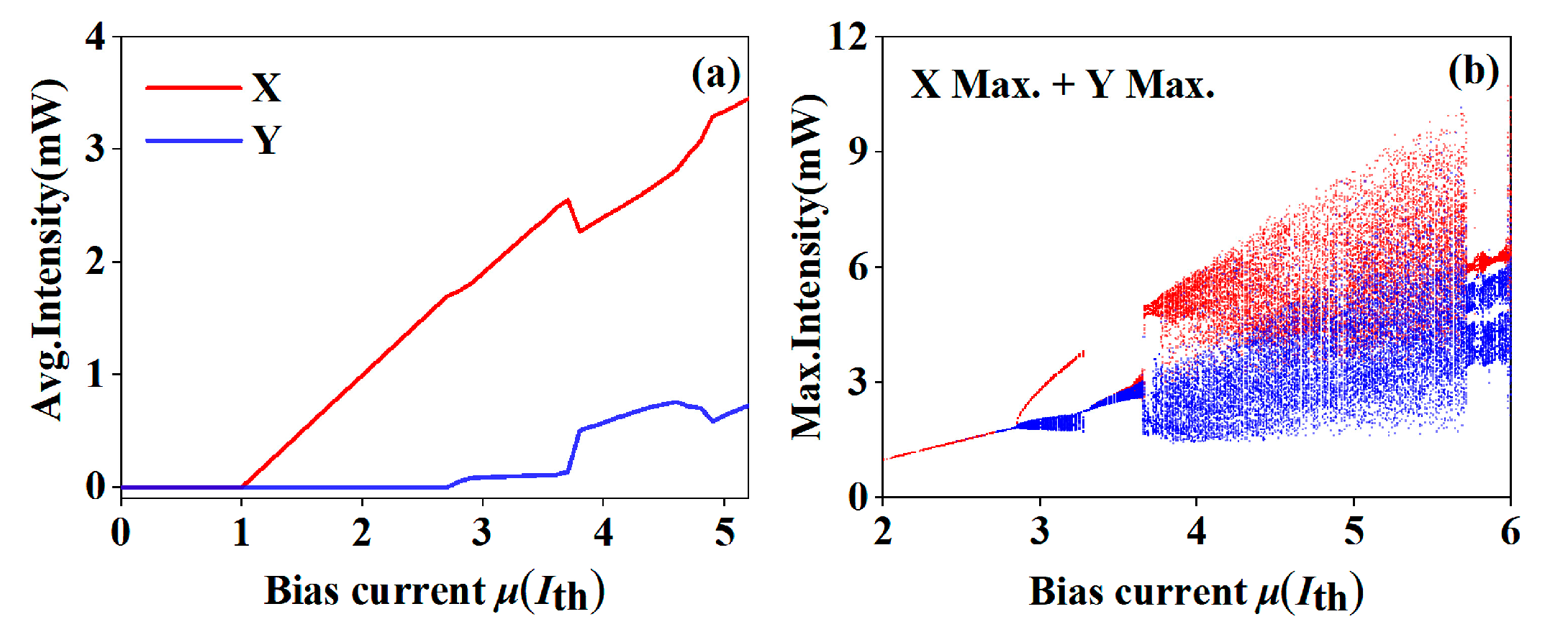
3.1. Basic Characteristics of Polarization Chaos from Free-Running VCSEL

First, we analyzed the P-I characteristics of the free-running VCSEL. As shown in Figure 2a, the red and blue lines represent the P-I curves of the XP and YP mode outputs, respectively. Evidently, the XP mode begins to oscillate when the bias current μ is at the threshold (Ith). The corresponding average intensities increase with the bias current μ. On the other hand, the YP mode cannot be observed until μ = 2.8. In the range of 2.8 < μ < 5.2, both XP and YP modes exist. Figure 2b shows the bifurcation diagram of the local maximum of the intensity time series of the XP and YP modes as a function of the normalized bias current. We can determine that with an increase in μ, the VCSEL undergoes a transition from periodic output into a chaotic regime. Further observation can find that in the range of 3.8 < μ < 5.7, both XP and YP modes chaotically oscillate at the same time.
Based on the above, we set the normalized bias current μ to be 5. Figure 3 shows the time series, frequency spectra and optical spectra of the VCSEL1 XP and YP modes. The black solid lines in the frequency spectra and optical spectra are the associated fitting curves. The time series (Figure 3a-1,b-1) show that the polarization chaos exhibits random fluctuations with large amplitudes, indicating that the lasers are in a chaotic state. The intensity fluctuations of the XP mode are higher than that of the YP mode because the XP mode has been dominant, as shown in Figure 2a. From the frequency spectra (Figure 3a-2,b-2), we can calculate the chaos bandwidth of the XP and YP modes to be 10.07 GHz and 14.25 GHz, respectively. Here, the chaotic bandwidth is defined as the range between the direct current component and the frequency containing 80% of energy [18]. The optical spectra (Figure 3a-3,b-3) show both polarization modes are in single mode.

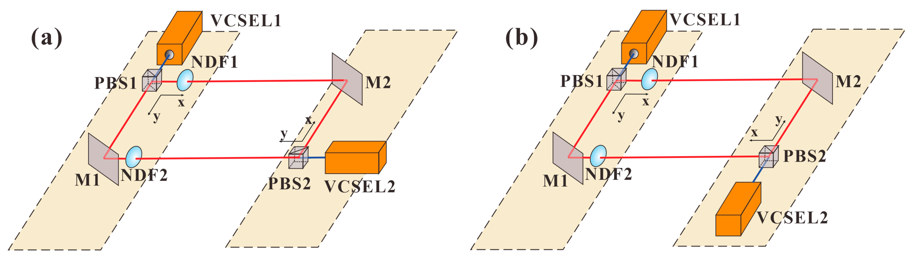
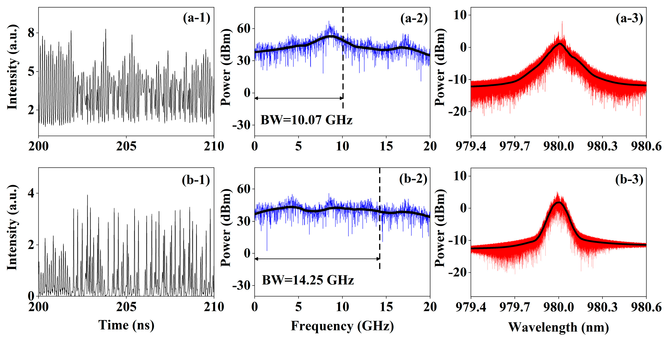
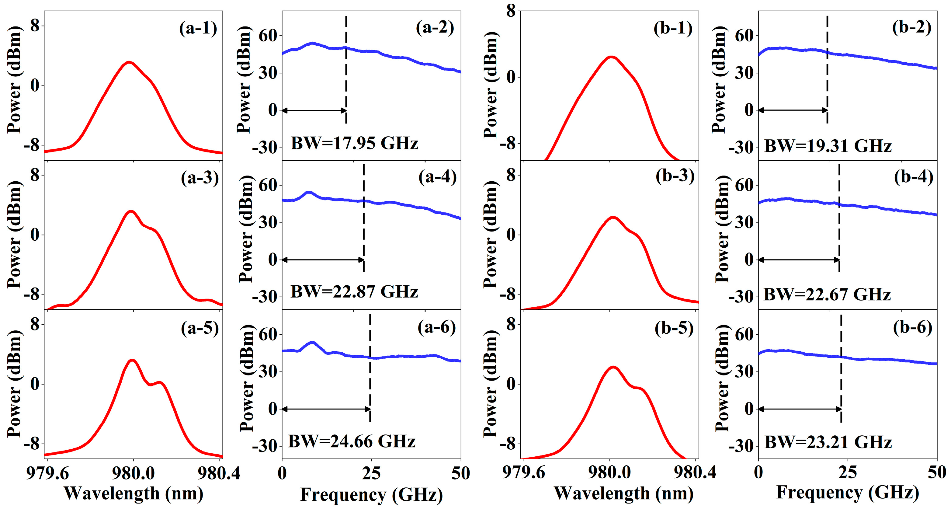
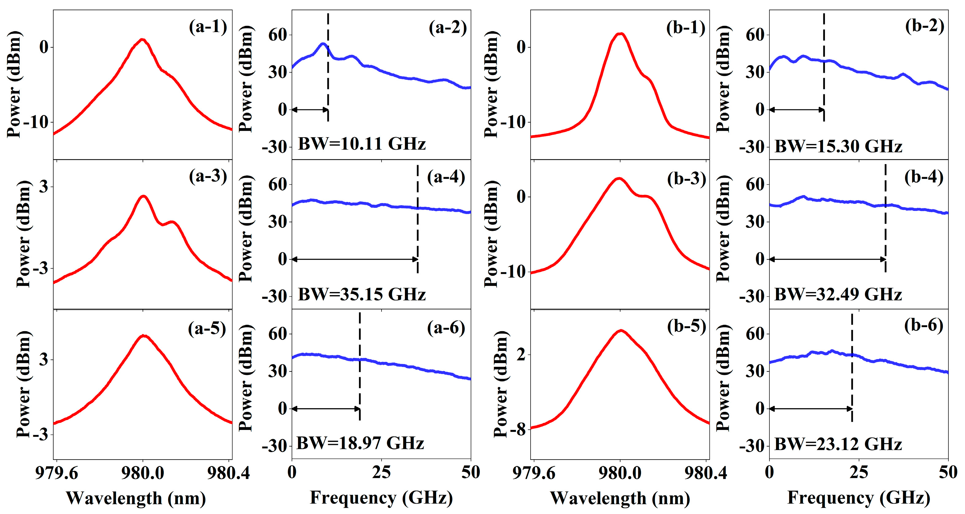
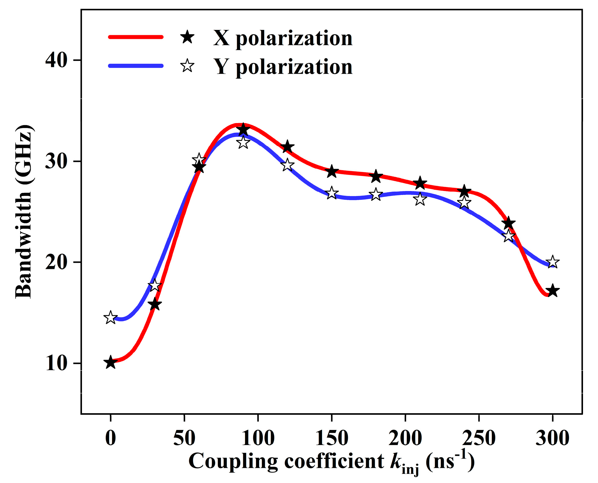
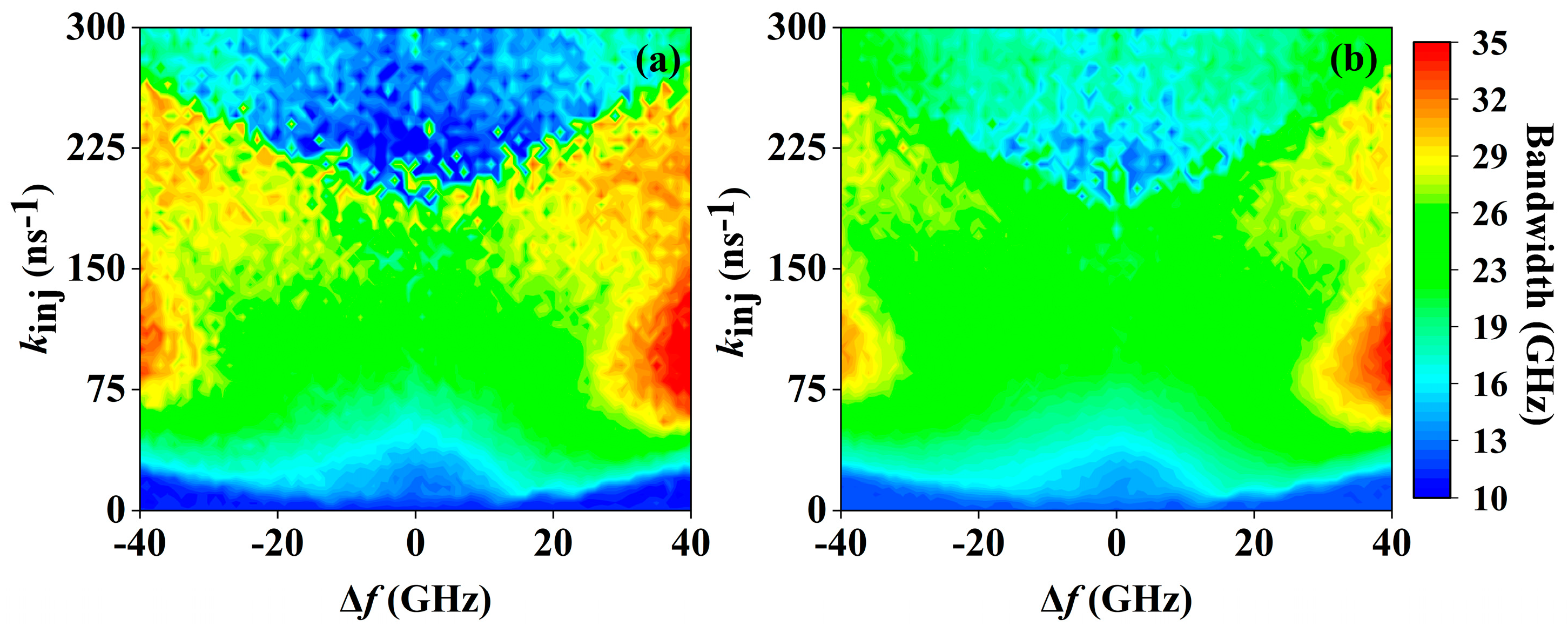
3.2. Enhanced Polarization Chaos Bandwidth by Parallel Injection

In this subsection, we investigate the effects of frequency detuning Δf and coupling coefficient kinj on the polarization chaos bandwidth in parallel injection. Figure 4 shows typical examples of the optical spectra and frequency spectra of the VCSEL1 XP and YP modes when the frequency detuning is set at 20 GHz, 30 GHz and 40 GHz. In this case, kinj = 50 ns−1 and other parameter values are the same as that mentioned before. From the optical spectra of the XP mode (Figure 4a-1,a-3,a-5), it can be seen that injection light excites frequency oscillations by beating with the original chaotic oscillation. As frequency detuning increases, the excited oscillation begins to move away from the relaxation frequency. The frequency spectra of the XP mode (Figure 4a-2,a-4,a-6) show that the optical frequency components grow as a result of the frequency beating of the two chaotic signals. The energy is transferred progressively from the relaxation frequency to the high frequency. By increasing the frequency detuning, the chaotic bandwidth of the XP mode can be increased from 17.95 GHz to 24.66 GHz. Therefore, it can be indicated that the mutual coupling between the high-frequency oscillation and the original chaotic oscillation enhances the bandwidth of the polarization chaos. Similar to the XP mode, the bandwidth enhancement of the YP mode is caused by the same factors.
To further explore the effects of frequency detuning Δf on the polarization chaos bandwidth of VCSEL1, we changed the frequency detuning in the range from 0 GHz to 40 GHz. Figure 5 gives the trend of the polarization chaos bandwidth changing for the XP and YP modes with the frequency detuning Δf when the coupling coefficient kinj = 50 ns−1. The stars represent the specific bandwidth values, and the solid lines represent the curve where we fit the bandwidth values. In this case, we discovered that the chaotic bandwidth of two modes increases with increasing frequency detuning Δf, but then starts to converge when the frequency detuning Δf > 30 GHz. This can be interpreted as meaning that, on the one hand, increasing the frequency detuning helps to enhance the high-frequency components in frequency spectra. On the other hand, the increase in frequency detuning will cause the excited oscillation to move away from the relaxation frequency. Once the frequency detuning is large enough, the frequency of the excitation oscillation will exceed the maximum frequency of the original chaotic oscillation, resulting in their inability to couple. In addition, the bandwidth of the YP mode is larger than that of the XP mode when the Δf = 0 GHz, but the bandwidth of the XP mode begins to surpass that of the YP mode when the frequency detuning Δf > 30 GHz. This is caused by the difference in the original spectral profiles of the XP and YP modes. YP mode has a wider 3dB line width, whereas XP mode has a wider spectral range.
Next, we discuss the effects of the coupling coefficient kinj on the polarization chaos bandwidth under the determined frequency detuning. In this simulation, we fixed the frequency detuning at 40 GHz where the highest chaos bandwidth can be found in Figure 5. Figure 6 shows typical optical spectra and frequency spectra of VCSEL1 XP and YP modes when the coupling coefficient is set at 10 ns−1, 80 ns−1 and 300 ns−1. When the coupling coefficient kinj increases from 10 ns−1 to 80 ns−1, the enhanced beat frequency effect between the two chaotic signals leads to the uniform gain of new frequency components in the optical spectrum (Figure 6a-1,a-3). It leads to the enhancement of energy located in low-frequency and high-frequency components (Figure 6a-2,a-4). When the coupling coefficient kinj = 300 ns−1, the laser enters the injection-locked state, causing the excitation oscillations to be suppressed and a decrease in bandwidth, as shown in Figure 6a-5. The bandwidth variation in the YP mode is caused by the same factors as the XP mode.
Figure 7 depicts the trend of the polarization chaos bandwidth with the coupling coefficient of the VCSEL1 XP and YP modes. Specifically, we set the coupling coefficient kinj in the range from 0 ns−1 to 300 ns−1 with the frequency detuning Δf = 40 GHz. Similar to Figure 5, the stars also represent the specific bandwidth values, and the solid lines represent the fitted bandwidth curve. In this case, we discovered that the chaotic bandwidth of the XP and YP modes initially increases with the coupling coefficient, reaching a maximum value with the coupling coefficient kinj = 80 ns−1. Enhanced beat frequency effect and relaxation frequency enhancement are the main reasons for the bandwidth improvement of the chaotic signal. Then, the chaos bandwidth undergoes a slow decreasing process until the coupling coefficient kinj > 250 ns−1. At this point, the laser begins to enter the injection-locked state. It can be explained that the increase in coupling coefficient will strengthen the injection locking effect. Once the coupling coefficient is large enough, VCSEL2 will be locked by VCSEL1. Moreover, when the coupling coefficient kinj = 0 ns−1, YP mode has a wider bandwidth than XP mode. However, when the coupling coefficient kinj > 60 ns−1, the bandwidth of the XP mode begins to surpass that of the YP mode, which continues until the coupling coefficient kinj > 270 ns−1. As explained before, the reason is related to the original spectral profiles of the XP and YP modes.
Finally, we give the mapping diagrams of polarization chaos bandwidth for the VCSEL1 XP and YP modes as a function of the coupling coefficient kinj and frequency detuning Δf, as shown in Figure 8. The bandwidth variation of the XP and YP modes is almost symmetric in terms of positive and negative frequency detuning. When 10 ns−1 < kinj < 80 ns−1 and Δf varies in the range of 30 GHz < |Δf| < 40 GHz, the chaotic bandwidth of both XP and YP modes increases sharply. The XP mode chaos bandwidth reaches a maximum of 35.15 GHz when the coupling coefficient kinj = 80 ns−1 and the frequency detuning Δf = 40 GHz, as shown in Figure 8a. The YP mode also has the largest bandwidth at this point, reaching 32.94 GHz, as shown in Figure 8b. After achieving the maximum, the band width variation decreases with kinj. Therefore, it can be indicated that with the increase in the coupling coefficient, the frequency components will be redistributed and uniformly gained, but the injection locking effect will also be strengthened. Injection locking will happen when the coupling coefficient kinj > 200 ns−1, whereas increasing the frequency detuning of the two lasers will release this locking effect. Notice that the coupling coefficient necessary for injection locking varies for different frequency detuning.

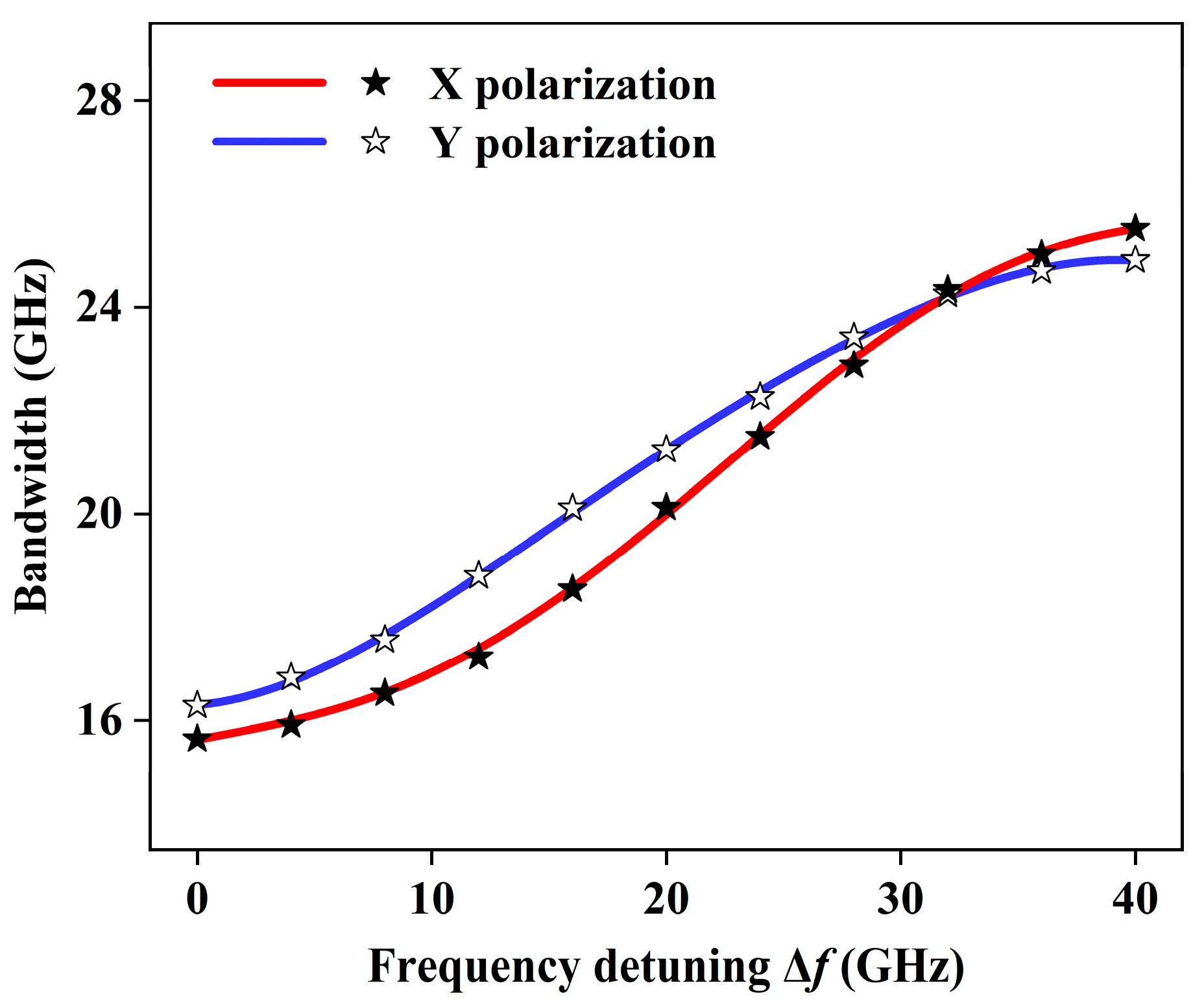
3.3. Enhanced Polarization Chaos Bandwidth by Orthogonal Injection

Additionally, we investigate the effect of frequency detuning and coupling coefficient on the bandwidth of polarization chaos in the scenario of orthogonal injection. Figure 9 shows the mapping diagrams of the bandwidth for the VCSEL1 XP and YP modes as a function of the coupling coefficient kinj and frequency detuning Δf. It can be seen that the broadband is concentrated in the range of 200 ns−1 < kinj < 240 ns−1, while Δf varies in the range of 30 GHz < |Δf| < 40 GHz. Compared with parallel injection, orthogonal injection requires a larger coupling coefficient. In addition, it is of interest to find that the injection locking range of orthogonal injection is also different from that of parallel injection. As shown in Figure 9a, the chaotic light of the XP mode only enters the injection-locked state near zero frequency detuning or in the case of positive detuning, while the chaotic light of the YP mode only enters the injection-locked state near zero frequency detuning or in the case of negative detuning. This is due to the fact that the average intensities of the XP and YP modes differ significantly, and the XP mode light has a larger energy than YP mode light. In the case of positive detuning, the XP mode light requires a high coupling coefficient to obtain a broadband chaotic signal. In contrast, the YP mode can achieve a broadband chaotic signal through a low coupling coefficient.
Finally, we obtain the maximum values of the polarization chaos bandwidth that can be achieved in both modes. The chaos bandwidth of the VCSEL1 XP mode reaches the maximum of 32.96 GHz when the coupling coefficient kinj = 225 ns−1 and the frequency detuning Δf = 40 GHz. The chaos bandwidth of the VCSEL1 YP mode obtained a value of 31.47 GHz when the coupling coefficient kinj = 220 ns−1 and the frequency detuning Δf = 40 GHz. Compared to parallel injection, the maximum bandwidth value that can be achieved by orthogonal injection is slightly lower.

4. Discussion

VCSELs have several advantages over edge-emitting semiconductor lasers, including low power consumption, simple packaging, single longitudinal mode operation, a low threshold current and high reliability. Compared to conventional semiconductor lasers that require external disruption to enter chaotic oscillations [17,18,19,20,21,22,23], free-running VCSELs can generate chaotic signals directly without external perturbation. This simple structure eliminates the periodicity in the chaotic source, enhancing the security of chaotic systems. Thus, free-running VCSELs are a promising source of secure and broadband chaotic signals. Moreover, our research demonstrates that chaotic signals above 30 GHz can be obtained in each of the polarization modes of two VCSELs under the appropriate frequency detuning and coupling coefficient. Therefore, it is expected to concurrently generate multiple, secure and broadband chaotic signals.

5. Conclusions

We have numerically investigated broadband polarization chaos generation using mutually coupled free-running 980 nm VCSELs. Through increasing the bias current, we guarantee the free-running VCSEL work at a chaotic state. Based on this, we studied the influence of frequency detuning and coupling coefficient on the bandwidth of polarization chaos in the cases of parallel and orthogonal injection. The beating frequency between two polarization chaos leads to a uniform distribution of energy over the frequency components, which is the main physical mechanism to achieve the bandwidth enhancement. Final simulation results show that broadband chaos with a bandwidth of sub-40 GHz can be obtained in each of the polarization modes of VCSEL with an appropriate frequency detuning and coupling coefficient. We expect such a simple approach can provide a secure and broadband chaotic signal source for random number generation, secure communications, ranging lidars and other technologies.

Author Contributions

Conceptualization, P.L.; methodology, P.L. and H.B.; writing—original draft preparation, P.L. and H.B; writing—review and editing, P.L., H.B., X.Z., Z.J., L.M., B.X. and K.A.S.; supervision, Y.W.; funding acquisition, P.L., Y.Q. and Y.W. All authors have read and agreed to the published version of the manuscript.

Funding

National Natural Science Foundation of China under Grants (61927811, 62175177 and U19A2076); Program for Guangdong Introducing Innovative and Entrepreneurial Teams; Stability Program of Science and Technology on Communication Security Laboratory (2022); Sichuan Science and Technology Program (2022YFG0330).

Institutional Review Board Statement

Not applicable.

Informed Consent Statement

Not applicable.

Data Availability Statement

Not applicable.

Conflicts of Interest

The authors declare no conflict of interest.

References

  1. Uchida, A.; Amano, K.; Inoue, M.; Hirano, K.; Naito, S.; Someya, H.; Oowada, I.; Kurashige, T.; Shiki, M.; Yoshimori, S.; et al. Fast physical random bit generation with chaotic semiconductor lasers. Nat. Photonics 2008, 2, 728–732. [Google Scholar] [CrossRef]
  2. Kanter, I.; Aviad, Y.; Reidler, I.; Cohen, E.; Rosenbluh, M. An optical ultrafast random bit generator. Nat. Photonics 2010, 4, 58–61. [Google Scholar] [CrossRef]
  3. Hirano, K.; Yamazaki, T.; Morikatsu, S.; Okumura, H.; Aida, H.; Uchida, A.; Yoshimori, S.; Yoshimura, K.; Harayama, T.; Davis, P. Fast random bit generation with bandwidth-enhanced chaos in semiconductor lasers. Opt. Express 2010, 18, 5512–5524. [Google Scholar] [CrossRef]
  4. Li, N.; Kim, B.; Chizhevsky, V.; Locquet, A.; Bloch, M.; Citrin, D.; Pan, W. Two approaches for ultrafast random bit generation based on the chaotic dynamics of a semiconductor laser. Opt. Express 2014, 22, 6634–6646. [Google Scholar] [CrossRef]
  5. Li, P.; Guo, Y.; Guo, Y.; Fan, Y.; Guo, X.; Liu, X.; Shore, K.A.; Dubrova, E.; Xu, B.; Wang, Y.; et al. Self-balanced real-time photonic scheme for ultrafast random number generation. APL Photonics 2018, 3, 061301. [Google Scholar] [CrossRef]
  6. Masoller, C. Anticipation in the synchronization of chaotic semiconductor lasers with optical feedback. Phys. Rev. Lett. 2001, 86, 2782. [Google Scholar] [CrossRef] [Green Version]
  7. Argyris, A.; Syvridis, D.; Larger, L.; Annovazzi-Lodi, V.; Colet, P.; Fischer, I.; Garcia-Ojalvo, J.; Mirasso, C.R.; Pesquera, L.; Shore, K.A. Chaos-based communications at high bit rates using commercial fibre-optic links. Nature 2005, 438, 343–346. [Google Scholar] [CrossRef]
  8. Hong, Y.; Lee, M.W.; Paul, J.; Spencer, P.S.; Shore, K.A. GHz bandwidth message transmission using chaotic vertical-cavity surface-emitting lasers. J. Light. Technol. 2009, 27, 5099–5105. [Google Scholar] [CrossRef]
  9. Ke, J.; Yi, L.; Xia, G.; Hu, W. Chaotic optical communications over 100-km fiber transmission at 30-Gb/s bit rate. Opt. Lett. 2018, 43, 1323–1326. [Google Scholar] [CrossRef]
  10. Jiang, N.; Zhao, A.; Xue, C.; Tang, J.; Qiu, K. Physical secure optical communication based on private chaotic spectral phase encryption/decryption. Opt. Lett. 2019, 44, 1536–1539. [Google Scholar] [CrossRef]
  11. Lin, F.Y.; Liu, J.M. Chaotic lidar. IEEE J. Sel. Top. Quantum Electron. 2004, 10, 991–997. [Google Scholar] [CrossRef]
  12. Piracha, M.U.; Nguyen, D.; Mandridis, D.; Yilmaz, T.; Ozdur, I.; Ozharar, S.; Delfyett, P.J. Range resolved lidar for long distance ranging with sub-millimeter resolution. Opt. Express 2010, 18, 7184–7189. [Google Scholar] [CrossRef] [Green Version]
  13. Cheng, C.H.; Chen, C.Y.; Chen, J.D.; Pan, D.K.; Ting, K.T.; Lin, F.Y. 3D pulsed chaos lidar system. Opt. Express 2018, 26, 12230–12241. [Google Scholar] [CrossRef] [PubMed]
  14. Mork, J.; Tromborg, B.; Mark, J. Chaos in semiconductor lasers with optical feedback: Theory and experiment. IEEE J. Quantum Electron. 1992, 28, 93–108. [Google Scholar] [CrossRef]
  15. Wang, A.; Wang, Y.; He, H. Enhancing the bandwidth of the optical chaotic signal generated by a semiconductor laser with optical feedback. IEEE Photon. Technol. Lett. 2008, 20, 1633–1635. [Google Scholar] [CrossRef]
  16. Sciamanna, M.; Shore, K.A. Physics and applications of laser diode chaos. Nat. Photonics 2015, 9, 151–162. [Google Scholar] [CrossRef] [Green Version]
  17. Uchida, A.; Heil, T.; Liu, Y.; Davis, P.; Aida, T. High-frequency broad-band signal generation using a semiconductor laser with a chaotic optical injection. IEEE J. Quantum Electron. 2003, 39, 1462–1467. [Google Scholar] [CrossRef]
  18. Lin, F.; Liu, J. Nonlinear dynamical characteristics of an optically injected semiconductor laser subject to optoelectronic feedback. Opt. Commun. 2003, 221, 173–180. [Google Scholar] [CrossRef]
  19. Schires, K.; Gomez, S.; Gallet, A.; Duan, G.H.; Grillot, F. Passive chaos bandwidth enhancement under dual-optical feedback with Hybrid III–V/Si DFB laser. IEEE J. Sel. Top. Quantum Electron. 2017, 23, 1801309 . [Google Scholar] [CrossRef] [Green Version]
  20. Bouchez, G.; Uy, C.H.; Macias, B.; Wolfersberger, D.; Sciamanna, M. Wideband chaos from a laser diode with phase-conjugate feedback. Opt. Lett. 2019, 44, 975–978. [Google Scholar] [CrossRef] [Green Version]
  21. Zhao, A.; Jiang, N.; Liu, S.; Xue, C.; Tang, J.; Qiu, K. Wideband complex-enhanced chaos generation using a semiconductor laser subject to delay-interfered self-phase-modulated feedback. Opt. Express 2019, 27, 12336–12348. [Google Scholar] [CrossRef] [PubMed] [Green Version]
  22. Hong, Y. Flat broadband chaos in mutually coupled vertical-cavity surface-emitting lasers. IEEE J. Sel. Top. Quantum Electron. 2015, 21, 652–658. [Google Scholar] [CrossRef]
  23. Chai, M.; Qiao, L.; Zhang, M.; Wang, A.; Yang, Q.; Zhang, J.; Wang, T.; Gao, S. Simulation of monolithically integrated semiconductor laser subject to random feedback and mutual injection. IEEE J. Quantum Electron. 2020, 56, 2001008. [Google Scholar] [CrossRef]
  24. Zhang, W.L.; Pan, W.; Luo, B.; Wang, M.Y.; Zou, X.H. Synchronization performance comparison of vertical-cavity surface-emitting lasers with two different feedback chaos schemes. Semicond. Sci. Technol 2005, 20, 979. [Google Scholar] [CrossRef]
  25. Rontani, D.; Locquet, A.; Sciamanna, M.; Citrin, D.S.; Ortin, S. Time-delay identification in a chaotic semiconductor laser with optical feedback: A dynamical point of view. IEEE J. Quantum Electron. 2009, 45, 879–1891. [Google Scholar] [CrossRef]
  26. Soriano, M.C.; García-Ojalvo, J.; Mirasso, C.R.; Fischer, I. Complex photonics: Dynamics and applications of delay-coupled semiconductors lasers. Rev. Mod. Phys 2013, 85, 421. [Google Scholar] [CrossRef] [Green Version]
  27. Virte, M.; Panajotov, K.; Thienpont, H.; Sciamanna, M. Deterministic polarization chaos from a laser diode. Nat. Photonics 2013, 7, 60–65. [Google Scholar] [CrossRef] [Green Version]
  28. Virte, M.; Panajotov, K.; Sciamanna, M. Bifurcation to nonlinear polarization dynamics and chaos in vertical-cavity surface-emitting lasers. Phys. Rev. Appl. 2013, 87, 013834. [Google Scholar] [CrossRef]
  29. Mu, P.; Pan, W.; Li, N. Analysis and characterization of chaos generated by free-running and optically injected VCSELs. Opt. Express 2018, 26, 15642–15655. [Google Scholar] [CrossRef]
  30. Martin-Regalado, J.; Prati, F.; San Miguel, M.; Abraham, N. Polarization properties of vertical-cavity surface-emitting lasers. IEEE J. Quantum Electron. 1997, 33, 765–783. [Google Scholar] [CrossRef] [Green Version]
Figure 1. Schematic for polarization chaos in two mutually coupled VCSELs in two scenarios of (a) parallel injection and (b) orthogonal injection. VCSEL1 and VCSEL2, vertical-cavity surface-emitting lasers; PBS1 and PBS2, polarizing beam splitters; NDF1 and NDF2, neutral density filters; M1 and M2, mirrors.
Photonics 10 00219 g001
Figure 2. (a) Average output intensity of the XP (red line) and YP (blue line) modes as a function of bias current μ; (b) Bifurcation diagram of the local maximum of the XP (red dots) and YP (blue dots) output intensity versus the bias current μ.
Photonics 10 00219 g002
Figure 3. The time series, frequency spectra, and optical spectra for (a-1a-3) XP mode and (b-1b-3) YP mode of the free-running VCSEL1 when the bias current is 5.
Photonics 10 00219 g003
Figure 4. The optical spectra and frequency spectra of the (a-1a-6) XP mode and (b-1b-6) YP mode of the VCSEL1. (a-1,a-2) and (b-1,b-2) kinj = 50 ns−1 and Δf = 20 GHz; (a-3,a-4) and (b-3,b-4) kinj = 50 ns−1 and Δf = 30 GHz; (a-5,a-6) and (b-5,b-6) kinj = 50 ns−1 and Δf = 40 GHz.
Photonics 10 00219 g004
Figure 5. The variation of polarization chaos bandwidth for XP and YP modes of VCSEL1 with the frequency detuning.
Photonics 10 00219 g005
Figure 6. The optical spectra and frequency spectra of the (a-1a-6) XP mode and (b-1b-6) YP mode of the VCSEL1. (a-1,a-2) and (b-1,b-2) kinj = 10 ns−1 and Δf = 40 GHz; (a-3,a-4) and (b-3,b-4) kinj = 80 ns−1 and Δf = 40 GHz; (a-5,a-6) and (b-5,b-6) kinj = 300 ns−1 and Δf = 40 GHz.
Photonics 10 00219 g006
Figure 7. The variation of polarization chaos bandwidth for XP and YP modes of VCSEL1 with the coupling coefficient.
Photonics 10 00219 g007
Figure 8. Polarization chaos bandwidth of (a) XP mode and (b) YP mode of VCSEL1 in parallel injection as a function of the coupling coefficient kinj and frequency detuning Δf.
Photonics 10 00219 g008
Figure 9. Polarization chaos bandwidth of (a) XP mode and (b) YP mode of VCSEL1 in orthogonal injection as a function of the coupling coefficient kinj and frequency detuning Δf.
Photonics 10 00219 g009
Table 1. VCSEL parameters and values used in simulation.
ParameterSymbolValue
Field decay rateκ300 ns−1
Linewidth enhancement factorα3
Linear dichroismγa0.5 ns−1
Linear birefringenceγp30 ns−1
Carrier decay rateγN1 ns−1
Spin-flip relaxation rateγS50 ns−1
coupling coefficient kinj0~300 ns−1
Propagation time delayτ3 × 10⁻⁹ s
Bias current μ1~6
Disclaimer/Publisher’s Note: The statements, opinions and data contained in all publications are solely those of the individual author(s) and contributor(s) and not of MDPI and/or the editor(s). MDPI and/or the editor(s) disclaim responsibility for any injury to people or property resulting from any ideas, methods, instructions or products referred to in the content.

