Abstract
Laser plasma acceleration has made remarkable progress in the last few decades, but it also faces many challenges. Although the high gradient is a great potential advantage, the beam quality of the laser accelerator has a certain gap, or it is different from that of traditional accelerators. Therefore, it is important to explore and utilize its own features. In this article, some recent research progress on laser proton acceleration and its irradiation application, which was carried out on the compact laser plasma accelerator (CLAPA) platform at Peking University, have been introduced. By combining a TW laser accelerator and a monoenergetic beamline, proton beams with energies of less than 10 MeV, an energy spread of less than 1%, and with several to tens of pC charge, have been stably produced and transported in CLAPA. The beamline is an object–image point analyzing system, which ensures the transmission efficiency and the energy selection accuracy for proton beams with large initial divergence angle and energy spread. A spread-out Bragg peak (SOBP) is produced with high precision beam control, which preliminarily proved the feasibility of the laser accelerator for radiotherapy. Some application experiments based on laser-accelerated proton beams have also been carried out, such as proton radiograph, preparation of graphene on SiC, ultra-high dose FLASH radiation of cancer cells, and ion-beam trace probes for plasma diagnosis. The above applications take advantage of the unique characteristics of laser-driven protons, such as a micron scale point source, an ultra-short pulse duration, a wide energy spectrum, etc. A new laser-driven proton therapy facility (CLAPA II) is being designed and is under construction at Peking University. The 100 MeV proton beams will be produced via laser–plasma interaction by using a 2-PW laser, which may promote the real-world applications of laser accelerators in malignant tumor treatment soon.
1. Introduction
A particle accelerator is a device that uses the electromagnetic field to accelerate charged particles to a high energy, which is one of the most important scientific tools to study basic nuclear physics and to explore the deep structure of space and time. In the meantime, the accelerators also play an important role in promoting social development and improving the quality of people’s lives. More than 30 thousand accelerators are in operation around the world in the field of medicine (oncology therapy and radioisotope production), national defense, and industrial production (ion implanters). However, due to the restriction of the vacuum breakdown threshold, the acceleration gradient of the conventional accelerators is limited to 100 MV/m. The huge volume and the expensive construction costs have become the bottleneck of the accelerators to higher energy development. Therefore, the new principle of acceleration with lasers, which was first proposed by Tajima and Dawson in 1979, has been extensively studied during the last few decades in order to offer an alternative [1].
With the continuous development of high-power laser technology [2,3], the intensity of a focused laser pulse can exceed the relativistic optics regime, and even reach 1022 W/cm2. When such an ultra-intense laser pulse interacts with plasma of different parameters, it can either excite the wakefield [4] (accelerating electrons) or the electrostatic sheath field [5] (accelerating ions) at a micron scale, and the acceleration gradient is as high as GV/m to TV/m. Laser plasma acceleration is expected to achieve the miniaturization of accelerators due to the acceleration gradient that exceeds that of the conventional accelerators by three orders of magnitude, and has attracted extensive attention. Up to now, the 8 GeV [6] quasi mono-energetic electron beam and the proton beam with the highest energy of nearly 100 MeV [7] have been successfully demonstrated using laser–plasma acceleration. At present, laser-accelerated protons have initially been applied in the fields of biomedicine, material science, high-energy-density physics, and so on [8]. With the development of high-repetition-rate Petawatt (PW) laser technology [9], we can now envision a new generation of accelerators with many applications [10,11], especially for cancer therapy [12,13,14], in the near future.
It should be noted that, compared with electron acceleration, it is more challenging for laser ion acceleration to reach a high beam quality, due to the quick diffusion of hot electrons, which work as the energy transfer medium between the lasers and the ions [15,16], as well as the variety of instabilities during the laser–solid target interaction process [17,18]. Except for the maximum energy of the accelerated ions, the major issues are the emittance, the energy spread, the charge, and especially the reliability-availability-maintainability-inspectability (RAMI), which are necessary conditions to raise the laser “acceleration” to “accelerator” for applications. Irradiation research based on this new type of proton beam is also challenging and innovative; on one hand, it is necessary to optimize the beam transmission and control; on the other hand, it is also necessary to explore new irradiation phenomena and to expand the application fields. Here, we introduce some research progresses on laser proton acceleration and its irradiation application at Peking University. Most of the work below was carried out on the compact laser plasma accelerator (CLAPA) platform.
2. Experimental Demonstration of a Laser Proton Accelerator with Accurate Beam Control through Image-Relaying Transport
A compact laser plasma accelerator (CLAPA) that can stably produce and transport protons with different energies of less than 10 MeV, an energy spread of less than 1%, and with several to tens of pC charge, has been demonstrated [19]. The high-current proton beam with a continuous energy spectrum and a large divergence angle [20,21] is generated by using a high-contrast laser and micron thickness solid targets, which is later collected, analyzed, and refocused by an image-relaying beamline by using a combination of quadrupole and bending electromagnets [22,23]. It eliminates the inherent defects of the laser-driven beams, realizes the precise manipulation of the proton beams with reliability, and takes the first step towards applications of this new generation of accelerators.
In the experiment, a p-polarized laser pulse with 1.8 J of energy and 30 fs duration was focused onto a 1.2 μm thickness plastic target by using a f/3.5 off-axis parabola at an incident angle of 30 degrees with respect to the target’s normal direction. The on-target intensity was 8 × 10¹⁹ W/cm2. The laser contrast was 10−10 at 40 ps before the main pulse, which was achieved by using a cross-polarized wave generation (XPW). The high energy protons were mainly generated by the target normal sheath acceleration (TNSA) mechanism [15,24]. In the TNSA, the hot electrons are driven out of the solid density target due to the ponderomotive force of the laser, forming a sheath field with a gradient of up to TV/m. The ions (mainly protons with the highest charge-to-mass ratio) on the surfaces of the target are accelerated accordingly to high energy within tens of micrometers. Due to the ultra-short transient acceleration process, the proton beam has the characteristics of a high short pulse duration (ps-ns), a high peak current, a large divergence angle (tens of degrees), and an exponential decay energy spectrum.
A Thomson spectrometer was placed 14 cm behind the target in order to measure the energy spectrum of the protons. One typical energy spectrum is shown by the black curve in Figure 1a. During the beamline experiment, this Thomson spectrometer was replaced by a quadrupole triplet lens. Then, an insertable radiochromic film (RCF) stack that was positioned 4 cm behind the target was used to measure the original spatial and energy distribution of the protons [25]. After the ionizing radiation, the active material inside of the RCF undergoes polymerization and changes its color from transparent to opaque, with the degree of color conversion that is proportional to the absorbed dose. Figure 1b shows the typical images of one RCF stack, where three types of RCFs (HD-V2, MD-V3, and EBT-3) were superimposed. The corresponding energy spectrum that was extracted from the RCF stack is shown in Figure 1a (pink dots), which is quite consistent with the Thomson spectrometer measurement.
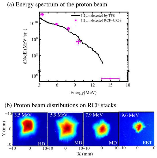
Figure 1.
(a) The typical energy spectrum measured by the Thomson spectrometer (black curve) and the RCF stack (pink dots) based on a 1.2 μm plastic target. (b) Images in one RCF stack, where three types of RCFs (HD-V2, MD-V3, and EBT-3) were used.
After detecting the characteristics of the laser-driven proton beams, a magnet lattice consisting of quadruple and bending electromagnets was specially designed, as shown in Figure 2. The protons are first collected and focused by a quadrupole triplet lens that was placed 19 cm behind the target with a collection angle of ±50 mrad [26], then analyzed by a 45° sector magnet, and finally refocused by a quadrupole doublet lens onto the irradiation platform. The beamline incorporated three beam profile detectors (the first two using scintillators and the third using micro-channel plate (MCP)), which were located near the focal plane of the triplet lens as BPD#1, the image point of the sector magnet as BPD #2, and at the irradiation point as BPD#3, respectively. The flexibility of the electromagnets between the slits and the BPDs is crucial in order to enable effective beam diagnostics without impacting the applications.
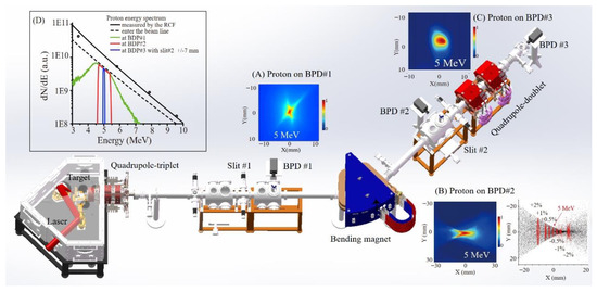
Figure 2.
Layout of the acceleration chamber and beamline for CLAPA. The proton beam is accelerated by using a high-contrast laser and micro-thickness foil; it is then focused by a quadrupole triplet lens, analyzed by a bending electromagnet, and refocused by a quadrupole doublet lens with selected energy onto the irradiation platform. The inserted graph (A) Experimental result of the 5 MeV proton beam profile at BPD#1 after focusing by the triplet lens. (B) Experimental (left) and simulated (right) spatial distributions of the protons at BPD#2. The red dots in the simulated result, from right to left, represent the protons with energy deviated −2%, −1%, −0.5%, 0%, 0.5%, 1%, and 2% from 5 MeV, respectively. (C) Proton beam distribution at BPD#3, with a 5 MeV central energy and 1% energy spread. (D) Energy spectra of protons at different positions along the beamline. The black solid curve is the original exponentially declining energy spectrum (based on the RCF data shown in Figure 1). The black dashed curve is the actual spectrum entering the beamline within an acceptance angle of ±50 mrad. The green, red, and blue curves are the simulated spectra at the three beam position detectors BPD#1, BPD#2, BPD#3, respectively. The initial beam with a very broad energy spectrum is gradually confined to a 1% energy spread.
Figure 2A shows the experimental result of the proton beam profile on BPD#1 after it was focused by the triplet lens. The focused central energy was set at 5 MeV. The slit#1 was put at the object point of the bending magnet, which could partially screen the unwanted energies, leading to about ±10% energy spread of the beam within a 3 cm2 transverse area. The beam spot distribution that is shown here has a cross shape with a blurred boundary, due to the chromatic aberration and the large acceptance angle of the initial beam. Following this, a 45° sector magnet was used to select the proton energy, under which the protons from the same object point with the same energy and different angular divergence converge to the same image point at the x axis, while the protons with different energies are separated in the x direction. This object-to-image point transport system can remove the influences of a large divergence angle and a large energy chirp of the initial protons at the image point. Figure 2B shows the simulated (right) and the experimental (left) spatial distributions of the proton beam at BPD#2. They both show a bow tie profile with 5 MeV protons at the knot, which indicates that the chromatic aberration in the y direction, and those with energies that deviated from 5 MeV, were dispersed aside. By controlling the opening width of slit#2, which was installed at the image point of the sector magnet, the energy spread of the protons could be precisely controlled. In the end, a quadrupole doublet lens was used to focus the mono-energetic protons to the irradiation point with a desired spot size. Figure 2C shows the experimental spatial distributions of the proton beam at BPD#3 (5 MeV and ±1% energy spread). The final focused beam profile could be adjusted as required, for the quadruple doublet lens had the advantage of controlling the envelopes independently in the x and y directions.
The energy spectrum evolution of the proton beam through the beamline is presented in Figure 2D, which demonstrates how the initial broadband beam energy was gradually confined to ±1% energy spread after each electromagnet. The black curve is the original energy spectrum that was deconvolved from the RCF data that is shown in Figure 1b. The black dashed curve is the energy spectrum entering the beamline that takes the ±50 mrad acceptance angle into account. The green, red, and blue curves are the simulated spectra at BPD#1, BPD#2, and BPD#3, respectively. In the experiment, by varying the width of slit#2 from 3 to 54 mm, the corresponding energy spread was increased from ±0.5 to ±4%, and the final charge was tuned correspondingly. The beam transmission efficiency has been reduced to less than 30% since the first triplet lens. Combined with the subsequent energy selection, the overall beam loss rate was higher than 95%, which is a great waste of energy. Therefore, the subsequent design of the beamline with achromatic ability is very critical. The proton source can also be modified from the beginning of the acceleration. Apart from TNSA which has a better stability, other acceleration mechanisms, such as radiation pressure acceleration (RPA) [27,28] or guided post-acceleration [29,30], should also be adopted, to modulate the proton energy spectrum being more concentrated in the aimed energy.
3. Emittance Measurement along Transport Beamline for Laser-Driven Protons
The particle emittance quantifies the ability to focus and transport a beam and is one of the most important parameters for a beamline [31]. The laser–plasma accelerated proton beam has been characterized by a micron scale point source and a small emittance of less than 0.004 mm mrad [32], indicating that it should be easier to focus and transmit compared to that of the conventional accelerators. However, due to the broad energy spread and the large divergence, its initial ultralow emittance will increase rapidly in the subsequent transmission process. We have systematically measured the emittance of a proton beam that was produced by ultra-intense laser irradiation on a micron-thick flat solid target along the CLAPA transport beamline [33]. An over 3-fold emittance growth was found for the 5 MeV laser-driven protons with an energy spread of ±2% and a divergence of ±20 mrad after being transported 5.9 m in the experiment.
The emittance measurement experiment setup is shown in Figure 3. The laser pulse was focused by an F3.5 OAP onto 5-micron-thick plastic foils at 30° with respect to the target’s normal direction. The originally accelerated TNSA proton beams had exponential decaying energy distribution with a cutoff energy of around 6.5 MeV and a divergence of hundreds of mrad. The protons were first focused by a quadrupole triplet electromagnet with an entrance at 14 cm behind the target, and then the energy that was dispersed by a 45° dipole magnet that was placed 1.2 m behind the triplet. Only those protons with a divergence that was smaller than ±20 mrad (corresponding to rms divergence of about 8.2 mrad) were input into the beamline in the emittance measurement experiment in order to avoid the effect of non-linearity in the applied forces of the magnets on the result. The following three methods were employed: (a) pepper-pot right after the target, (b) a quadrupole scan technique using the magnet triplet, and (c) single-shot emittance measurement with the dipole magnet.
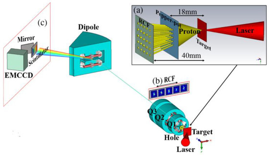
Figure 3.
Setup of the emittance measurement experiment on the CLAPA beamline. Protons are accelerated along the z direction, focused by the electromagnetic quadrupole triplet lens, in which Q1 and Q3 focus in the x direction and Q2 focuses in the y direction, and are dispersed by the dipole magnet in the x direction. The following three methods were employed for the emittance measurement [33]: (a) pepper-pot; (b) quadrupole scan technique; and (c) single-shot emittance measurement after the dipole.
Figure 4 summarizes the emittance measurements for the 5 MeV laser-accelerated proton beam, which was measured at three different positions with the above three methods. The solid curves are the evolution of the emittance, as simulated with the program CST, in which protons with a source size of 50 μm, an energy spread of ±2%, and a divergence of ± 20 mrad were simulated, corresponding to an original emittance . Here, is the normalized root mean square (rms) emittance that was derived in the trace space (x; x′) and is the rms emittance that was derived in the phase space (x; px) [31]. There is clear growth in , both inside of the triplet and in the drift space, which matches the simulation well. The symbols with error bars are the experiment result. We have shown that the initial extremely small emittance at the source point (less than 0.004 mm mrad, as measured by Cowan [32]) increases by more than one order of magnitude after a few centimeters of propagation and remains between 0.04 mm mrad and 0.10 m mrad for the subsequent transport. This conclusion is suitable for the measured protons with ±2% energy spread and ±20 mrad angle in order to meet with the paraxial condition, which means that for the design of a monoenergetic beamline, the laser accelerator can be regarded as the same as the conventional accelerator. However, in order to fully use the laser-accelerated protons, an achromatic beamline with a large acceptance angle is recommended. In this condition, the emittance will increase significantly under the double effects of energy chromatic aberrations and the nonlinear edge field of the magnet components, bringing great challenge to the beamline design.
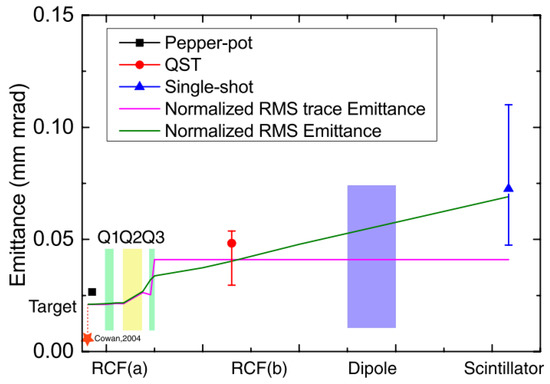
Figure 4.
Emittance values from simulations and experiments. The solid lines are the emittance evolution during transport in simulations. The points with error bars are experimental results.
4. Production of the Spread-Out Bragg Peak (SOBP) by a Tailored Energy Deposition
Compact and low-cost proton radiotherapy is one important application that is expected to be implemented by the laser accelerator. In proton radiotherapy, the parameters of a continuous incident proton beam must be adjusted according to the requirements of the treatment plan, so that the irradiated dose accurately covers the whole three-dimensional volume of a tumor tissue. In other words, the narrow Bragg peak of the monoenergetic protons has to be broadened to the spread-out Bragg peak (SOBP) by combining separate shots at different energies. The SOBP is one of the key technologies of radiotherapy, and it requires high-precision beam control of energy, energy spread, energy spectrum, beam source position, beam spot size, and uniformity, which is a challenge, especially for a laser accelerator.
We have tested this ability by accumulating 203 shots of laser-driven protons with central energies of 3.45 MeV (two shots), 3.66 MeV (four shots), 3.88 MeV (six shots), 4.11 MeV (15 shots), 4.36 MeV (30 shots), 4.62 MeV (146 shots), and an energy spread of ± 3%, then, the total energy range was from 3.35 to 4.76 MeV [34]. We used the CLAPA beamline to select the proton beams from the initial exponentially decaying energy spectra (the dashed black line in Figure 5b) and accumulated them into an ascending energy spectrum (the red curve in Figure 5b), so as to obtain the tailored energy deposition that is required for the SOBP at the irradiation platform.
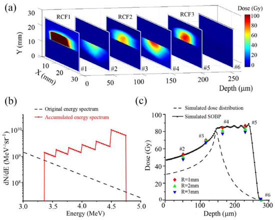
Figure 5.
Production of a spread-out Bragg peak with accumulated proton shots at different energies. (a) Dose distributions at different depths recorded on the RCF stack. The depth shift of the Bragg peak, due to the aluminum foil, is converted to an equivalent depth for the RCF film. (b) The black dashed curve is the original exponentially decaying energy spectrum measured directly behind the foil target in the acceleration chamber. The red curve is the total spectrum of proton beams accumulated to form the SOBP on the irradiation platform. (c) Comparison of the experimental results with a simulated depth profile. The black curve is the accumulated dose distributions of all 203 shots of protons, as simulated using SRIM. The red, green, and blue dots represent the average doses within a 1, 2, and 3 mm radius of the beam center, respectively, at the different depths obtained in the experiment. The black dashed curve represents the expected dose profile if we were to use the exponentially decaying energy spectrum directly. The dose coordinate of the black dashed curve is magnified for ease of comparison, while the shape of the curve is not changed.
A stack of three layers of HD-V2 RCFs was used to record the three-dimensional dose distributions. A 30 μm thick aluminum foil was put in front of the lower half of the first RCF, so that the corresponding Bragg peak energy in each RCF-sensitive layer (the lower part) was shifted. We can see that the dose distributions at different depths of energy deposition are nearly radially symmetric, as shown in Figure 5a. Using a ± 3% energy spread increases the utilization of the proton beams and maintains a radially symmetric proton distribution. It is important to note that the carbon and oxygen ions with the same beam rigidity q2 × E/A were inevitably transported with the same transverse envelope, with the protons in the beamline being composed of only magnetic field components. The penetration depth of the heavy ions was much smaller than that of the protons at the same energy, hence, they could be easily blocked by a thin foil. In Figure 5a, the upper half of the first RCF acts as a shield for these heavy ions, which caused excessive dosage.
Figure 5c shows the calculated dose distribution (the black solid curve) at different depths and the experimental average doses within 1 mm (the red diamond), 2 mm (the green triangle), and 3 mm (the blue triangle) radius of the beam spots. The results show a good fit to the expected depth profile, demonstrating that it is possible to produce a SOBP with a laser accelerator. The black dashed curve in Figure 5c shows the expected dose curve if we were to use the original exponentially decaying spectrum directly (the dashed curve in Figure 5a), for comparison. Hence, tailoring the number of shots for different central energies changes the final dose depth profile, and enables an initially exponentially decaying spectrum in order to satisfy the requirements of the SOBP. The result also shows the potential feasibility of future irradiation based on laser-accelerated proton beams.
5. The Beamline Design for CLAPA Ⅱ
5.1. Achromatic Beamline Design for CLAPA Ⅱ
A new petawatt laser-driven proton therapy facility (CLAPA II) is being designed and constructed by Peking University. In the CLAPA platform that has been introduced above, the proton beams are generated mainly in the TNSA regime in a relatively low laser intensity, and the micrometer thickness targets are used to maintain stable operation. In the new therapy facility, light pressure acceleration (RPA) [27,28], the coherent acceleration of ions by laser (CAIL) [35,36] mechanisms, or in combination with a critical density plasma [37,38,39,40], will be dominant, in order to improve the acceleration efficiency. This is because under the RPA mechanism, the energy of the proton beam is directly proportional to the laser intensity [41,42,43,44], while it is proportional to the half power of the laser intensity in the TNSA mechanism [15,45]. Therefore, as the laser power increases to the PW level, the RPA will demonstrate greater advantages in obtaining higher proton energy. There is an optimal matching parameter between the target and the laser, which is expressed as , where is the normalized amplitude that is related to the laser intensity by , is the critical density, d and are the target thickness and density, respectively. It should be noted that the optimal solid target thickness for a PW laser intensity is still in the nanometer scale, which requires both a high contrast and a steep rising edge of the laser pulse. In CLAPA II, the protons will be produced by using a 2-PW laser to reach the proton energies exceeding 100 MeV. We hope that the construction of this facility will promote the real-world applications of laser accelerators.
The CLAPA II beam transmission system is designed for a 100 MeV proton beam that is produced by PW laser acceleration, and its feasibility is tested through theoretical simulations [46]. It is designed with two transport lines in order to provide both horizontal and vertical irradiation modes, as demonstrated in Figure 6. The length and the bending angle of the horizontal beamline are 12.96 m and 90°, respectively, and for the vertical beamline these values are 22.56 m and 270°, respectively. Compared to the original CLAPA beamline, the new design includes magnets with multiple functions and has several notable advantages, including an improved acceptance angle, achromatic ability, and a better spot uniformity. A locally-achromatic design method with new canted-cosine-theta (CCT) magnets [47] has been used to mitigate the negative effects of the large energy spread that is produced by laser acceleration, and to reduce the overall weight of the vertical beamline. The beamline contains a complete energy selection system, which can reduce the energy spread of the laser-accelerated beam enough to meet the application requirements. The users can select the proton beam energy within the range of 40–100 MeV, which is then transmitted through the rest of the beamline. A beam spot with a diameter of less than 15 mm and an energy spread of less than 5% can be provided at the horizontal and vertical irradiation targets. Each bending element of the beamline is locally achromatic, which allows us to significantly limit the envelope growth of the beam, due to dispersion. The use of CCT magnet technology in the vertical beamline can provide design experience for follow-up work with a superconducting gantry. CLAPA II and the beamline is expected to be operational in the Beijing Laser Accelerator Innovation Center (BLAIC) in 2024.
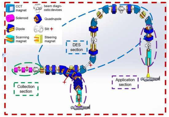
Figure 6.
Layout of CLAPA Ⅱ and its transport system. The overall layout of the beam transport system is in the red dotted box. The different sections of the beam transport system are circled by dashed lines of different colors.
5.2. Designing of Active Plasma Lens for CLAPA Ⅱ
Compared with the traditional beam, the laser-accelerated beam has several different properties. Therefore, in addition to catching up with the parameters and the technologies of the traditional beam, we must also explore new methods for laser-beam transmission and application. The plasma medium has high energy storage and regulation capabilities, which can support extremely high electromagnetic fields, making it a potential candidate for a suitable beam transmission element.
Capillary plasma has been used for both electron wakefield acceleration [48] and as a beam transport component [49]. In a gas-filled capillary discharges device, a current pulse is passed through a channel with an inner diameter of a few hundred microns and a scaling length of several, or even tens of, centimeters, which is prefilled with gas at a pressure of tens to hundreds of millibar. The current pulse has a peak of a few hundred amperes and a duration of the order of hundreds of nanoseconds. According to the Ampère law, an azimuthal magnetic field with a gradient of up to kT/m is generated, which provides the symmetric focusing of the particles that are comoving with the current. This current-based magnetic lens is also called the active plasma lens (APL) [50,51,52]. We have theoretically studied the feasibility of using a discharged-capillary-based high-gradient APL to focus the laser-accelerated pulsed proton beams, as shown in Figure 7 [53]. Several fundamental restrictions have been set in order to avoid the plasma affecting the beam quality, including the energy loss, the magnetic skin depth, the z-pinch effect, and the wakefield-induced collective effect. We have specified the equations of the motion of the proton beams in both straight and curved discharge-capillary APLs, on which the regulation law of a specific APL focusing and tuning protons can be calculated. The results show that the APL, whose parameters can be adjusted flexibly, is suitable for focusing and transporting the proton beams with an energy of 1–100 MeV.
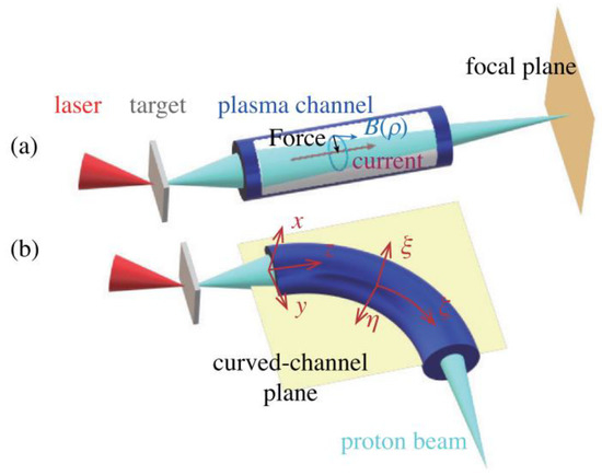
Figure 7.
Schematic concept of a proton beam focusing on propagating in a straight (a) and a curved (b) APL.
This study confirms that the APL has a one order of magnitude higher magnetic field gradient, a shorter scale focal length, and a weaker energy dependence, compared with solenoids and quadrupoles. The hundred-of-ns discharge is suitable for laser-accelerated proton beams with an ultra-short pulse duration. The APL has the ability to tightly focus the protons to a micrometer transverse size spot with good tunability. It can also be used as a windowless vacuum sealing device with heat and radiation damage resistance, simplifying the structure of the irradiation platform [54]. By combining the plasma acceleration with the APL, we can not only complete the miniaturization of the laser–plasma accelerator, but also improve the efficiency of the beam transmission and utilization. Such a compact tabletop laser accelerator can have a significant impact on various areas, such as accelerator physics [55], inertial fusion science [56], astrophysics [57], and proton oncology [58].
6. Application of Laser Proton Acceleration
6.1. Laser-Accelerated Proton Radiography of Biological Samples
Compared with attenuation-based X-ray radiography, proton radiography has advantages in fine density resolution and the imaging of biological samples [59,60,61,62]. We have studied contact imaging based on MeV energy laser-accelerated protons irradiating on ant samples [63]. The sample was placed 4 cm behind the target and was sandwiched between a 70 μm-thick Al foil (which was used to shield the transmitted laser, the target debris, and the low energy ions) and an RCF stack (one HD-V2 RCF and one EBT3 RCF). The energies of the protons that were detected by the active layers were 2.9 and 5.6 MeV for the HD-V2 RCF and the EBT3 RCF, respectively. Since the sample was attached to the RCF stack, the distance between the object and the detector was ~0, and the magnification of the system was ~1. The contact imaging setup was configured to reduce the blurring caused by multiple Coulomb scattering and to increase the spatial resolution.
Figure 8 shows the images of the ant that were recorded on (a) the HD-V2 RCF and (b) the EBT3 RCF, where the dark areas are irradiated by the proton spots. The small graphs that are inserted into the lower right corner are the entirety of the radiography images. Since the ants block a part of the low-energy protons, their shapes and their internal structures are imprinted by the color changing on the background of the proton beam spots. In the magnified images of the center big ant, both the external structure and the internal organs can be distinguished with a micrometer spatial resolution. Comparing Figure 8a,b, we find that the protons of different energies can clearly distinguish the different structures of the ants. For example, the antennae of the ant (marked by the solid red line in the figure) can be better distinguished on the HD-V2 RCF with the 2.9 MeV protons, while the tibia of the ant (marked by the red dashed line) is much clearer on the EBT3 RCF with the 5.6 MeV protons. It provides a feasible method that uses the laser-accelerated proton beam with a broad energy spectrum to analyze the structure of different depths inside the irradiated object by one single shot.
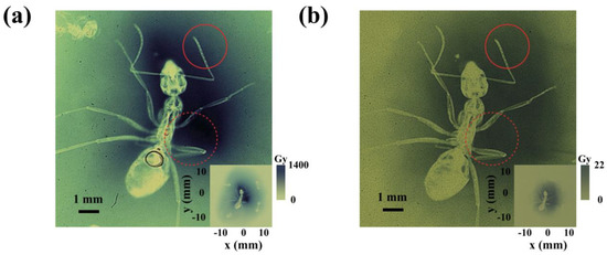
Figure 8.
Proton radiography images of an ant on the (a) HD-V2 and (b) EBT3 RCF. The small images inserted in the lower right corners of (a,b) show the complete images of the proton radiography of ants with a proton energy of 2.9 and 5.6 MeV, respectively. The part marked by the solid red line is the antennae, and the part marked by the red dashed line is the tibia.
6.2. Laser-Accelerated Ultra-High Dose Rate FLASH Radiation of Normal Cells and Tumor-Cells
The ultra-high dose rate FLASH-radiotherapy (FLASH-RT) has attracted wide attention in recent years [64]. It greatly protects normal tissues from damage, while effectively killing tumor tissues, which is suggested to be related to oxygen depletion. Due to ultra-short pulse duration, laser-accelerated protons have natural advantages in FLASH-RT, which has gradually become a hot research topic [58,65,66]. However, the detailed cell death profile and the pathways thereof are still unclear.
Normal mouse embryonic fibroblast cells were FLASH irradiated (~109 Gy/s) at a dose of ~10–40 Gy in hypoxic and normoxic conditions, with ultra-fast laser-generated particles that were generated on CLAPA [67,68]. The experiment setup is shown in Figure 9. The laser was focused onto a 100 nm plastic target using an F/2.5 OAP. The laser energy that was on target was ~1 J and the peak intensity was 5.6 × 10¹⁹ W/cm2. The ion energy spectra were measured with a Thomson parabola spectrometer (TPS) along the direction that was normal to the back surface of the target. The cells irradiation system was plugged in after the ion energy spectra were measured (Figure 9A). The ion beams entered the cells’ radiation system through a vacuum window and irradiated normally upon the cells. The vacuum window was composed of an aluminum film for light-shielding and a Kapton film for vacuum sealing. The monolayer cells that were cultured on a Mylar film were mounted on a stainless steel cell-culture cylinder, which faced toward the inner space of the cylinder, as shown in Figure 9B,C. Another Mylar film was taped onto the other side of the holder in order to seal the cylinder, avoiding the contamination and dryout of the cells during irradiation. Each cell sample was irradiated by a single shot.
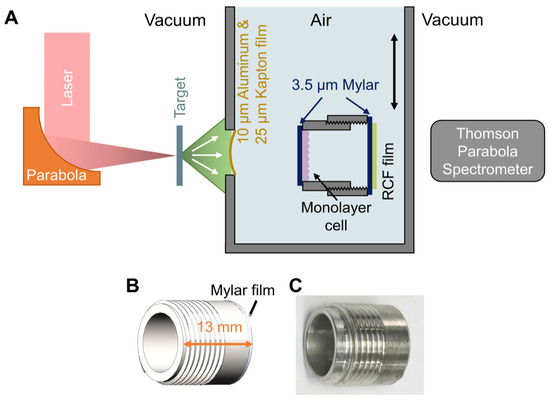
Figure 9.
Experimental setup for FLASH irradiation. (A) Schematic drawing of the experimental setup. (B,C) Side view of the cell-culture cylinder. The cells were cultured on the 3.5 µm Mylar film adhered to inner side of the cylinder.
While the cells’ irradiation system was plugged in, customized EBT3 films for dose verification were placed directly behind the sealing Mylar film. The deposited dose in the cell was calculated by the Monte-Carlo code FLUKA, with the measured energy spectra of the protons and the measured dose in the EBT3 films. The laser acceleration was completed within 1 ps. Considering the broadening of the beam duration due to the difference in the flying speed of the protons, the duration of the proton pulse that was delivered to the cell plane was ∼10 ns, corresponding to the dose rate in the order of 109 Gy/s.
We revealed early apoptosis, late apoptosis, and necrosis induced by FLASH irradiation in both cyt c+/+ and cyt c−/− mouse embryonic fibroblast cells. The apoptosis proportion of the cyt c+/+ cell was significantly lower in hypoxia than that in normoxia, indicating the increased resistance of the normal fibroblast cell after FLASH irradiation in hypoxia. The late apoptosis and necrosis proportion of the irradiated cyt c−/− was significantly lower in both hypoxia and normoxia compared to the irradiated normal cyt c+/+ cells, indicating that mitochondrial dysfunction enhanced the radio-resistance of the mouse embryonic fibroblast cells after FLASH irradiation.
We also studied the killing effect of ultra-high dose rate FLASH-IR on MCF-7 and its cancer stem cell (CSC) [67]. The ratio of apoptosis, pyroptosis, and necrosis was determined at 6, 12, and 24 h after irradiation. At the same time, we also labeled the lysosomes and detected autophagy in the cells. The results showed that the apoptosis of the irradiated CSCs was significantly lower than that of MCF-7, and the pyroptosis and the necrosis of the irradiated CSCs were also slightly lower than that of MCF-7. In addition, the response of the CSC to irradiation was slower. These results suggested the radio-resistance of the CSCs under FLASH-IR. By detecting cells’ autophagy, as well as the lysosomes, after irradiation, we found that the lysosomes and the autophagy in the CSCs were much higher (Figure 10), suggesting that CSCs may enhance their radio-resistance by increasing lysosome-mediated autophagy and decreasing apoptosis after FLASH-IR.
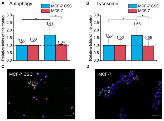
Figure 10.
Detection of autophagy and lysosomes in the irradiated MCF-7 cells and MCF-7 CSCs. (A) Compared with the control, the increase in the autophagy proportion of the irradiated group. (B) Compared with the control, the increase in lysosomes of the irradiated group. All results are expressed as means ± SD, Student’s t-test or one-way ANOVA are used for analyzing significance between the controls and the experimental groups, where p < 0.05 was marked as *. (C,D) Representative images of irradiated MCF-7 cells and MCF-7 CSCs stained with MDC autophagy detection kit and lysoTracker Red DND-99. The blue is the nucleus, the red is the lysosome, and the green is labeled autophagy.
6.3. Preparation of Graphene on SiC by Laser-Accelerated Pulsed Ion Beams
The proton beam that is driven by the ultra-intense laser has an ultra-short pulse duration of picoseconds to nanoseconds. When such a proton beam irradiates a sample, the rapid energy deposition will instantaneously heat the sample to a high temperature, which will lead to significant changes in the physical and chemical properties of the material. For example, if the irradiation distance is in the order of hundred microns, the sample temperature can reach up to eV and change to a warm, dense matter state [69,70]. When the irradiation distance is in the order of cm or mm, the temperature of the sample will also rise rapidly, until it reaches the melting point or the boiling point of the material. Therefore, it is possible to carry out material irradiation application research, such as testing the radiation resistance of materials under extreme conditions [71,72,73], or to realize the ultra-fast synthesis of some new materials [74,75].
We have carried out an application experiment using laser-accelerated ion beams to prepare graphene, utilizing the extremely high beam current [76]. Graphene that is grown on the surface of silicon carbide can be directly made into semiconductor devices, avoiding the damage that is caused by the transfer from other substrates, which leads to the decline of the electrical properties of graphene. The incident ions can break the Carbon-silicon chemical bond on the surface. In the process of high temperature annealing, silicon atoms sublimate before carbon atoms and desorb from the surface, and the enriched carbon atoms on the surface will recombine to form the graphene films. We first combined the laser-accelerated ion beam and graphene growth as demonstrated in Figure 11. After the ion irradiation, the SiC samples were annealed in a graphite enclosure at a pressure of 10−3 Pa, where the samples were heated to 1100 °C for 60 min. Finally, they were slowly cooled down to room temperature. Due to the closed environment of the graphite boat, the sublimation of the silicon atoms during the annealing process was reduced. The excess carbon atoms self-assembled into graphene on the SiC surface, as shown in Figure 11c.
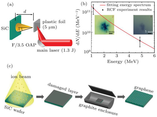
Figure 11.
(a) Schematic diagram of the experiment setup. (b) The laser-accelerated proton beam energy spectrum measured with the RCF stack detector. (c) Schematic diagram of graphene preparation after laser-accelerated ion beam irradiation and annealing.
Raman spectroscopy was used to characterize the properties of the graphene, and the results are shown in Figure 12. The D peak (~1350 cm−1) presents a disordered vibration. The characteristic G peak (~1580 cm−1) of the sp2 hybridized carbon atom is caused by the in-plane vibration of the carbon atoms. The 2D peak (~2700 cm−1) was used to characterize the stacking mode of the carbon atoms. Figure 12a shows the pristine and annealed Raman spectra of one SiC sample after it was irradiated with 10 shots at a radiation distance of 4 cm. The red and pink curves are the spectra before the irradiation and the other curves in the upper part are the spectra after irradiation. Figure 12c is the optical microscope image of the sample. As can be seen, (1) without ion irradiation, no graphene is synthesized; (2) the graphene only formed in the dark areas of Figure 12c (which corresponds to the curve of the 10-shots-D (L)); (3) in the other, brighter areas, there was no formation of graphene (which corresponds to the curve of the 10-shots-A (L)). This indicates that graphene was only synthesized after being irradiated by laser-accelerated ion beams and annealed in the subsequent process. The Raman spectra of the sample, after it was irradiated by 190 shots of the laser-accelerated ion, are shown in Figure 12b. The difference from 10-shots is that the connected D and G peaks representing the amorphous carbon peaks appeared right after the 190 shots (the blue line in Figure 12b), which indicates that there are already independent carbons on the surface of the SiC after high dose irradiation. The black and green lines correspond to the light and dark areas in Figure 12d. It can be concluded that, as the dose of irradiation increased, the area where graphene was synthesized changed from a local black spot to the entire plane.
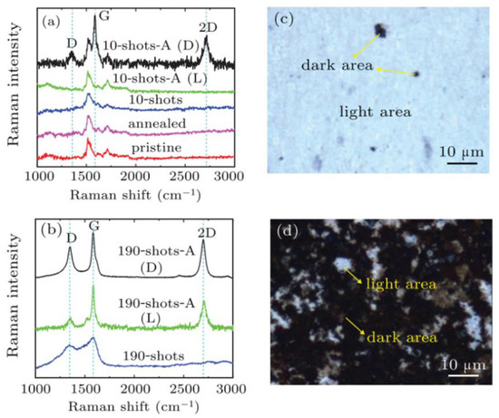
Figure 12.
(a) Raman spectra of pristine, annealed, 10-pulse irradiated (10-shots), and 10-pulse irradiated with annealed (10-shots-A) samples. (b) Raman spectra of 190 pulses irradiated (190-shots) and 190 pulses irradiated with annealed (190-shots-A) SiC samples. The D and L correspond to the dark and light areas in (c,d), respectively. Optical microscope images of samples (c) 10-shots-A and (d) 190-shots-A, respectively. Raman mapping images.
We carried out a control experiment using the continuous mono-energy protons from a traditional accelerator with the same beam fluence. We found that no graphene was generated under this condition. Although the laser-accelerated ion beams maintained a small radiation dose, the thermal effect that was caused by the continuous small interval bombardment of the instantaneous pulse beam caused more serious damage to the sample surface than the traditional ion accelerator. Apart from this, in consideration of the thermal effect that was caused by the large instantaneous beam current, the self-annealing had a certain effect on the graphene under a closer irradiation distance, as demonstrated in Figure 13a. We shortened the irradiation distance to 1 cm. Figure 13b is the Raman spectrum of the sample that was measured after it was irradiated by 100-shots. Graphene of a high quality was synthesized without annealing, and the very small D peak showed the high quality of that graphene dot.
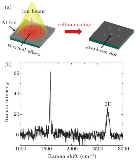
Figure 13.
(a) Schematic diagram of self-annealing graphene prepared by the thermal effect of laser-accelerated ion beam irradiation at a closer irradiation distance (d ≤ 1 cm). (b) Raman spectrum of 1 cm-100-shot SiC sample with self-annealing (baseline drift corrected).
6.4. Laser-Accelerated Ion-Beam Trace Probe (LITP) for Measuring the Electromagnetic Fields in a Magnetic Confinement Fusion Device
When an ion enters into a magnetic confinement fusion device, for example, a tokamak, its orbit will be changed by the electromagnetic field. Based on that, a new method was proposed to diagnose the profiles of both the poloidal magnetic field (Bρ) and the radial electric field (Er), which consists of a laser ion beam (LIB) and a detector with high temporal and spatial resolution, and was named as Laser-accelerated Ion-beam Trace Probe (LITP) [77]. The principle of the LITP is shown in Figure 14. The broad energy spread and the large divergence of the LIB makes its traces almost cover the whole core plasma area, which gives the LITP more capabilities, such as obtaining the 2D Bp profile or the 1D profile of both the poloidal and the radial magnetic fields at the same time [77,78], as well as the 2D electron density profile [79]. Furthermore, the LITP can be used in superconductive tokamaks, such as EAST, KSTAR, ITER, etc., because only a small window is needed to inject a laser pulse. By improving the nonlinear reconstruction method, the LITP could be applied not only in tokamak devices, but also in other toroidal devices, such as the spherical tokamak [80], reversal field pinch (RFP), etc.
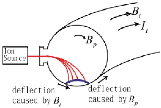
Figure 14.
A diagram to show the concept of LITP. The traces of ions with different energy are shown as the red lines, and the blue line shows the ion positions on the detector.
As a new diagnostic method of the core electromagnetic field, the LITP is expected to realize the first application of the advanced laser accelerator in magnetic confinement fusion. We have designed and verified the feasibility of the LITP ion detection through systemic experiments [81]. A CsI(Tl) scintillator that was coupled with an imaging system that was composed of an optical lens and an optical fiber array for LITP was designed and tested on the HL-2A tokamak device in the Southwestern Institute of Physics. The scintillator detector was set at 100 mm to the edge of the plasma and the temperature at its location was about 110 °C–340 °C. The detector was sent into the plasma region using a long-range stepper motor translation linear stage. The signal light from the scintillator was transported by a well-shielded image system and recorded with an ultrafast CCD. The CsI scintillator was not damaged by the harsh environment after being placed in the tokamak for three days, and the real background noise that was caused by the hot plasma electrons and the radiation was measured. We found that the background noise was completely suppressed when using an ultrafast camera and a microsecond shutter. The black curve in Figure 15, which is the intensity of the background signal caused by soft X-rays in the HL-2A tokamak, decreases rapidly (from 1000 to 10) as the shutter time decreases (from 10 ms to 0.1 ms). The corresponding CCD images at the exposure times of A (10 ms), B (1 ms), and C (0.1 ms) are illustrated below. When the exposure time was shorter than 0.2 ms, the background signal was reduced to the same level as the dark noise of the CCD.
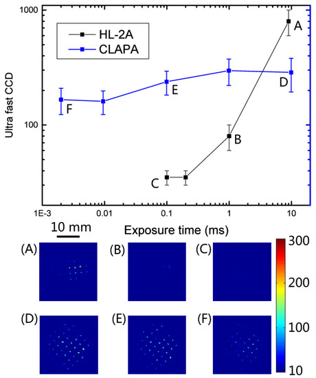
Figure 15.
The black points are the intensity of the background signal in the HL-2A tokamak versus the exposure time, the corresponding CCD images at the exposure times of (A) 10 ms, (B) 1 ms, and (C) 0:1 ms. The background signal is mainly soft X-ray in the tokamak device that was caused by the bremsstrahlung of electrons. When the exposure time is shorter than 0.2 ms, the background signal is reduced to the same level as the dark noise of the CCD. The blue points are the result of the proton signal intensity detected by the ultrafast CCD with different exposure times of (D) 9 ms, (E) 99 µs, and (F) 2 µs on CLAPA. At the exposure time of 1 ms, the proton signal intensity is already more than one order of magnitude of the background intensity.
The change in the proton beam signal with the CCD shutter time was also detected on CLAPA. The 45 TW laser-accelerated protons with a central energy of 1 MeV were collected by the magnet triplet and transported onto the CsI scintillator. The signal that was detected by the ultrafast CCD with different exposure times of D (9.9 ms), E (99 μs), and F (2 μs) is shown as the blue line in Figure 15. With the shortening of the exposure time, there was no significant change in the signal intensity on the scintillator for the laser-accelerated protons. At the exposure time of 1 ms, the proton signal intensity was already more than one order of magnitude of the background intensity in HL-2a. Based on the result above, only the dark noise of the detection instrument needs to be considered in the LITP experiment. These calibrations and tests verified the feasibility of the LITP.
7. Summary
Due to the ultra-high acceleration gradient, laser-driven proton acceleration has attracted the attention of scientists in many fields. This paper has introduced the recent progress of laser proton acceleration and its application at Peking University, mainly in the last five years. The compact laser plasma accelerator (CLAPA) was established in 2018, and it can stably produce and transport proton beams with energies of less than 10 MeV, an energy spread of less than 1%, and several to tens of pC charge. The CLAPA beamline is an object-image point analyzing system that ensures the transmission efficiency and the energy selection accuracy for proton beams with a large initial divergence angle and energy spread. Based on CLAPA, we have developed a variety of beam regulation methods and have systematically measured the emittance of laser-accelerated proton beams for the first time. A spread-out Bragg peak (SOBP) has been produced with high-precision beam control, which is essential for cancer therapy. Some application experiments that are based on laser-accelerated proton beams have also been carried out, such as proton radiographs, ion-beam trace probes for plasma diagnosis, the preparation of graphene on SiC, ultra-high dose FLASH radiation of cancer cells, and so on. The above applications utilize the unique characteristics of laser-accelerated protons, even though some of the characteristics are considered to be shortcomings (e.g., wide energy spread). It indicates that it is important to find suitable application fields and methods for this new accelerator and beam. CLAPA II, which is a 100 MeV proton beam accelerator that is based on a 2-PW laser, as well as a prototype of tumor radiotherapy, is under construction. CLAPA II will greatly improve the performance of laser accelerators and may promote the real-world application of laser accelerators, especially in malignant tumor radiotherapy.
This work was supported by the Natural Science Foundation of China (Grants No. 11975037, 12122501, and 11921006), National Grand Instrument Project (No. 2019YFF01014400, No. 2019YFF01014404, No. 2019YFF01014403 and No. 2019YFF01014402), Beijing outstanding young scientists project, and ITER-CHINA program (grant 2015GB120001).
The simulations were supported by the High-performance Computing Platform of Peking University.
Author Contributions
Conceptualization, C.L. (Chen Lin), X.Y., W.M., K.Z., C.X. and G.Y.; Methodology, formal analysis, investigation, visualization, data curation, D.L., T.Y. and M.W. contributed to the CLAPA proton acceleration and beamline experiments; K.W. contributed to the CLAPAII beamline design; Z.M., C.L. (Chunyang Lu) and G.Y. contributed to the FLASH irradiation; M.W. contributed to the LITP application; D.L. contributed to ion irradiation experiment; Investigation, Resources, Y.Z., Y.G. and J.C. contributed to the laser system; writing—original draft preparation, D.L., T.Y., M.W., K.W. and Z.M.; writing—review and editing, C.L. (Chen Lin); Supervision, C.L. (Chen Lin), X.Y., W.M., K.Z., T.T. and J.C.; project administration, X.Y. and C.L. (Chen Lin); Funding acquisition, X.Y., C.L. (Chen Lin), W.M. and K.Z. All authors have read and agreed to the published version of the manuscript.
Funding
This work was supported by the Natural Science Foundation of China (Grants No. 11975037, 12122501, and 11921006), National Grand Instrument Project (No. 2019YFF01014400, No. 2019YFF01014404, No. 2019YFF01014403 and No. 2019YFF01014402), Beijing outstanding young scientists project, and ITER-CHINA program (grant 2015GB120001).
Institutional Review Board Statement
Not applicable.
Informed Consent Statement
Not applicable.
Data Availability Statement
The data that support the findings of this study are available from the corresponding author upon reasonable request.
Conflicts of Interest
The authors declare no conflict of interest.
References
- Tajima, T.; Dawson, J.M. Laser electron accelerator. Phys. Rev. Lett. 1979, 43, 267. [Google Scholar] [CrossRef]
- Danson, C.; Haefner, C.; Bromage, J.; Butcher, T.; Chanteloup, J.-C.; Chowdhury, E.; Galvanauskas, A.; Gizzi, L.; Hein, J.; Hillier, D.; et al. Petawatt and exawatt class lasers worldwide. High Power Laser Sci. Eng. 2019, 7, e54. [Google Scholar] [CrossRef]
- Mourou, G. Nobel lecture: Extreme light physics and application. Rev. Mod. Phys. 2019, 91, 030501. [Google Scholar] [CrossRef]
- Esarey, E.; Schroeder, C.B.; Leemans, W.P. Physics of laser-driven plasma-based electron accelerators. Rev. Mod. Phys. 2009, 81, 1229. [Google Scholar] [CrossRef]
- Macchi, A.; Borghesi, M.; Passoni, M. Ion acceleration by superintense laser-plasma interaction. Rev. Mod. Phys. 2013, 85, 751–793. [Google Scholar] [CrossRef]
- Gonsalves, A.J.; Nakamura, K.; Daniels, J.; Benedetti, C.; Pieronek, C.; de Raadt, T.C.H.; Steinke, S.; Bin, J.H.; Bulanov, S.S.; van Tilborg, J.; et al. Petawatt laser guiding and electron beam acceleration to 8 GeV in a laser-heated capillary discharge waveguide. Phys. Rev. Lett. 2019, 122, 084801. [Google Scholar] [CrossRef]
- Higginson, A.; Gray, R.J.; King, M.; Dance, R.J.; Williamson, S.D.; Butler, N.M.; Wilson, R.; Capdessus, R.; Armstrong, C.; Green, J.S.; et al. Near-100 MeV protons via a laser-driven transparency-enhanced hybrid acceleration scheme. Nat. Commun. 2018, 9, 724. [Google Scholar] [CrossRef] [PubMed]
- Daido, H.; Nishiuchi, M.; Pirozhkov, A.S. Review of laser-driven ion sources and their applications. Rep. Prog. Phys. 2012, 75, 056401. [Google Scholar] [CrossRef]
- Raffestin, D.; Lecherbourg, L.; Lantuéjoul, I.; Vauzour, B.; Masson-Laborde, P.E.; Davoine, X.; Blanchot, N.; Dubois, J.L.; Vaisseau, X.; d’Humières, E.; et al. Enhanced ion acceleration using the high-energy petawatt PETAL laser. Matter Radiat. Extrem. 2021, 6, 056901. [Google Scholar] [CrossRef]
- Okamura, M. Laser ion source for heavy ion inertial fusion. Matter Radiat. Extrem. 2018, 3, 61. [Google Scholar] [CrossRef]
- Martinez, B.; Chen, S.N.; Bolaños, S.; Blanchot, N.; Boutoux, G.; Cayzac, W.; Courtois, C.; Davoine, X.; Duval, A.; Horny, V.; et al. Numerical investigation of spallation neutrons generated from petawatt-scale laser-driven proton beams. Matter Radiat. Extrem. 2022, 7, 024401. [Google Scholar] [CrossRef]
- Romano, F.; Schillaci, F.; Cirrone, G.A.P.; Cuttone, G.; Scuderi, V.; Allegra, L.; Amato, A.; Amico, A.; Candiano, G.; De Luca, G.; et al. The ELIMED transport and dosimetry beamline for laser-driven ion beams. Nucl. Instrum. Methods Phys. Res. Sect. A 2016, 829, 153. [Google Scholar] [CrossRef]
- Masood, U.; Bussmann, M.; Cowan, T.E.; Enghardt, W.; Karsch, L.; Kroll, F. A compact solution for ion beam therapy with laser accelerated protons. Appl. Phys. B 2014, 117, 41. [Google Scholar] [CrossRef]
- Pommarel, L.; Vauzour, B.; Mégnin-Chanet, F.; Bayart, E.; Delmas, O.; Goudjil, F.; Nauraye, C.; Letellier, V.; Pouzoulet, F.; Schillaci, F.; et al. Spectral and spatial shaping of a laser-produced ion beam for radiation-biology experiments. Phys. Rev. Accel. Beams 2017, 20, 032801. [Google Scholar] [CrossRef]
- Mora, P. Plasma expansion into a vacuum. Phys. Rev. Lett. 2003, 90, 185002. [Google Scholar] [CrossRef] [PubMed]
- Pukhov, A. Three-dimensional simulations of ion acceleration from a foil irradiated by a short-pulse laser. Phys. Rev. Lett. 2001, 86, 3562. [Google Scholar] [CrossRef] [PubMed]
- Palmer, C.A.J.; Schreiber, J.; Nagel, S.R.; Dover, N.P.; Bellei, C.; Beg, F.N.; Bott, S.; Clarke, R.J.; Dangor, A.E.; Hassan, S.M.; et al. Rayleigh–Taylor instability of an ultrathin foil accelerated by the radiation pressure of an intense laser. Phys. Rev. Lett. 2012, 108, 225002. [Google Scholar] [CrossRef]
- Wan, Y.; Andriyash, I.A.; Lu, W.; Mori, W.B.; Malka, V. Effects of the transverse instability and wave breaking on the laser-driven thin foil acceleration. Phys. Rev. Lett. 2020, 125, 104801. [Google Scholar] [CrossRef]
- Zhu, J.G.; Wu, M.J.; Liao, Q.; Geng, Y.X.; Zhu, K.; Li, C.C.; Xu, X.H.; Li, D.Y.; Shou, Y.R.; Yang, T.; et al. Experimental demonstration of a laser proton accelerator with accurate beam control through image-relaying transport. Phys. Rev. Accel. Beams 2019, 22, 061302. [Google Scholar] [CrossRef]
- Geng, Y.X.; Liao, Q.; Shou, Y.R.; Zhu, J.G.; Xu, X.H.; Wu, M.J.; Wang, P.J.; Li, D.Y.; Yang, T.; Hu, R.H.; et al. Generating proton beams exceeding 10 MeV using high contrast 60 TW laser. Chin. Phys. Lett. 2018, 35, 092901. [Google Scholar] [CrossRef]
- Geng, Y.X.; Wu, D.; Yu, W.; Sheng, Z.M.; Fritzsche, S.; Liao, Q.; Wu, M.J.; Xu, X.H.; Li, D.Y.; Ma, W.J.; et al. Proton beams from intense laser-solid interaction: Effects of the target materials. Matter Radiat. Extrem. 2020, 5, 064402. [Google Scholar] [CrossRef]
- Zhu, J.G.; Zhu, K.; Tao, L.; Geng, Y.X.; Lin, C.; Ma, W.J.; Lu, H.Y.; Zhao, Y.Y.; Lu, Y.R.; Chen, J.E.; et al. Beam line design of compact laser plasma accelerator. Chin. Phys. Lett. 2017, 34, 054101. [Google Scholar] [CrossRef]
- Zhu, J.G.; Zhu, K.; Tao, L.; Xu, X.H.; Lin, C.; Ma, W.J.; Lu, H.Y.; Zhao, Y.Y.; Lu, Y.R.; Chen, J.E.; et al. Distribution uniformity of laser-accelerated proton beams. Chin. Phys. C 2017, 41, 097001. [Google Scholar] [CrossRef]
- Wilks, S.C.; Langdon, A.B.; Cowan, T.E.; Roth, M.; Singh, M.; Hatchett, S.; Key, M.H.; Pennington, D.; MacKinnon, A.; Snavely, R.A. Energetic proton generation in ultra-intense laser–solid interactions. Phys. Plasmas 2001, 8, 542–549. [Google Scholar] [CrossRef]
- Xu, X.H.; Liao, Q.; Wu, M.J.; Geng, Y.X.; Li, D.Y.; Zhu, J.G.; Li, C.C.; Hu, R.H.; Shou, Y.R.; Chen, Y.H.; et al. Detection and analysis of laser driven proton beams by calibrated Gafchromic HD-V2 and MD-V3 radiochromic films. Rev. Sci. Instrum. 2019, 90, 033306. [Google Scholar] [CrossRef] [PubMed]
- Wu, M.; Zhu, J.; Li, D.; Yang, T.; Liao, Q.; Geng, Y.; Xu, X.; Li, C.; Shou, Y.; Zhao, Y.; et al. Collection and focusing of laser accelerated proton beam by an electromagnetic quadrupole triplet lens. Nucl. Instrum. Methods Phys. Res. Sect. A 2020, 955, 163249. [Google Scholar] [CrossRef]
- Yan, X.Q.; Lin, C.; Sheng, Z.M.; Guo, Z.Y.; Liu, B.C.; Lu, Y.R.; Fang, J.X.; Chen, J.E. Generating high-current monoenergetic proton beams by a circularly polarized laser pulse in the phase-stable acceleration regime. Phys. Rev. Lett. 2008, 100, 135003. [Google Scholar] [CrossRef]
- Esirkepov, T.; Borghesi, M.; Bulanov, S.V.; Mourou, G.; Tajima, T. Highly efficient relativistic-ion generation in the laser-piston regime. Phys. Rev. Lett. 2004, 92, 175003. [Google Scholar] [CrossRef]
- Kar, S.; Ahmed, H.; Prasad, R.; Cerchez, M.; Brauckmann, S.; Aurand, B.; Cantono, G.; Hadjisolomou, P.; Lewis, C.L.S.; Macchi, A.; et al. Guided post-acceleration of laser-driven ions by a miniature modular structure. Nat. Commun. 2016, 7, 10792. [Google Scholar] [CrossRef]
- Bardon, M.; Moreau, J.G.; Romagnani, L.; Rousseaux, C.; Ferri, M.; Lefévre, F.; Lantuéjoul, I.; Etchessahar, B.; Bazzoli, S.; Farcage, D.; et al. Physics of chromatic focusing, post-acceleration and bunching of laser-driven proton beams in helical coil targets. Plasma Phys. Control. Fusion 2020, 62, 125019. [Google Scholar] [CrossRef]
- Floettmann, K. Some basic features of the beam emittance. Phys. Rev. ST Accel. Beams 2003, 6, 034202. [Google Scholar] [CrossRef]
- Cowan, T.E.; Fuchs, J.; Ruhl, H.; Kemp, A.; Audebert, P.; Roth, M.; Stephens, R.; Barton, I.; Blazevic, A.; Brambrink, E.; et al. Ultralow emittance, multi-MeV proton beams from a laser virtual-cathode plasma accelerator. Phys. Rev. Lett. 2004, 92, 204801. [Google Scholar] [CrossRef] [PubMed]
- Wu, M.J.; Li, D.Y.; Zhu, J.G.; Yang, T.; Hu, X.Y.; Geng, Y.X.; Zhu, K.; Easton, M.J.; Zhao, Y.Y.; Zhang, A.L.; et al. Emittance measurement along transport beam line for laser driven protons. Phys. Rev. Accel. Beams 2020, 23, 031302. [Google Scholar] [CrossRef]
- Zhu, J.G.; Wu, M.J.; Zhu, K.; Geng, Y.X.; Liao, Q.; Li, D.Y.; Yang, T.; Eatson, M.J.; Li, C.C.; Xu, X.H.; et al. Demonstration of tailored energy deposition in a laser proton accelerator. Phys. Rev. Accel. Beams 2020, 23, 121304. [Google Scholar] [CrossRef]
- Tajima, T.; Habs, D.; Yan, X. Laser Acceleration of Ions for Radiation Therapy; World Scientific: Singapore, 2009; pp. 201–228. [Google Scholar]
- Yan, X.Q.; Tajima, T.; Hegelich, M.; Yin, L.; Habs, D. Theory of laser ion acceleration from a foil target of nanometer thickness. Appl. Phys. B 2009, 98, 711–721. [Google Scholar] [CrossRef]
- Wang, H.Y.; Yan, X.Q.; Chen, J.E.; He, X.T.; Ma, W.J.; Bin, J.H.; Schreiber, J.; Tajima, T.; Habs, D. Efficient and stable acceleration by irradiating a two-layer target with a linearly polarized laser pulse. Phys. Plasmas 2013, 20, 013101. [Google Scholar] [CrossRef]
- Esirkepov, T.; Bulanov, S.V.; Nishihara, K.; Tajima, T.; Pegoraro, F.; Khoroshkov, V.S.; Mima, K.; Daido, H.; Kato, Y.; Kitagawa, Y.; et al. Proposed double-layer target for the generation of high-quality laser-accelerated ion beams. Phys. Rev. Lett. 2002, 89, 175003. [Google Scholar] [CrossRef]
- Necas, A.; Tajima, T.; Mourou, G.; Osvay, K. Laser ion acceleration in a near critical density trap. Photonics 2022, 9, 453. [Google Scholar] [CrossRef]
- Ma, W.J.; Kim, I.J.; Yu, J.Q.; Choi, I.W.; Singh, P.K.; Lee, H.W.; Sung, J.H.; Lee, S.K.; Lin, C.; Liao, Q.; et al. Laser Acceleration of highly energetic carbon ions using a double-layer target composed of slightly underdense plasma and ultrathin foil. Phys. Rev. Lett. 2019, 122, 014803. [Google Scholar] [CrossRef] [PubMed]
- Esirkepov, T.; Yamagiwa, M.; Tajima, T. Laser ion-acceleration scaling laws seen in multiparametric particle-in-cell simulations. Phys. Rev. Lett. 2006, 96, 105001. [Google Scholar] [CrossRef]
- Henig, A.; Steinke, S.; Schnürer, M.; Sokollik, T.; Hörlein, R.; Kiefer, D.; Jung, D.; Schreiber, J.; Hegelich, B.M.; Yan, X.Q.; et al. Radiation-pressure acceleration of ion beams driven by circularly polarized laser pulses. Phys. Rev. Lett. 2009, 103, 245003. [Google Scholar] [CrossRef]
- Kar, S.; Kakolee, K.F.; Qiao, B.; Macchi, A.; Cerchez, M.; Doria, D.; Geissler, M.; McKenna, P.; Neely, D.; Osterholz, J.; et al. Ion acceleration in multispecies targets driven by intense laser radiation pressure. Phys. Rev. Lett. 2012, 109, 185006. [Google Scholar] [CrossRef]
- Kim, I.J.; Pae, K.H.; Choi, I.W.; Lee, C.L.; Kim, H.T.; Singhal, H.; Sung, J.H.; Lee, S.K.; Lee, H.W.; Nickles, P.V.; et al. Radiation pressure acceleration of protons to 93 MeV with circularly polarized petawatt laser pulses. Phys. Plasmas 2016, 23, 070701. [Google Scholar] [CrossRef]
- Fuchs, J.; Antici, P.; d’Humières, E.; Lefebvre, E.; Borghesi, M.; Brambrink, E.; Cecchetti, C.A.; Kaluza, M.; Malka, V.; Manclossi, M.; et al. Laser-driven proton scaling laws and new paths towards energy increase. Nat. Phys. 2008, 2, 28. [Google Scholar] [CrossRef]
- Wang, K.D.; Zhu, K.; Easton, M.J.; Li, Y.J.; Lin, C.; Yan, X.Q. Achromatic beamline design for a laser-driven proton therapy accelerator. Phys. Rev. Accel. Beams 2020, 23, 111302. [Google Scholar] [CrossRef]
- Brouwer, L.; Caspi, S.; Edwards, K.; Godeke, A.; Prestemon, S. Design and test of a curved superconducting dipole magnet for proton therapy. Nucl. Instrum. Methods Phys. Res. Sect. A 2020, 957, 163414. [Google Scholar] [CrossRef]
- Leemans, W.P.; Nagler, B.; Gonsalves, A.J.; Toth, C.; Nakamura, K.; Geddes, C.G.R.; Esarey, E.; Schroeder, C.B.; Hooker, S.M. GeV electron beams from a centimetre-scale accelerator. Nat. Phys. 2006, 2, 696–699. [Google Scholar] [CrossRef]
- Steinke, S.; van Tilborg, J.; Benedetti, C.; Geddes, C.G.R.; Schroeder, C.B.; Daniels, J.; Swanson, K.K.; Gonsalves, A.J.; Nakamura, K.; Matlis, N.H.; et al. Multistage coupling of independent laser-plasma accelerators. Nature 2016, 530, 190. [Google Scholar] [CrossRef]
- Van Tilborg, J.; Steinke, S.; Geddes, C.G.R.; Matlis, N.H.; Shaw, B.H.; Gonsalves, A.J.; Huijts, J.V.; Nakamura, K.; Daniels, J.; Schroeder, C.B.; et al. Active plasma lensing for relativistic laser-plasma-accelerated electron beams. Phys. Rev. Lett. 2015, 115, 184802. [Google Scholar] [CrossRef]
- Pompili, R.; Anania, M.P.; Bellaveglia, M.; Biagioni, A.; Bini, S.; Bisesto, F.; Brentegani, E.; Castorina, G.; Chiadroni, E.; Cianchi, A.; et al. Experimental characterization of active plasma lensing for electron beams. Appl. Phys. Lett. 2017, 110, 104101. [Google Scholar] [CrossRef]
- Lindstrøm, C.A.; Adli, E.; Boyle, G.; Corsini, R.; Dyson, A.E.; Farabolini, W.; Hooker, S.M.; Meisel, M.; Osterhoff, J.; Röckemann, J.-H.; et al. Emittance preservation in an aberration-free active plasma lens. Phys. Rev. Lett. 2018, 121, 194801. [Google Scholar] [CrossRef] [PubMed]
- Yang, T.; Cheng, H.; Yan, Y.; Wu, M.; Li, D.; Li, Y.; Xia, Y.; Lin, C.; Yan, X. Designing of active plasma lens for focusing laser-plasma-accelerated pulsed proton beams. Phys. Rev. Accel. Beams 2021, 24, 031301. [Google Scholar] [CrossRef]
- Hershcovitch, A. High-pressure arcs as vacuum-atmosphere interface and plasma lens for nonvacuum electron beam welding machines, electron beam melting, and nonvacuum ion material modification. J. Appl. Phys. 1995, 78, 5283. [Google Scholar] [CrossRef]
- Lu, L.; Ma, W.; Li, C.; He, T.; Yang, L.; Sun, L.; Xu, X.; Wang, W.; Shi, L. New developments of HIF injector. Matter Radiat. Extrem. 2018, 3, 50. [Google Scholar] [CrossRef]
- Hofmann, I. Review of accelerator driven heavy ion nuclear fusion. Matter Radiat. Extrem. 2018, 3, 1. [Google Scholar] [CrossRef]
- Yao, W.; Fazzini, A.; Chen, S.N.; Burdonov, K.; Antici, P.; Béard, J.; Bolaños, S.; Ciardi, A.; Diab, R.; Filippov, E.D.; et al. Detailed characterization of a laboratory magnetized supercritical collisionless shock and of the associated proton energization. Matter Radiat. Extrem. 2022, 7, 014402. [Google Scholar] [CrossRef]
- Kroll, F.; Brack, F.; Bernert, C.; Bock, S.; Bodenstein, E.; Brüchner, K.; Cowan, T.E.; Gaus, L.; Gebhardt, R.; Helbig, U.; et al. Tumour irradiation in mice with a laser-accelerated proton beam. Nat. Phys. 2022, 18, 316. [Google Scholar] [CrossRef]
- Scott, W.T. The theory of small-angle multiple scattering of fast charged particles. Rev. Mod. Phys. 1963, 35, 231. [Google Scholar] [CrossRef]
- Faenov, A.Y.; Pikuz, T.A.; Fukuda, Y.; Kando, M.; Kotaki, H.; Homma, T.; Kawase, K.; Kameshima, T.; Pirozhkov, A.; Yogo, A.; et al. Submicron iconography of nanostructures using a femtosecond-laser-driven-cluster-based source. Appl. Phys. Lett. 2009, 95, 101107. [Google Scholar] [CrossRef]
- Son, J.; Lee, C.H.; Kang, J.; Jang, D.Y.; Park, J.; Kim, Y.H.; Kim, Y.K.; Choi, C.I.; Kim, I.J.; Choi, I.W.; et al. Fine phantom image from laser-induced proton radiography with a spatial resolution of several μm. J. Korean Phys. Soc. 2014, 65, 6. [Google Scholar] [CrossRef]
- Wang, W.; Shen, B.; Zhang, H.; Lu, X.; Wang, C.; Liu, Y.; Yu, L.; Chu, Y.; Li, Y.; Xu, T.; et al. Large-scale proton radiography with micrometer spatial resolution using femtosecond petawatt laser system. AIP Adv. 2015, 5, 107214. [Google Scholar]
- Li, D.Y.; Xu, X.H.; Yang, T.; Wu, M.J.; Zhang, Y.F.; Cheng, H.; Hu, X.Y.; Geng, Y.X.; Zhu, J.G.; Zhao, Y.Y.; et al. Influence factors of resolution in laser accelerated proton radiography and image deblurring. AIP Adv. 2021, 11, 085316. [Google Scholar] [CrossRef]
- Bourhis, J.; Sozzi, W.J.; Jorge, P.G.; Gaide, O.; Bailat, C.; Duclos, F.; Patin, D.; Ozsahin, M.; Bochud, F.; Germond, J.; et al. Treatment of a first patient with FLASH-radiotherapy. Radiother. Oncol. 2019, 139, 18–22. [Google Scholar] [CrossRef] [PubMed]
- Bin, J.; Obst-Huebl, L.; Mao, J.; Nakamura, K.; Geulig, L.D.; Chang, H.; Ji, Q.; He, L.; Chant, J.D.; Kober, Z.; et al. A new platform for ultra-high dose rate radiobiological research using the BELLA PW laser proton beamline. Sci. Rep. 2022, 12, 1484. [Google Scholar] [CrossRef] [PubMed]
- Bayart, E.; Flacco, A.; Delmas, O.; Pommarel, L.; Levy, D.; Cavallone, M.; Megnin-Chanet, F.; Deutsch, E.; Malka, V. Fast dose fractionation using ultra-short laser accelerated proton pulses can increase cancer cell mortality, which relies on functional PARP1 protein. Sci. Rep. 2019, 9, 10132. [Google Scholar] [CrossRef]
- Yang, G.; Lu, C.; Mei, Z.; Sun, X.; Han, J.; Qian, J.; Liang, Y.; Pan, Z.; Kong, D.; Xu, S.; et al. Association of cancer stem cell radio-resistance under ultra-high dose rate FLASH irradiation with lysosome-mediated autophagy. Front. Cell Dev. Biol. 2021, 9, 1032. [Google Scholar] [CrossRef]
- Han, J.; Mei, Z.; Lu, C.; Qian, J.; Liang, Y.; Sun, X.; Pan, Z.; Kong, D.; Xu, S.; Liu, Z.; et al. Ultra-high dose rate FLASH irradiation induced radio-resistance of normal fibroblast cells can be enhanced by hypoxia and mitochondrial dysfunction resulting from loss of cytochrome C. Front. Cell Dev. Biol. 2021, 9, 1089. [Google Scholar] [CrossRef]
- Patel, P.K.; Mackinnon, A.J.; Key, M.H.; Cowan, T.E.; Foord, M.E.; Allen, M.; Price, D.F.; Ruhl, H.; Springer, P.T.; Stephens, R. Isochoric heating of solid-density matter with an ultrafast proton beam. Phys. Rev. Lett. 2003, 91, 125004. [Google Scholar] [CrossRef]
- Dyer, G.M.; Bernstein, A.C.; Cho, B.I.; Osterholz, J.; Grigsby, W.; Dalton, A.; Shepherd, R.; Ping, Y.; Chen, H.; Widmann, K.; et al. Equation-of-state measurement of dense plasmas heated with fast protons. Phys. Rev. Lett. 2008, 101, 015002. [Google Scholar] [CrossRef]
- Barberio, M.; Scisciò, M.; Vallières, S.; Cardelli, F.; Chen, S.N.; Famulari, G.; Gangolf, T.; Revet, G.; Schiavi, A.; Senzacqua, M.; et al. Laser-accelerated particle beams for stress testing of materials. Nat. Commun. 2018, 9, 372. [Google Scholar] [CrossRef]
- Alvarez, J.; Mima, K.; Tanaka, K.A.; Fernandez, J.; Garoz, D.; Habara, H.; Kikuyama, K.; Kondo, K.; Perlado, J.M. Ultraintense lasers as a promising research tool for fusion material testing: Production of ions, X-rays and neutrons. Plasma Fusion Res. 2013, 8, 3404055. [Google Scholar] [CrossRef]
- Barberio, M.; Vallières, S.; Scisciò, M.; Kolhatkar, G.; Ruediger, A.; Antici, P. Graphitization of diamond by laser-accelerated proton beams. Carbon 2018, 139, 531. [Google Scholar] [CrossRef]
- Barberio, M.; Scisciò, M.; Vallières, S.; Veltri, S.; Morabito, A.; Antici, P. Laser-generated proton beams for high-precision ultra-fast crystal synthesis. Sci. Rep. 2017, 7, 12522. [Google Scholar] [CrossRef]
- Barberio, M.; Giusepponi, S.; Vallières, S.; Scisció, M.; Celino, M.; Antici, P. Ultra-fast high-precision metallic nanoparticle synthesis using laser-accelerated protons. Sci. Rep. 2020, 10, 9570. [Google Scholar] [CrossRef]
- Zhou, D.; Li, D.; Chen, Y.; Wu, M.; Yang, T.; Cheng, H.; Li, Y.; Chen, Y.; Li, Y.; Geng, Y.; et al. Preparation of graphene on SiC by laser-accelerated pulsed ion beams. Chin. Phys. B 2021, 30, 116106. [Google Scholar] [CrossRef]
- Yang, X.Y.; Chen, Y.H.; Lin, C.; Wang, L.; Xu, M.; Wang, X.G.; Xiao, C.J. A new method of measuring the poloidal magnetic and radial electric fields in a tokamak using a laser-accelerated ion-beam trace probe. Rev. Sci. Instrum. 2014, 85, 11E429. [Google Scholar] [CrossRef] [PubMed]
- Yang, X.; Xiao, C.; Chen, Y.; Xu, T.; Lin, C.; Wang, L.; Xu, M.; Yu, Y. 2D profile of poloidal magnetic field diagnosed by a laser-driven ion-beam trace probe (LITP). Rev. Sci. Instrum. 2016, 87, 11D608. [Google Scholar] [CrossRef] [PubMed]
- Chen, Y.H.; Yang, X.Y.; Lin, C.; Wang, L.; Xu, M.; Wang, X.G.; Xiao, C.J. 2D electron density profile measurement in tokamak by laser-accelerated ion-beam probe. Rev. Sci. Instrum. 2014, 85, 11D860. [Google Scholar] [CrossRef]
- Yang, X.; Xiao, C.; Chen, Y.; Xu, T.; Yu, Y.; Xu, M.; Wang, L.; Wang, X.; Lin, C. Theoretical study on the laser-driven ion-beam trace probe in toroidal devices with large poloidal magnetic field. JINST 2018, 13, C03034. [Google Scholar] [CrossRef]
- Wu, M.J.; Yang, X.Y.; Xu, T.C.; Li, D.Y.; Chen, Y.H.; Zhu, J.G.; Yang, T.; Hu, X.Y.; Ma, W.J.; Zhao, Y.Y.; et al. Calibration and test of CsI scintillator ion detection system for tokamak magnetic field diagnosis based on laser-driven ion-beam trace probe (LITP). Nucl. Fusion 2022, 62, 106028. [Google Scholar] [CrossRef]
Disclaimer/Publisher’s Note: The statements, opinions and data contained in all publications are solely those of the individual author(s) and contributor(s) and not of MDPI and/or the editor(s). MDPI and/or the editor(s) disclaim responsibility for any injury to people or property resulting from any ideas, methods, instructions or products referred to in the content. |
© 2023 by the authors. Licensee MDPI, Basel, Switzerland. This article is an open access article distributed under the terms and conditions of the Creative Commons Attribution (CC BY) license (https://creativecommons.org/licenses/by/4.0/).