Communication

Study on Supermode Control of External Cavity VCSEL Array with Parallel-Coupled Model

1
Institute of Atomic and Molecular Science, Shaanxi University of Science and Technology, Xi’an 710021, China
2
Institute of Advanced Technology on Semiconductor Optics & Electronics, Institute of Laser Engineering, Faculty of Materials and Manufacturing, Beijing University of Technology, Beijing 100124, China
*
Authors to whom correspondence should be addressed.
These authors contributed equally to this work.
Photonics 2023, 10(2), 115; https://doi.org/10.3390/photonics10020115
Submission received: 22 December 2022 / Revised: 13 January 2023 / Accepted: 19 January 2023 / Published: 22 January 2023
(This article belongs to the Special Issue Vertical-Cavity Surface-Emitting Lasers (VCSELs))

Abstract

:
A vertical-cavity surface-emitting laser (VCSEL) is easily made into a two-dimensional array to improve its output power. However, if the near-field complex amplitude output cannot be stabilized in the lowest supermode generated by the fundamental transverse mode, the spot cannot converge on the center normal of the far-field array geometry, and the energy will be diverged. The external cavity is prepared for the VCSEL array, and the output of the array can be stabilized in the lowest order supermode generated by the fundamental transverse mode by supermode control through diffraction coupling. In this study, the parallel-coupled model for the 2-dimensional VCSEL array based on Fresnel diffraction integration was established and used to numerically calculate and analyze the influence on the supermodes’ thresholds of different array distributions, array elements’ transverse modes and duty ratios versus the length of the external cavity. The simulation results show that the square array provides a wider range of external cavity control length ( 0.2 d 2 / λ and approximately 0.9   to   1.0 d 2 / λ ). The lowest supermode of the fundamental transverse mode can be outputted. For the regular hexagonal array with the length of the external cavity of 0.15 d 2 / λ and 0.6 d 2 / λ . The results have important reference significance for the design of an external cavity VCSEL array, which can control the supermode and obtain VCSEL coherent array beams with high power and near diffraction limits.

1. Introduction

As a low-cost, single longitudinal mode laser source, the vertical-cavity surface-emitting laser (VCSEL) has the distinct advantages of excellent beam quality, low threshold working current and high-density integration. It has been widely used in various fields, such as laser communication [1], pump source [2], detection sensors [3], and medical and healthcare [4,5]. In these application scenarios, it is of great significance to prepare a VCSEL source with a high power output and a far-field divergence angle of near diffraction limit. Although VCSEL devices can increase the output power by enlarging the optical aperture and increasing the load current, the enlargement of the optical aperture for a single-tube VCSEL introduces some practical problems, such as inhomogeneous injected electric fields and the weakening of optical confinement caused by a large aperture. In recent years, a mature preparation process has been formed for the preparation of two-dimensional VCSEL arrays [6,7,8], so a high-density integrated array is an effective way to solve this limitation and improve the output power. The VCSEL array chip’s power has reached the order of 150 watts, and through the integration among chips, it is close to a 10 kW level [9,10]. However, the output field of the VCSEL array without special optimization is difficult to stabilize in the lowest order supermode so that the far-field spots will be diverged. A large optical aperture (in most cases, it can be interpreted as a large duty ratio F = 2 ω 0 / p where ω 0 is the unit’s beam waist radius and the p is the period of the VCSEL array) may excite the high-order transverse modes, in which the far-field coherent spot will diverge even if the lowest supermode is formed for an array.
In view of the above problems brought by VCSEL arrays, there are various methods to control the optical transverse mode, such as etching the relief structure on the surface of DBR [11,12], preparing photonic crystals [13,14], and adjusting the relative position of the active layer versus the electric field [15]. The effect of optical feedback on the fundamental transverse mode VCSEL has been extensively studied both experimentally and theoretically, while the external cavity diffraction coupling is an effective way to control the output supermode [16,17,18,19], Y. Ma [20] and T. Shichijo [21], based on the rate equation of VCSEL, they explained the control dynamics process of Talbot external cavity to the supermode of the VCSEL array. The diffraction coupling between array elements is essentially a process of solving the eigenvalues of each order supermode that could be excited and its eigenvectors (corresponding to the complex amplitude of every order supermode) by the coupling matrix composed of coupling coefficients [22]. In existing studies, diffraction coupling analysis is mostly based on a one-dimensional array [22,23,24,25] and only considers self-coupling and mutual coupling between adjacent elements, ignoring other elements’ influences. In this way, the matrix composed of coupling coefficients forms a tridiagonal Toeplitz matrix, and the analytical solutions of eigenvalues and eigenvectors can be quickly obtained using the recursive method. That is, the “series-coupled” mentioned in the analysis of the model of a one-dimensional edge-emitting semiconductor laser array in several studies. When the analysis was extended to the two-dimensional arrays, the two-dimensional single-loop array mentioned by W.J. Fader et al. [26] was coupled by “parallel-coupled”. In this closed loop consisting of N elements, the coupling coefficients of the first element to the second and the first element to the N-th were completely consistent. Therefore, the coupling matrix of all the elements is also a Toeplitz matrix, whose eigenvalues and eigenvectors have analytical solutions. However, for the two-dimensional array consisting of N VCSELs with square distribution and regular hexagonal distribution shown in Figure 1 (N = 9), the coupling coefficient of element 3 to 2 is inconsistent with that of element 3 to 4, and the coupling matrix of dimension 9 × 9 cannot be guaranteed to meet the conditions of the Toeplitz matrix. The analytical solutions for most two-dimensional array distributions cannot be obtained directly. In addition, when the duty ratio is not much less than 0.1, the real part of the coupling coefficient outside the self-coupling and adjacent elements is of the same order of magnitude, and the coupling influences brought by them cannot be ignored.
Based on the parallel-coupled model, we conduct a parametric study regarding the influence of different external cavity length designs with various array distributions, element transverse modes and array duty ratios on the control of array supermode and element transverse mode of two-dimensional arrays. We obtain the external cavity length interval of the lowest order supermode composed of the fundamental transverse mode outputted by elements, which can favor the far-field spot converging on the central axis of the array geometry. The above results provide a reference for the output of a coherent beam of excellent beam quality and the near-diffraction limit of the external cavity VCSEL array.

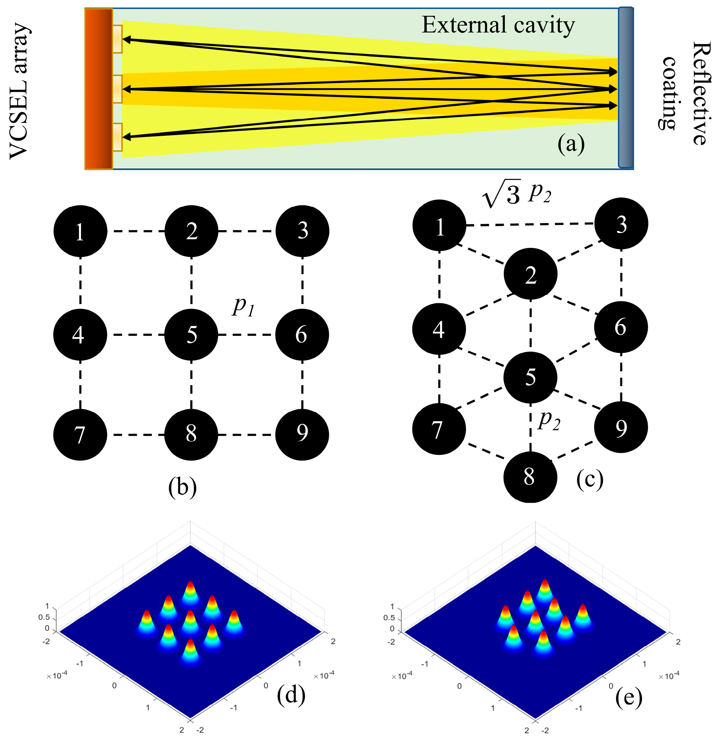
2. Mathematical Model Setting

For any two-dimensional distributed top-emitting external cavity VCSEL array source, the m-th element in the initial plane of the source is affected by the n-th element transmitting a round trip through the external cavity, and its coupling coefficient is expressed as [8,22]:
C m n = r = 0 , θ = π , π E n * ( r , θ , 2 z ) · E m ( r , θ , 0 ) r d r d θ ( r = 0 , θ = π , π | E n ( r , θ , 2 z ) | 2 r d r d θ ) 1 / 2 · ( r = 0 , θ = π , π | E m ( r , θ , 0 ) | 2 r d r d θ ) 1 / 2
where 2 z is the round-trip transmission distance through the external cavity and * is the complex conjugate. The source array composed of N elements is listed as element 1 to N, then the parallel-coupled coefficients among all elements can form the coupling matrix:
M p = [ C 11 C 1 N C M 1 C M N ]
If M = N, the eigenvalue βj of the matrix and its corresponding eigenvector Aj (j = 0, 1, 2, …, N) are satisfied:
M p A j = β j I A j
where I is the identity matrix for βj. Aj is the complex amplitude of the j-th supermode that the corresponding array can laser. According to the self-reproduction condition of VCSEL [27], combined with the influences of other elements in the array source plane for element m, the amplitude self-reproduction condition can be obtained:
R R b n = 1 N C m n · exp [ 2 ( Γ g α ) L e f f ] = 1
where R = ( R t + T t R e x 1 + R t R e x ) 2 is the composite reflectance [28] of the R t (the reflectance of p-DBR) and R e x (the reflectance of external cavity’s optical film), R b is the reflectance of n-DBR, Γ is the confinement factor, g is the gain threshold, α is the loss in the internal cavity, L e f f is the equivalent length of the internal cavity. By replacing Equations (2) and (3) with the above self-reproduction condition, the gain threshold condition of the j-th supermode can be obtained:
g j = ln ( 1 Re ( β j ) R b R ) / Γ · L e f f + α L e f f / Γ · L e f f
The distributions of the VCSEL array are shown in Figure 1.
A square array is a common distribution, while regular hexagonal array distribution improves plane utilization. If the array’s period, wavelength and other parameters are normalized by some methods [16] to measure the length of the external cavity, the regular hexagonal array’s complex amplitude change period is shorter than that of the square array in the range of diffraction coupling [19].

3. Numerical Simulation and Analysis

Using the 9-element square array and regular hexagonal array shown in Figure 1. As models, the following numerical simulation results were obtained using MATLAB. The general parameters of the models were set as shown in Table 1.

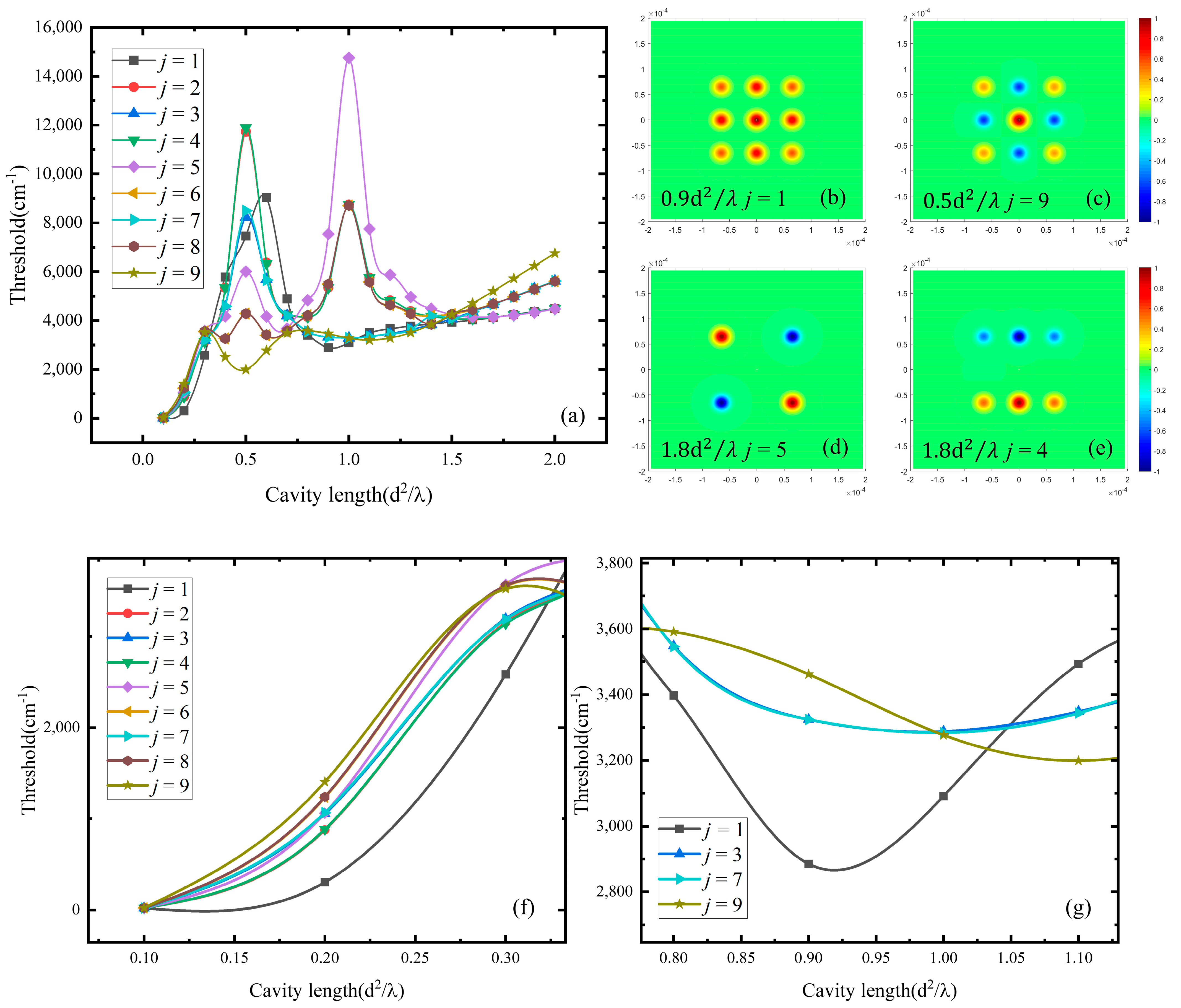
3.1. The Influence of Array Distribution on Supermode

The optic field of the 9-element array composed with the elements of transverse mode TEM00 at the duty ratio F = 0.4 was coupled to each VCSEL internal cavity through the round-trip diffraction feedback, and the changes of supermodes’ excitation thresholds of each order versus the length of the external cavity are shown in Figure 2a. In the range of 0.4 0.6 d 2 / λ , the highest order mode (j = 9) has a significantly lower threshold than other modes (approximately 500–2000 cm−1), and the near-field distribution of this supermode is shown in Figure 2c. In the range of 0.2 0.3 d 2 / λ , 0.8 1.0 d 2 / λ , the lowest order supermode (j = 1) has the lowest threshold with the threshold difference (shown in Figure 2f,g) of about 200–1000 cm−1 and the near-field distribution is shown in Figure 2b. However, in the range of 1.4 1.6 d 2 / λ , the threshold of the lowest order supermode (j = 1) has the lowest threshold, while the gain threshold difference is not enough to provide the threshold current difference, which is difficult to use as the external cavity length of the control supermode in the experiment. Therefore, the range of 1.1 2.0 d 2 / λ , is an interval that generates multiple supermodes, and it is shown the near-field amplitude distribution in the initial plane of the excitation supermodes at 1.8 d 2 / λ (the intermediate supermode j = 5 and j = 4) in Figure 2d,e. The amplitude of some elements of intermediate supermode is partially suppressed, which is much less than 1 × 10⁻¹ (assume the amplitude of the initial source is 1 without the external cavity coupling); that is, the total intensity has a certain gap compared to the highest-or the lowest order supermode. For example, the intensity of the intermediate supermode j = 6 at 1.2 d 2 / λ is only about 58% of that of the lowest supermode, and the far-field light spot distribution is also divergent.
As shown in Figure 1c, assuming p 1 = p 2 , the result of the regular hexagonal array can be different from the square array by solving the eigenvalues of the coupling matrix and obtaining the corresponding eigenvector. For example, there is no lowest supermode among the 9 types of supermodes that may be generated at 0.9 1.05 d 2 / λ , that is, there is no transverse mode with an identical relative phase among all the elements in the regular hexagonal array. In its place is a supermode in which the light intensity of some units is suppressed to zero, as shown in Figure 3a. The regular hexagonal array generates the lowest supermode from 0.15 d 2 / λ to 0.3 d 2 / λ . With the external cavity of the other lengths between 0.075 1.5 d 2 / λ , various high-order supermodes with the lowest thresholds are outputted separately or simultaneously, as shown in Figure 3a. As the above simulation results show, the optional external cavity length of the regular hexagonal array, such as 0.3 d 2 / λ (maximum gain threshold difference within the interval) to control the output of the lowest order supermode. The shorter external cavity control length interval relative to the square array demands more stringent requirements on the preparation process.

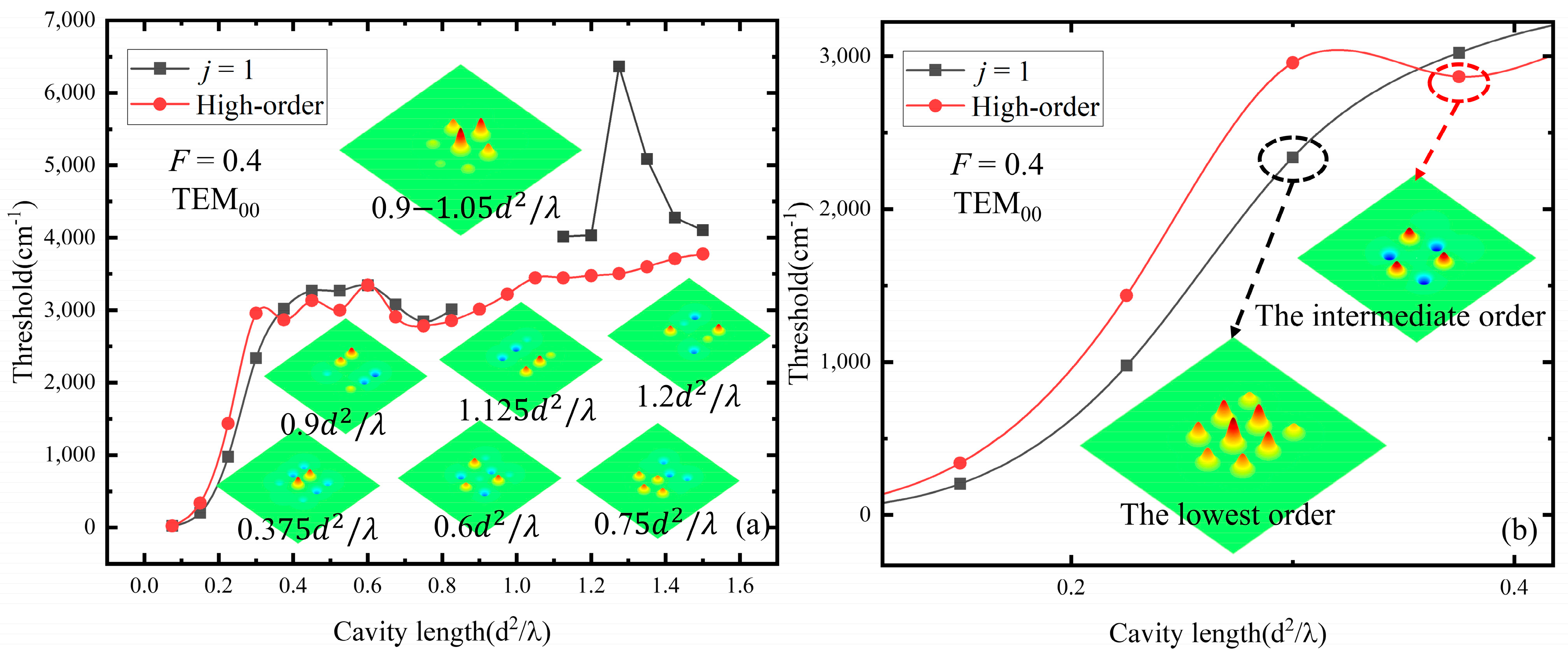
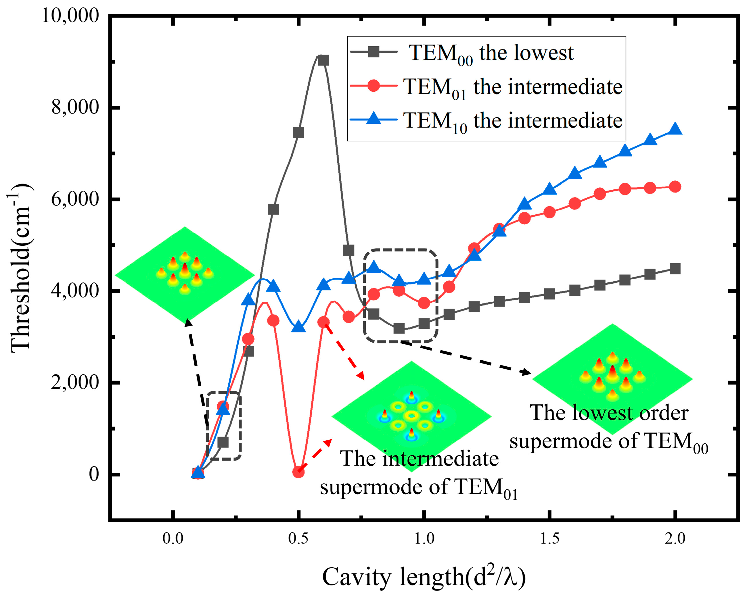
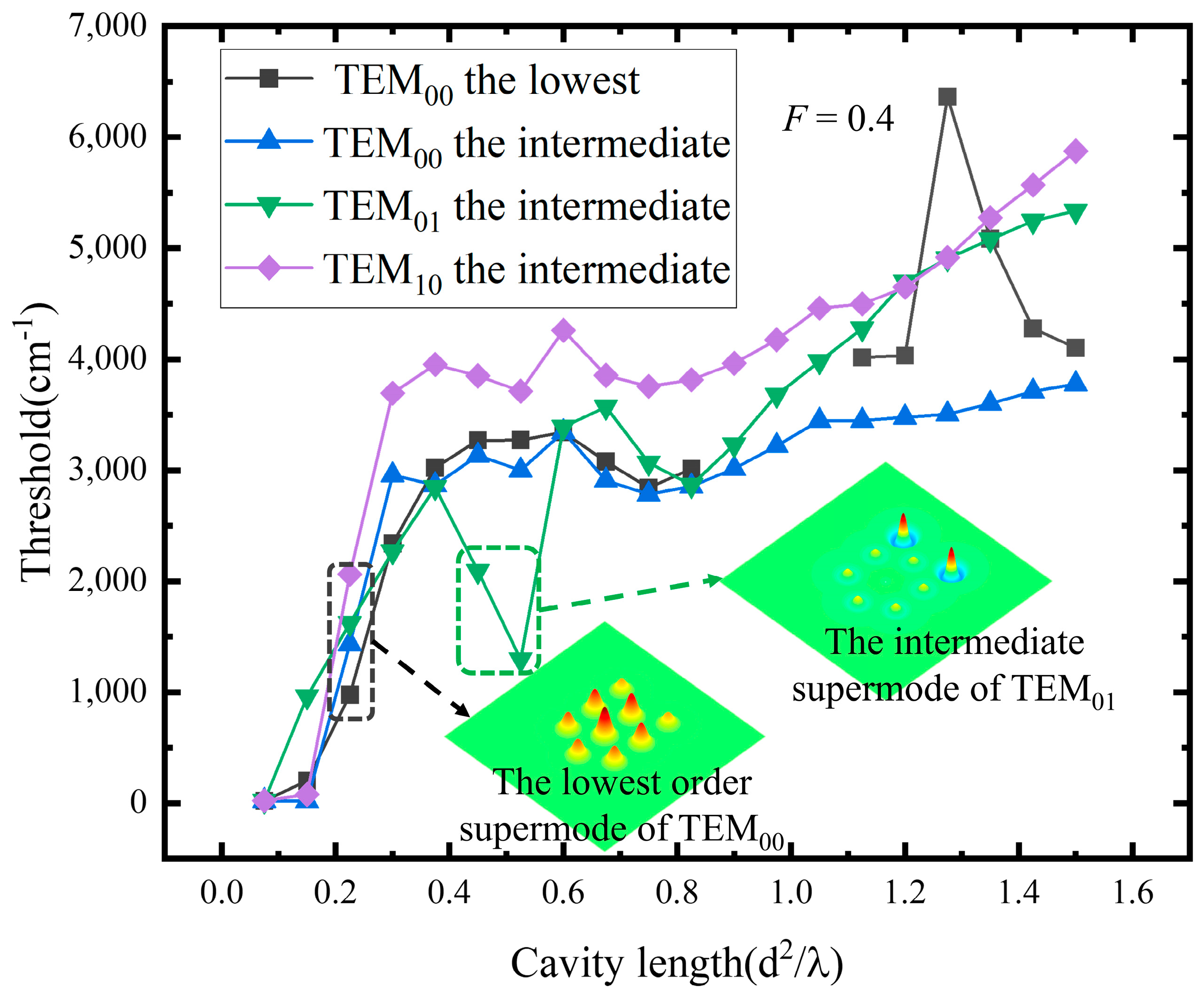
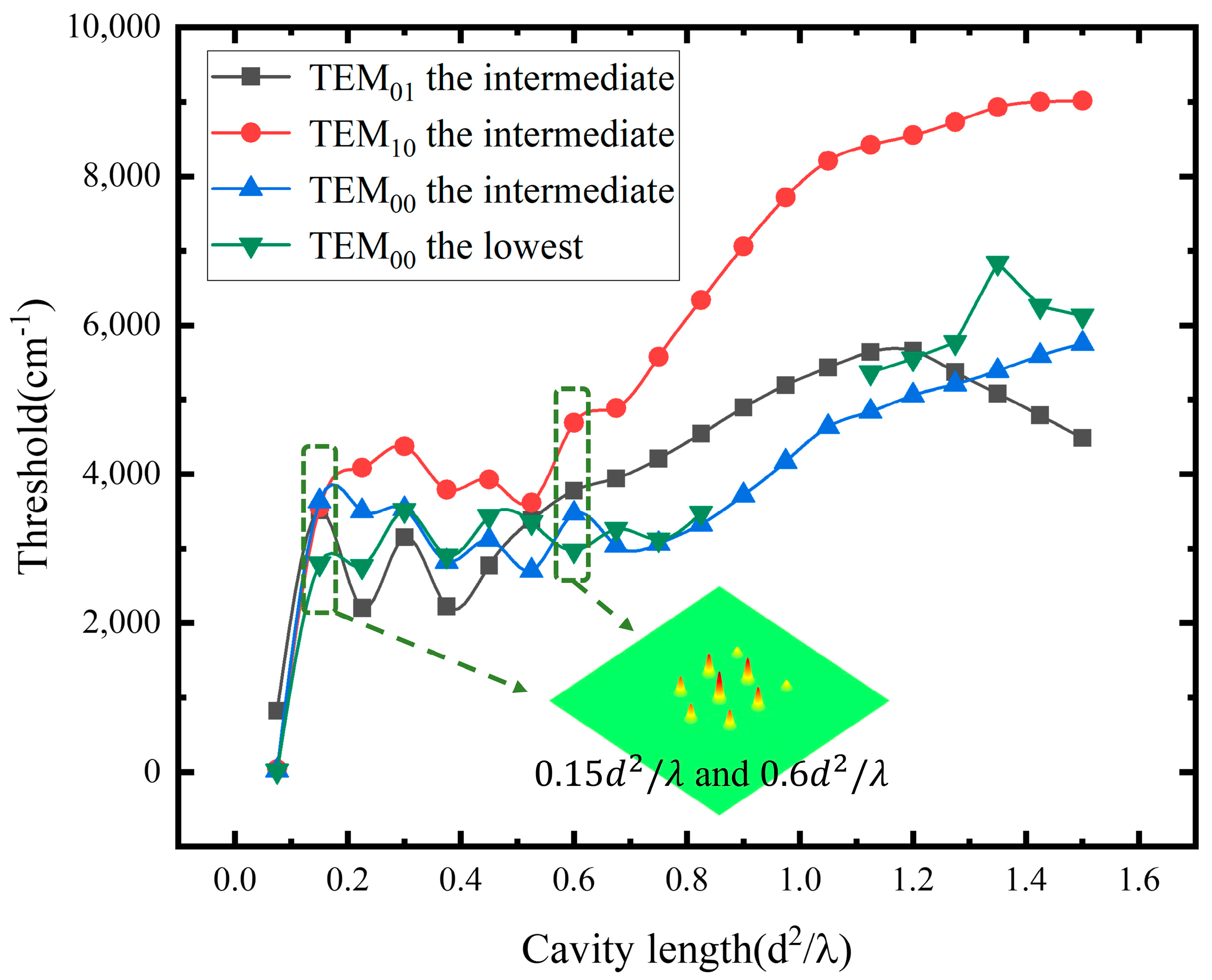
3.2. The Influence of Elements’ Transverse Mode on Supermode

A larger aperture of the VCSEL will bring a high-order transverse mode output. The coupling coefficient of the high-order transverse mode is different from the fundamental transverse mode in the coupling process of external cavity diffraction. The square array of TEM01 and TEM10 whose high-order transverse mode is the output of the element, is calculated by the external cavity coupling matrix, respectively, to obtain the curves of gain threshold versus the length of the external cavity. The results are shown in Figure 4. Combined with the simulation results in Section 3.1, the lowest supermode of TEM00 mode through the external cavity diffraction coupling in the interval of 0.2 0.3 d 2 / λ and 0.8 1.0 d 2 / λ has the lowest gain threshold for the square array and a length of 0.2 d 2 / λ and 0.8 1.0 d 2 / λ provides large threshold differences to control the supermode.
Considering the influence of the high-order transverse mode, the simulation results of supermodes’ threshold of the regular hexagonal array are shown in Figure 5. Under the condition of a large duty ratio (F = 0.4), the regular hexagonal array can still output the lowest supermode formed by TEM00 mode through the external cavity diffraction coupling at the cavity length of 0.225 d 2 / λ , but the high-order supermodes formed by TEM01 mode will be generated at 0.45 0.525 d 2 / λ . Moreover, the amplitude of most elements in the array is greatly suppressed.

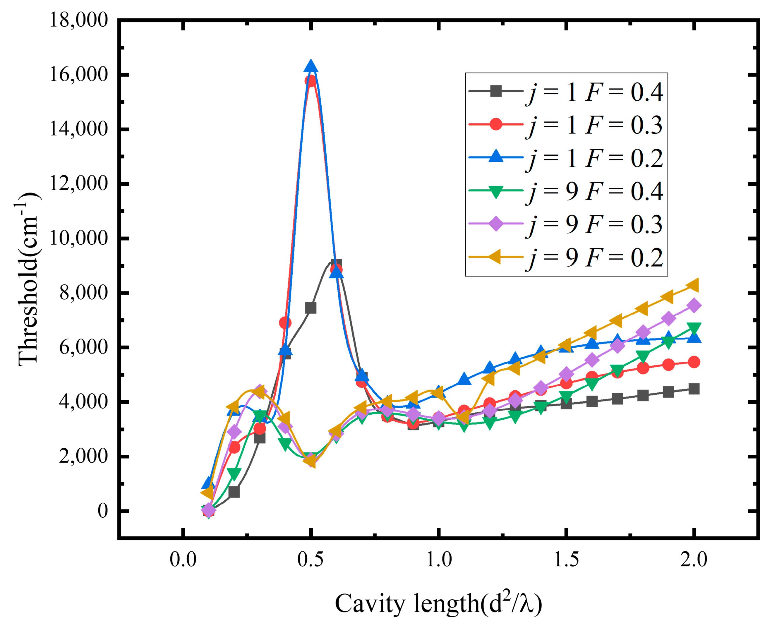
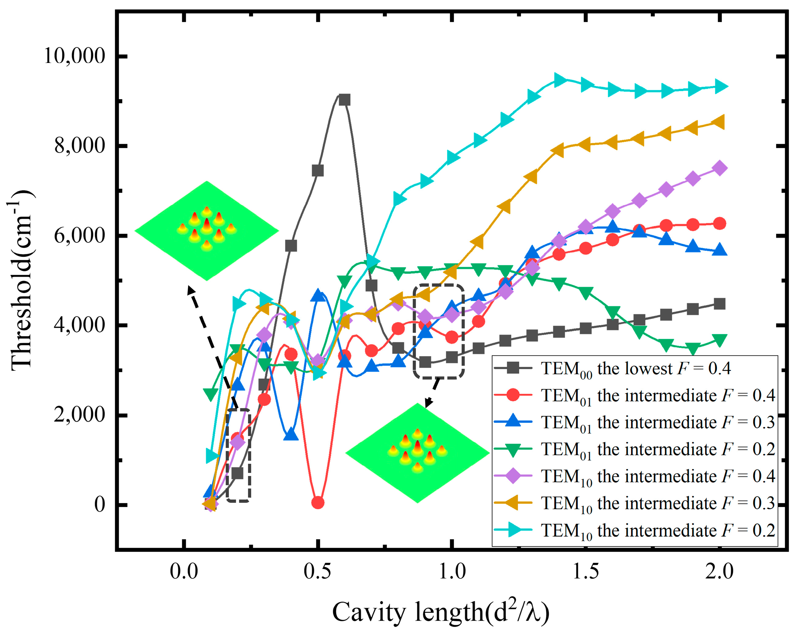
3.3. The Influence of Array’s Duty Ratio on Supermode

For the square array composed of the fundamental transverse mode, the influence brought by the change in this parameter is shown in Figure 6. Regard the mode as the lowest order supermode when j = 1 and the mode as the highest order supermode when j = 9, for example.
A larger array duty ratio, F, is conducive to the diffraction coupling of the external cavity and provides a lower threshold. As for the lowest supermode output of j = 1, composed of TEM00 mode obtained by the external cavity system, the influence of duty ratio F on the supermode threshold composed of high-order transverse mode elements versus the external cavity length obtained by simulation is shown in Figure 7.
In the coupling process of the external cavity diffraction of different high-order transverse modes, the divergent velocity of the spot is different, so the change of duty ratio F has a complex influence on the threshold of the high-order transverse mode array. However, for the square array, the output of the lowest supermode of fundamental transverse mode elements is still in the range of 0.9 1.0 d 2 / λ and the length of 0.2 d 2 / λ . For the regular hexagon array with a smaller duty ratio (as shown in Figure 8, F = 0.2), two large threshold differences (approximately 600–800 cm−1) at 0.15 d 2 / λ and 0.6 d 2 / λ allow the external cavity to control the output of the lowest order supermode composed of TEM00 elements.

4. Discussion

The change of array distribution mode and array element transverse mode will bring about the change of the outer cavity control range. The gain threshold of the supermode decreases with the increase in the array duty ratio. Based on the simulation results above, two kinds of VCSEL array output schemes for the lowest supermode consisting of the fundamental transverse mode are proposed, namely, a square array with a higher duty ratio and an external cavity length prepared of 0.2 d 2 / λ and the range of 0.9 1.0 d 2 / λ . The regular hexagonal array with a lower duty ratio and external cavity of 0.15 d 2 / λ and 0.6 d 2 / λ length prepared. Through the designs above, the spots concentrated on the center normal of the VCSEL array geometry can be obtained in the far field.

5. Conclusions

Proposing the parallel-coupled model of external cavity diffraction, this study numerically calculated the gain threshold of each supermode of a two-dimensional VCSEL array using MATLAB. The influences of array distribution, element transverse mode and array duty ratio on the threshold of VCSEL array’s supermode are analyzed. In order to control the supermode and elements’ transverse mode of the VCSEL array through the external cavity diffraction coupling, the square array with a larger duty ratio provides a wider length of control, namely the range of 0.9 1.0 d 2 / λ and the length of 0.2 d 2 / λ . A regular hexagonal array with a smaller duty ratio provides a shorter external cavity length, namely 0.15 d 2 / λ or 0.6 d 2 / λ . A shorter external cavity will reduce the absorption loss and output more optical power, but more precise control of cavity length during device preparation is required. The results of parallel-coupled simulation and analysis in this study have a reference significance for the output of fundamental transverse mode of lowest supermode for VCSEL array controlled by external cavity. It also provides a theoretical reference for obtaining VCSEL coherent array laser beams with high power and near diffraction limits.

Author Contributions

Conceptualization, J.D. and C.W.; methodology, J.D. and C.W.; software, C.W.; validation, J.D., C.W. and W.L.; formal analysis, C.W. and W.L.; investigation, C.W.; resources, J.D.; data curation, C.W.; writing—original draft preparation, C.W.; writing—review and editing, J.D., W.L. and S.M.; supervision, J.D. and Z.W. All authors have read and agreed to the published version of the manuscript.

Funding

This research received no external funding.

Institutional Review Board Statement

Not applicable.

Informed Consent Statement

Not applicable.

Data Availability Statement

Not applicable.

Conflicts of Interest

The authors declare no conflict of interest.

References

  1. Lott, J.A. Vertical Cavity Surface Emitting Laser Diodes for Communication, Sensing, and Integration. In Semiconductor Nanophotonics; Springer: Cham, Switzerland, 2020. [Google Scholar]
  2. Wang, C.; Geske, J.; Garrett, H.; Cardellino, T.; Klemer, D. Large-Area High-Power VCSEL Pump Arrays Optimized for High-Energy Lasers. Laser Technol. Def. Secur. VIII 2012, 8381, 41. [Google Scholar]
  3. Mateus, C.F.; Barbosa, C.L. Harsh Environment Temperature and Strain Sensor Using Tunable VCSEL and Multiple Fiber Bragg Gratings. In Proceedings of the 2007 SBMO/IEEE MTT-S International Microwave and Optoelectronics Conference, Salvador, Brazil, 29 October–1 November 2007. [Google Scholar]
  4. Tsai, T.H.; Ahsen, O.O.; Lee, H.C. Ultrahigh Speed Endoscopic Swept Source Optical Coherence Tomography Using a VCSEL Light Source and Micromotor Catheter. Endosc. Microsc. IX Opt. Tech. Pulm. Med. 2014, 8927, 34–39. [Google Scholar]
  5. Hibbs-Brenner, M.K.; Johnson, K.L.; Bendett, M. VCSEL Technology for Medical Diagnostics and Therapeutics. Photons Neurons 2009, 7180, 14. [Google Scholar]
  6. Seurin, J.F.; Xu, G.; Khalfin, V.; Miglo, A.; Wynn, J.D.; Pradhan, P.; Ghosh, C.L.; D’Asaro, L.A. Progress in High-Power High-Efficiency VCSEL Arrays. Vert. Cavity Surf. Emit. Lasers XIII 2009, 7229, 19–29. [Google Scholar]
  7. Wang, C.; Li, C.; Dai, J.; Wang, Z. Study on In-Chip Phase Locked High Brightness Bottom Emitting Talbot-VCSELs Array. In Proceedings of the AOPC 2020: Advanced Laser Technology and Application, Beijing, China, 30 November–2 December 2020; SPIE: Bellingham, WA, USA, 2020. [Google Scholar]
  8. Ho, E.; Koyama, F.; Iga, K. Effective Reflectivity from Self-Imaging in a Talbot Cavity and Its Effect on the Threshold of a Finite 2-D Surface Emitting Laser Array. Appl. Opt. 1990, 29, 5080–5085. [Google Scholar] [CrossRef]
  9. Seurin, J.F.; Ghosh, C.L.; Khalfin, V.; Miglo, A.; Xu, G.; Wynn, J.D.; Pradhan, P.; D’Asaro, L.A. High-Power High-Efficiency 2D VCSEL Arrays. Vert. Cavity Surf. Emit. Lasers XII 2008, 6908, 45–58. [Google Scholar]
  10. Guenter, J.K.; Lei, C.; Zhou, D.; Seurin, J.F.; Xu, G.; Miglo, A.; Li, D.; Wang, Q.; Sundaresh, M.; Wilton, S. Progress on Vertical-Cavity Surface-Emitting Laser Arrays for Infrared Illumination Applications. Ber. Der. Bunsenges. Für. Phys. Chem. 2014, 97, 172–176. [Google Scholar]
  11. Wei, S.M.; Xu, C.; Deng, J.; Zhu, Y.X.; Mao, M.M.; Xie, Y.Y.; Xu, K.; Cao, T.; Liu, J.C. Single-Fundamental-Mode 850 Nm Surface Relief VCSEL. Chin. Phys. Lett. 2012, 29, 1028–1032. [Google Scholar] [CrossRef]
  12. Shinada, S.; Koyama, F.; Nishiyama, N.; Arai, M.; Iga, K. Single High-Order Transverse Mode 850 Nm VCSEL with Micromachined Surface Relief. In Proceedings of the Conference on Lasers & Electro-Optics, Baltimore, MD, USA, 11 May 2001. [Google Scholar]
  13. Alias, M.S.; Shaari, S.; Leisher, P.O.; Choquette, K.D. Single Transverse Mode Control of VCSEL by Photonic Crystal and Trench Patterning. Photonics Nanostruct. 2010, 8, 38–46. [Google Scholar] [CrossRef]
  14. Kasten, A.M.; Siriani, D.F.; Hibbs-Brenner, M.K.; Johnson, K.L.; Choquette, K.D. Beam Properties of Visible Proton-Implanted Photonic Crystal VCSELs. IEEE J. Sel. Top. Quantum Electron. 2011, 17, 1648–1655. [Google Scholar] [CrossRef]
  15. Okur, S. High-Power VCSEL Arrays with Customized Beam Divergence for 3D-Sensing Applications. Vert. Cavity Surf. Emit. Lasers XXIII 2019, 10938, 61–67. [Google Scholar]
  16. Kandidov, V.P.; Kondrat’ev, A.V. Collective Modes of Laser Arrays in Talbot Cavities of Various Geometries. Quantum Electron. 1997, 27, 234. [Google Scholar] [CrossRef]
  17. Kandidov, V.P.; Kondrat’ev, A.V. Influence of the Talbot Cavity Selectivity on the Evolution of Collective Operation of Diffraction-Coupled Laser Arrays. Quantum Electron. 1998, 28, 972. [Google Scholar] [CrossRef]
  18. Kandidov, V.P.; Kondrat’ev, A.V.; Surovitskii, M.B. Collective Modes of Two-Dimensional Laser Arrays in a Talbot Cavity. Quantum Electron. 2007, 28, 692. [Google Scholar] [CrossRef]
  19. Kandidov, V.P.; Kondrat’ev, A.V.; Surovitskii, M.B. Collective Modes of 2D Laser Array with Diffraction Coupling. In 6th International Conference on Industrial Lasers and Laser Applications ‘98; SPIE: Bellingham, WA, USA, 1999; Volume 3688, pp. 24–31. [Google Scholar]
  20. Ma, Y.; Lan, T.; Wang, X.; Ruan, R.; Cao, Y.; Dai, J.; Wang, Z. Phase-Locking Dynamics of a 2D VCSEL Hexagonal Array with an Integrated Talbot Cavity. Opt. Express 2022, 30, 9892–9903. [Google Scholar] [CrossRef]
  21. Shichijo, T.; Miyamoto, T. Rate Equation-Based Numerical Analysis of Mutual Injection for Phase Locked 2D-VCSEL Array Using Talbot Effect. Jpn. J. Appl. Phys. 2019, 58, SJJC01. [Google Scholar] [CrossRef]
  22. Khajavikhan, M.; Leger, J.R. Modal Theory of Coupled Resonators for External Cavity Beam Combining. In Coherent Laser Beam Combining; Wiley-VCH Verlag: Weinheim, Germany, 2013. [Google Scholar]
  23. Leger, J.R. Lateral Mode Control of an AlGaAs Laser Array in a Talbot Cavity. Appl. Phys. Lett. 1989, 55, 334–336. [Google Scholar] [CrossRef]
  24. Butler, J.K.; Ackley, D.E.; Botez, D. Coupled-Mode Analysis of Phase-Locked Injection Laser Arrays. Appl. Phys. Lett. 1984, 44, 935. [Google Scholar] [CrossRef] [Green Version]
  25. Mehuys, D.; Streifer, W.; Waarts, R.G.; Welch, D.F. Modal Analysis of Linear Talbot-Cavity Semiconductor Lasers. Opt. Lett. 1991, 16, 823–825. [Google Scholar] [CrossRef]
  26. Fader, W.J.; Palma, G.E. Palma Normal Modes of N Coupled Lasers. Opt. Lett. 1985, 10, 381–383. [Google Scholar] [CrossRef]
  27. Michalzik, R. VCSELs: Fundamentals, Technology and Applications of Vertical-Cavity Surface-Emitting Lasers (Springer Series in Optical Sciences); Springer: Berlin/Heidelberg, Germany, 2013; Volume 166, ISBN 978-3-642-24985-3. [Google Scholar]
  28. Zhou, D.; Seurin, J.F.; Xu, G.; Pu, Z.; Ghosh, C. Progress on High-Power High-Brightness VCSELs and Applications. Vert. Cavity Surf. Emit. Lasers XIX 2015, 9381, 91–102. [Google Scholar]
Figure 1. (a) Diagram of parallel-coupled external cavity VCSEL array; (b) position distribution of initial plane of square array; (c) position distribution of initial planar of regular hexagonal array; (d) the initial planar amplitude distribution of the square array; (e) initial planar amplitude distribution of regular hexagonal array.
Photonics 10 00115 g001
Figure 2. (a) Gain thresholds of each order supermode obtained by parallel-coupled calculation of the external cavity diffraction of the square array composed of TEM00 transverse mode elements with the duty ratio F = 0.4; (b) the lowest order mode’s near-field distribution (j = 1); (c) the highest mode’s near-field distribution (j = 9); (d) the intermediate supermode’s near-field distribution (j = 5); (e) the intermediate supermode’s near-field distribution (j = 4); (f) enlarged view of the part of 0.1 0.3 d 2 / λ ; (g) enlarged view of the part of 0.8 1.1 d 2 / λ .
Photonics 10 00115 g002
Figure 3. (a) The change of the threshold of the lowest order supermode (hexagonal array composed of TEM00 elements) and the minimum threshold of other intermediate supermodes versus the external cavity length, and the amplitude distributions of the near-field of various possible simultaneous production of intermediate supermodes at some planes with the duty ratio F = 0.4; (b) enlarged view of the cavity length of 0.15 0.5 d 2 / λ and the near-field distributions of the lowest supermode and the intermediate supermode.
Photonics 10 00115 g003
Figure 4. The thresholds of supermodes generated by the TEM01 and TEM10 high-order transverse mode element arrays and the thresholds of the supermode with the lowest mode square array generated by the TEM00 transverse mode versus the length of external cavity from 0.1 2.0 d 2 / λ .
Photonics 10 00115 g004
Figure 5. The thresholds of the lowest supermode and higher-order supermodes (the minimum values) with elements of TEM00, and the thresholds of supermodes with elements of TEM01 and TEM10 which are the regular hexagonal arrays versus the length of external cavity of 0.075 1.5 d 2 / λ .
Photonics 10 00115 g005
Figure 6. The changes of thresholds relative to duty ratio F of lowest supermode and highest order supermode of TEM00 mode array versus the external cavity length of 0.1 2.0 d 2 / λ .
Photonics 10 00115 g006
Figure 7. The curves of the minimum thresholds among supermodes of the high-order transverse mode (TEM01 and TEM10) array which may be generated with the different duty ratio F and the lowest supermode threshold of the TEM00 array versus the external cavity length from 0.1 2.0 d 2 / λ .
Photonics 10 00115 g007
Figure 8. The changes of the minimum thresholds among supermodes of the high-order transverse mode (TEM01 and TEM01) array which may be generated with the duty ratio F = 0.2 and the lowest mode threshold of the TEM00 transverse mode array versus the external cavity length of 0.075 1.5 d 2 / λ .
Photonics 10 00115 g008
Table 1. Parameters of the models.
ParameterValue
Wavelength (μm)0.98
Γ2.055
α (cm−1)4000
Rt0.995
Rb0.999
Rex0.85
p (μm)65
Leff (μm)1.3
Disclaimer/Publisher’s Note: The statements, opinions and data contained in all publications are solely those of the individual author(s) and contributor(s) and not of MDPI and/or the editor(s). MDPI and/or the editor(s) disclaim responsibility for any injury to people or property resulting from any ideas, methods, instructions or products referred to in the content.

