Abstract
We provide a simple analysis based on ray optics and Dirac notation for 1D (one-dimensional) and 2D (two-dimensional) non-diffracting modes in the cosine profile, which are often called Cosine beams. We explore various kinds of structured modes formed by the superposition of two 1D Cosine beams. We then went on to understand the properties of the Bessel beams in terms of Cosine beams. For the first time, we report on the generation of three-dimensional tunable needle structures based on the interference of 1D Cosine beams. These size-tunable optical needles can have multiple advantages in material processing. Also, we report, for the first time, on the Talbot effect in Cosine beams. Straightforward mathematical calculations are used to derive analytical expressions for Cosine beams. The present method of demonstrating Cosine beams may be utilized to understand other structured modes. The Dirac notation-based interference explanation used here can provide new researchers with an easy way to understand the wave nature of light in a fundamental aspect of interferometric experiments as well as in advanced-level experiments such as beam engineering technology, imaging, particle manipulation, light sheet microscopy, and light–matter interaction. We also provide an in-depth analysis of similarities among Cosine, Bessel, and Hermite–Gaussian beams.
1. Introduction
The transverse structuring of a conventional Gaussian-shaped laser beam with phase modulation has produced a variety of structured modes and has seen tremendous applications in fundamental and applied optics. The suitable names for these beams are assigned based on their properties (phase, amplitude, and intensity) following the mathematical functions. For instance, the Laguerre–Gaussian (LG) beam, Hermite–Gaussian (HG) beam, Ince–Gaussian (IG) beam, Bessel beam, Cosine beam, and Airy beam can be represented with respective mathematical functions of the Laguerre polynomial, Hermite polynomial, Ince polynomial, Bessel polynomial, cosine function, and Airy function [1,2,3,4,5,6,7].
Among all structured laser beams, one-dimensional (1D) Cosine beams have a simple structure, and they can be easily synthesized in any optical laboratory with readily available diffractive optical elements such as Fresnel biprism, mirrors, and beam splitters [8,9]. It has recently been reported that Cosine beams can be generated using resonant metasurfaces [10]. Some of the works have been carried out on the modulation of Cosine beam characteristics to enhance their user-friendly nature for the scientific community. For instance, the generation and characterization of higher-order Cosine beams [11], truncation of Cos beams [12], creation of apertured Cos beams [13], generation of Cosine–Gauss beams and their propagation through apertured paraxial ABCD optical systems [14], and rectification of Cosine Gaussian beam [15]. The properties like self-healing and non-diffraction nature [11,16] of Cosine beams make them utilized in fundamental and applied optics. To name a few, various kinds of Cosine beams with and without apodization are used in light-sheet microscopy [17], interaction with uniaxial crystals [18], the interaction of linear and nonlinear media [19,20], in periodic potential optical lattices [21], the study of spherical particles [22], optical wireless communication [23], and plasmonics [24].
On the other hand, the generation, characterization, and applications of various kinds of structured laser modes are mathematically understood by formulating them with ray optics and wave optics. In terms of understanding of the nature of light, ray optics is a very simplified method with multiple limitations, but wave optics have several advantages with complex mathematical functions [25]. Furthermore, two other methods can be utilized to understand the light, which are matrix and Dirac notations [26]. The replacement of the general wave function representation with Dirac notation in the analysis of optical fields simplifies our understanding of light.
Here, we explore the properties of the Cosine beam in a full-fledged way through Dirac notation and ray optics. We first demonstrate how individual waves are involved in the superposition of optical beams to produce 1D and two-dimensional (2D) Cosine beams. Indeed, we interpreted their non-diffraction and self-healing properties. The procured results for 1D and 2D Cosine beams further motivated us to consider the superposition of two 1D Cosine beams and their resulting series of optical needle arrays. Our analysis extends to Bessel beams and examines the similarities and differences between Cosine beams, Bessel beams, and HG beams.
In this work, we attempted to explain structured laser beams with Dirac notation for the first time. To provide a clear-cut idea of the advantage and ease of Dirac notation for the explanation of structured beams, we start our analysis with a simple 1D Cosine beam supported by ray optics. Next, we extend the same analysis to realize three-dimensional tunable optical needles via the interference of 1D Cosine beams. As part of this, we observe for the first time that Cosine beams can also produce the Talbot effect, which can be used in bio-imaging techniques like light-sheet microscopy.
2. One-Dimensional Cosine Beam
The generation of a 1D Cosine beam occurs through the superposition of two plane waves that obliquely propagate, and the subtended angle between them is 2θ, which can be understood through the ray optics representation depicted in Figure 1a. The interference takes place on the yz-plane, with their bisecting axis being the z-axis. Thus, the optical axis of the Cosine beam is given by the bisecting axis (z-axis) of the two plane waves. Here, the Cosine beam forms only in the overlapping region of the two waves, and its range and width depend on the respective size of the interfering waves and the angle of interference [11]. As shown in Figure 1b, the characteristics of the Cosine beam can be interpreted in terms of the properties of the interfering waves. When the two interfering plane waves are polarized perpendicular to the plane of interference, the electric fields of both waves oscillate in the same direction, and the interpretation of interference is quite easy. However, when both plane waves have the same polarization direction but an angle ϕ with respect to the plane of interference, i.e., θ and ϕ directions are orthogonal to each other, the situation becomes more complex. Here, θ is considered from the bisecting axis of the interfering beams (z-axis), whereas polarization of the optical field is inclined at an angle ϕ with reference to the x-axis, which is perpendicular to the plane of interference. The optical field projections along the Cartesian coordinates can be understood from Figure 1c. The state of the k-vector and E-vector along x, y, and z coordinates for wave-1 and wave-2 are provided in Table 1. The result of counter-propagating k-vectors, ky and ky′, produces a standing wave interference along the y-axis, and the outcome of co-propagating k-vectors, kz and kz′, results in the propagation vector of the Cosine beam along the z-axis.

Figure 1.
Ray optics representation of Cosine beam: (a) formation of the Cosine beam through the interference of two plane waves, (b) pictorial interpretation of optical waves’ amplitude and propagation vector (dashed arrows are projections), and (c) projection of the optical field along the three axes of the Cartesian coordinate system.

Table 1.
The propagation vectors and optical field amplitudes of interfering plane waves along x, y, and z directions during the 1D Cosine beam generation.
The generation of a Cosine beam through the interference of two plane waves can be easily understood using bra-ket ⟨∙|∙⟩ notation. As shown in Figure 1a, to distinguish the interfering waves, we use un-primed coordinates for plane wave-1 and primed coordinates for plane wave-2. The states of the two interfering plane waves are given by
and
Here, the three-dimensional polarization states |β⟩ and |β′⟩ of respective plane waves are given by
Here, |a⟩, |b⟩, and |c⟩ are polarization states along x, y, and z coordinates, respectively. The orthogonality of the polarization states provides the following conditions: ⟨a|a⟩ = ⟨b|b⟩ = ⟨c|c⟩ = 1 and ⟨a|b⟩ = ⟨b|c⟩ = ⟨c|a⟩ = 0. Consequently, the inner product of states |β⟩ and |β′⟩ is given by ⟨β|β⟩ = |E|2, ⟨β′|β′⟩ = |E′|2, ⟨β|β′⟩ = E*E′, and ⟨β′|β⟩ = EE′*.
It is a well-known statement that in the interference of two collinearly propagating beams, the interference visibility decreases with an increasing angle between the polarization states of individual beams, and it becomes zero when the angle is 90°. In the present context, even though the optical oscillations of two interfering beams make a certain angle with each other due to their cross-propagation, the visibility of interference is independent of this angle. Indeed, the projection of two interfering optical fields along the three Cartesian coordinates has the same amplitude (see Table 1). The angular separation between the two polarization states results from the angular separation created between the propagation vectors. It can be inferred from this scenario that the angular separation of the electric field oscillations results from the angular separation of light beams having a single plane of polarization, causing no effect on the interference.
From Equation (1), the state of a 1D Cosine beam can be written in terms of states |α⟩ and |α′⟩ of interfering beams as
and it is equivalent to the general electric field amplitude expression of a 1D Cosine beam, which is given by
The intensity distribution in the 1D Cosine beam, given by the inner product of the Dirac state provided by Equation (3) with setting up E = E′, is given by
As shown in Figure 2, 1D non-diffracting beams with a cosine envelope can be generated in the experimental laboratory with simple and low-cost experimental configurations based on either amplitude division [Figure 2a] or wave-front division [Figure 2b] interferometric techniques. In the amplitude division interferometer, a single collimated laser beam can be equally divided into two laser beams using a 50:50 beam splitter. We can make these two laser beams interfere with the aid of a single reflective mirror. The interference produced in the overlapping region of two beams results in a 1D Cosine beam. The second method of generation, based on wave-front division, can be experimentally realized by illuminating a collimated laser beam on a Fresnel biprism. The biprism, with base angle α, divides the circular-shaped laser beam into two semi-circular beams propagating at an angle θ = (n − 1) α with the optical axis. Here, the refraction property of the biprism enforces the individual waves of the incident collimated laser beam into cross-propagation with respect to the optical axis. The range and size of the Cosine beam depend on the spot size of interfering beams, w, and the interfering angle, θ. Even though we use identical input beams in both methods, the cross-sectional intensity distribution of the corresponding Cosine beams is different because the method of generation is different.
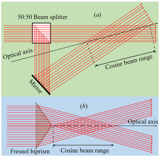
Figure 2.
Schematic experimental diagrams for Cosine beam generation: (a) beam splitter and mirror configuration for Cosine beam generation and (b) Fresnel biprism-based Cosine beam generation.
The phase and intensity distributions in the biprism-based 1D Cosine beam can be understood through Figure 3 for a plane wave consideration. The linear phase change of the biprism in the y-direction and the corresponding transverse intensity of the output 1D Cosine beams are presented in respective Figure 3a,b. The transverse phase variation of the biprism produces a constant periodic phase throughout the laser beam propagation, and as a result, the transverse energy distribution is in the form of a cosine function. For a better understanding of the correlation between the biprism and the characteristics of the Cosine beam, we have plotted the line profile of the biprism’s phase and the Cosine beam’s phase, amplitude, and intensity on a single graph, as depicted in Figure 3c.
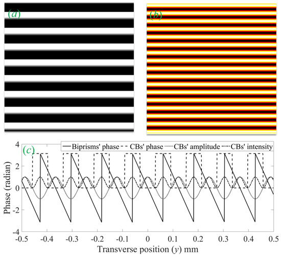
Figure 3.
Properties of the Cosine beam generated with a Fresnel biprism of base angle α = 1° at 640 nm wavelength: (a) phase introduced by the biprism to the incident laser beam to produce Cosine beam, (b) transverse intensity distribution of Cosine beam, and (c) line profiles of the biprism and the Cosine beam (amplitude and intensity of Cosine beam normalized to one).
2.1. Intensity Distribution of One-Dimensional Cosine Beam along x, y, and z Coordinates
The angular propagation of individual waves in the Cosine beam with respect to its optical axis leads to possible non-zero electric field components along the x, y, and z directions. Following the condition E = E′, the state of the 1D Cosine beam provided by Equation (3) can be expressed in terms of x, y, and z states as
and
The inner product of Equation (6a–c) with Equation (3) produces the electric field intensities along the x, y, and z directions and are
and
From the above Equations, we can understand that the optical field components along the longitudinal and transverse directions depend on the polarization angle, ϕ, and interfering angle, 2θ. For (ϕ, θ) = (70°, 15°), the intensity components of the Cosine beam along the three coordinates, x, y, and z, are given in Figure 4. The non-uniform intensity distribution of the 1D Cosine beam along the three directions is a result of (ϕ, θ). This effect can be very well understood under special conditions of (ϕ, θ). For that, let us suppose the peak intensity of the Cosine beam is Io, which is equivalent to 4I in Equation (7). For extreme conditions: (ϕ, θ) = (0°, θ) ⇒ (Ix, Iy, Iz) = (Io, 0, 0) and (ϕ, θ) = (90°, θ) ⇒ (Ix, Iy, Iz) = (0, Iocos2θ, Iosin2θ). The Iz is the maximum of Iz = Io/2 for (ϕ, θ) = (90°, 45°) and zero for (ϕ, θ) = (0°, θ). For angles (ϕ, 0 < θ < π/4), Iz follows the inequality, 0 < Iz < Io/2. The longitudinal component, Iz, is negligible compared to the intensity pair (Ix, Iy) for θ < 5°, irrespective of ϕ value. Hence, for a few degrees of interfering angle, the effect of Iz can be successfully neglected in any light–matter interaction.
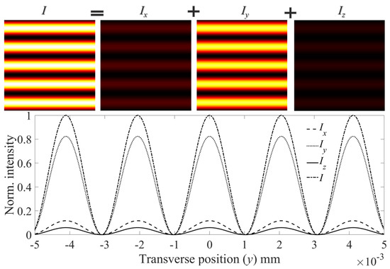
Figure 4.
Cross-sectional intensity components of the Cosine beam in the longitudinal and transverse directions are presented in the first row, and corresponding line profiles are plotted in the second row.
2.2. Properties of One-Dimensional Cosine Beam
The 1D Cosine beams have one-dimensional non-diffraction and self-healing properties in the plane of interference owing to the individual waves’ cross-propagation in an ‘X’ shape. The energy distribution in the overlapping region of cross-propagation is guided by the interference minima. Hence, without the loss of diffraction property of the wave, the energy distribution in the Cosine beam is free of diffraction. In addition to diffraction-free propagation, 1D Cosine beams have a self-healing property within their plane of incidence. It is also worth noticing that the 1D Cosine beam lacks any self-healing property perpendicular to its plane of incidence due to the absence of cross-propagation of waves in that direction. Therefore, 1D Cosine beams can only self-heal for line objects that are placed in the plane of incidence/plane of interference. The self-healing property of a 1D Cosine beam can be understood through ray optics, as shown in Figure 5. For line object obstacles, we can see a shadow in a certain region of the Cosine beam, and this shadow depends on the length of the object normal to the optical axis beam [11]. The unblocked cross-propagating waves due to the line object produce a Cosine beam both before the obstacle and after the shadow region. The fringe visibility [η = (Imax − Imin)/(Imax + Imin)] of the Cosine beam is at its maximum value, η = 1, predominantly for plane wave superposition.
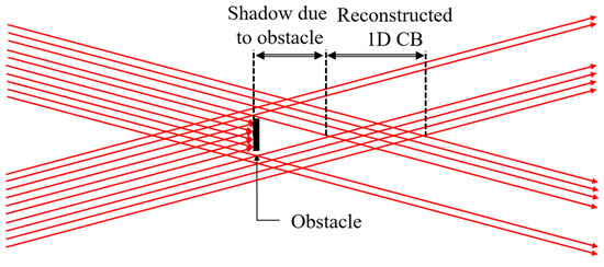
Figure 5.
Visualization of self-healing in the 1D Cosine beam through ray representation.
2.3. Real Cosine Beams
All mathematical expressions and discussions for the Cosine beam presented above are with due consideration of constant electric field amplitude E provided by the infinite extent of the plane wave. However, this kind of ideal Cosine beam is not realizable in experimental laboratories owing to its infinite extent. In real beams, the transverse intensity distribution is subject to transverse phase distribution, as we discussed in the introduction [1,2,3,4,5,6,7]. Hence, the transverse intensity and phase distribution in the Cosine beam are encumbered with the properties of superposed laser beams. It is possible to understand real Cosine beams through the truncation of Cosine beams. Depending on the interfering beams, we can apodize the Cosine beam, and we can create various types of Cosine beams, viz., Cosine–Gauss/Cos–Gauss (CG) beam [19], Cosine–Hermit–Gauss (CHG) beam [11], and Super–Gaussian–Cosine (SGC) beam [7]. As shown in Figure 6, the superposition of two Gaussian beams and the superposition of two HG beams are utilized to generate the respective CG beam and CHG beam based on the method given in Figure 2a. The optical field amplitude formed as a result of superposition can be written in terms of individual field amplitudes as E = E(x, y + y0, z) + E′(x, y − y0, z) and y0 = z tanθ. In a similar fashion, we can generate the Cosine–Ince–Gauss beam and Cosine–Laguerre–Gauss beam. The conspicuous non-uniform intensity in real laser modes produces Cosine beams with position-dependent fringe visibility. Therefore, the condition E = E′ is no longer valid in real beams, and the position-dependent fringe visibility can have all its values, i.e., 0 ≤ η (r, z) ≤ 1. The fringe visibility is equal to one near the optical axis, and it decreases with increasing transverse position of the beam. The position-dependent fringe visibility in real beams can be seen unquestionably in Figure 6.
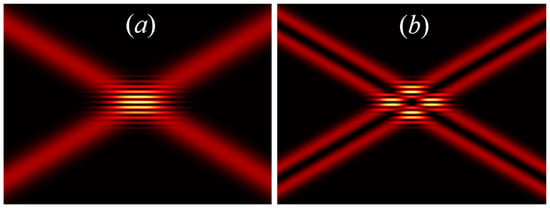
Figure 6.
1D Cosine beam formed as a result of cross-interference of two beams provided by the experimental configuration shown in Figure 2a: (a) Cosine–Gaussian beam in the presence of superposition of two Gaussian beams, and (b) Cosine–Hermite–Gauss beam under the superposition of two HG01 modes (here, θ = 5°).
3. Two-Dimensional Cosine Beam
The 2D Cosine beam in bra-ket notation is a mixed state, and it is formed by the product of two pure states of 1D Cosine beams. The two 1D Cosine beams must have the same optical axis with the orthogonal plane of incidence. The state of the 2D Cosine beam is given by |Ψ⟩ = |ψx⟩|ψy⟩. Here, the 1D Cosine beam with the plane of incidence in the xz-plane is mathematically represented as
and the state of the 1D Cosine beam with the plane of incidence in the yz-plane is represented as
The 2D Cosine beam state |Ψ⟩ in Dirac notation is equivalent to the general optical field amplitude expression of the 2D Cosine beam given by [18]
Here, states |βi⟩ and |β′i⟩ are functions of θx, ϕ in the xz-plane and are functions of θy, ϕ in the yz-plane (detailed information can be found in Appendix A). The intensity distribution in the 2D Cosine beam is given by the inner product of its Dirac state. Each ket state’s inner product with its corresponding bra state is given by
From Equations (3) and (10), we can obtain the Dirac product as
It is noted that |Ψ⟩ can further written as |Ψ⟩ = |ψxψy⟩ instead of |Ψ⟩ = |ψx⟩|ψy⟩. Here, the Equation |Ψ⟩ = |ψxψy⟩ is more complex than |Ψ⟩ = |ψx⟩|ψy⟩; however, both equations provide the same result, as shown in Figure 7. The derivation for Equation |Ψ⟩ = |ψx ψy⟩ can be found in Appendix A.
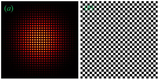
Figure 7.
(a) Intensity distribution and (b) phase of 2D Cosine beam (here, θx = θy = 5°).
2D Cosine beams have non-diffraction and self-healing properties similar to the 1D Cosine beam. These properties are more effective for rectangular objects. The cosine modulations along the x and y directions of the 2D Cosine beam create needle array structures [27] within it. The needle arrays, with their self-healing and non-diffraction properties, could be used for the on-axis trapping of multiple particles in multiple parallel planes simultaneously [28]. The array of needles can be well utilized in parallel guiding of multiple particles [29]. Additionally, these optical needles are well-suitable for interstitial imaging of solid tissues and organs through optical coherence tomography imaging needles [30], and modes can be used in circular dichroism imaging of sparse sub-diffraction objects [31]. The longitudinal axis of the needle array is parallel to the optical axis of the Cosine beam. The intensity and phase of the 2D CG beam produced in the Gaussian host are presented in Figure 7. Here, we used θx = θy = 5° to produce square-shaped needles. We can also generate rectangular needles under the θx ≠ θy condition without any on-axis intensity modulation.
The 2D CG beam can be experimentally realized with SLM or DMD by projecting the phase hologram given in Figure 7b. As we discussed in the 1D Cosine beam, we can also produce complex structures in the 2D Cosine beam by simply changing the host beam.
Intensity Distribution of the 2D Cosine Beam along x, y, and z Coordinates
The intensity distribution of the 2D Cosine beam along the x, y, and z-coordinates is given by Equation (12).
and
The expressions provided in Equation (12) are procured from Figure 1b under 2D Cosine modulations. As we discussed in the preceding section, the z-component of the optical field in a 1D Cosine beam depends on angles ϕ and θ. In whatever way, it is not true in 2D Cosine beams. From Equation (12c), we realize that the longitudinal optical component in a 2D Cosine beam is independent of ϕ, which is attributed to the presence of cross-propagating waves in both xz and yz planes. Anyway, the optical field strength in the transverse components can be well controlled by changing ϕ and θ. From Figure 4 and Figure 7, it is worth noticing that the 1D Cosine beam has cosine modulations in one direction, whereas the 2D Cosine beam has cosine modulations in two orthogonal directions. As a result, the dark region in the 2D Cosine beam is double that of the 1D Cosine beam. Therefore, for fixed angles ϕ and θ = θx = θy, the peak intensity of the Cosine beam is larger in 2D than in 1D. Moreover, the maximum of Iz in a 2D Cosine beam is always less than the corresponding value in a 1D Cosine beam. For example, at θ = 45° and for a peak intensity Io, the max(Iz) = Io/4 in the 2D Cosine beam and max(Iz) = Io/2 in the case of the 1D Cosine beam.
4. Superposition of One-Dimensional Cosine Beams with Same Polarization
The 1D Cosine beam can be understood through the superposition of two plane waves in cross propagation (Section 2). In the same vein, we can understand the superposition of two 1D Cosine beams of |ψx⟩ and |ψy⟩ by the consideration of four-wave interference. Now, let us consider angularly propagating four identical waves emanating from a single laser source. Two waves are in the xz-plane, and the other two are in the yz-plane, i.e., the planes of incidence are orthogonal to each other. Let the four waves be linearly polarized at an angle ϕ with respect to the x-axis. Let the angles created by these waves in the xz-plane and yz-plane with reference to the z-axis be θx and θy, respectively. Then, the state of the k-vector and E-vector for the four waves are present along the directions of x, y, and z coordinates and are given in Table 2. The two vectors have the form of (kx, ky, kz) = (ksinθx, ksinθy, kcosθx + kcosθy) and (Ex, Ey, Ez) = (Ecosϕcosθx, Esinϕcosθy, Ecosϕsinθx + Esinϕsinθy).

Table 2.
The propagation vectors and optical field amplitudes of interfering beams along x, y, and z directions in four-wave interference.
The states of the four waves provided through their propagation parameters are as follows:
and
Here, the three-dimensional polarization states |β⟩ and |β′⟩ of respective waves are the same as given in Equation (2) (detailed expressions can be found in Equation (A2) of Appendix A). The state of superposition can be written in terms of the state of interfering waves as
The intensity distribution of the superposition of two 1D Cosine beams is given by the inner product as
After simple theoretical calculations, we deduce a simple expression for the intensity of the interference as
The full derivation of Equation (16) can be found in Appendix B.
The Intensity of Superposition of One-Dimensional Cosine Beams along x, y, and z Directions
By following the condition of E = E′, the state vector of interference in the x, y, and z directions is given by
and
By the product of Equations (14) and (17), we can obtain the intensities along the x, y, and z directions and are
and
From the above expressions, we can understand that the total intensity, as well as intensities along the x, y, and z directions of interference, depends on angles ϕ, θx, and θy. The optical field component along the z-direction depends on the angles θx and θy in a similar fashion to 1D Cosine beams. For a clear systematic understanding of the interfering intensity distribution, the total intensity of the interference as a result of two 1D Cosine beams is normalized to one. Hence, the fractional optical intensity of each 1D Cosine beam is ½. The calculated fractional intensities of two 1D Cosine beams for ϕ = 0°, 90°, and 45° are given in Table 3. From this table, we can calculate the fractional intensity distribution of the interference pattern along the x, y, and z directions, and corresponding intensity distributions are shown in Figure 8 for θx = θy = 45°. For ϕ = 0°, the 1D Cosine beam in the xz-plane has a cosine intensity distribution along the x-direction for electric field components |ψx⟩ and |ψz⟩ with |ψy⟩ = 0. For the same case, the 1D Cosine beam in the yz-plane has a cosine intensity distribution along the y-direction for electric field component |ψx⟩ with |ψy⟩ = |ψz⟩ = 0. The unequal intensities of the two 1D Cosine beams in the x-direction produce elliptical array spots with its major axis along the x-direction. This effect further produces a mesh shape in the total intensity. A similar effect can also be seen for ϕ = 90°. We can see the effects produced in the interference for ϕ = 0° and ϕ = 90° cases simultaneously with an equal contribution for the consideration of ϕ = 45°. For this condition, the total intensity is in the form of a 2D Cosine beam with its direction in the diagonal. In the present context, the third case is nothing but a superposition of the first two cases. From this, we can conclude that the spatial distributions of intensities I, Ix, Iy, and Iz can be controlled with ϕ, θx, and θy.

Table 3.
Fractional intensities along the x, y, and z directions for θx = θy = 45° for three angles of polarization.
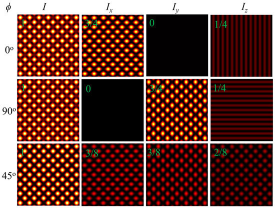
Figure 8.
The transverse intensity distribution of superposed 1D Cosine beams in the xy-plane for ϕ = 0°, 90°, and 45°. Fractional intensities of interference along x, y, and z directions are provided in Green font in the respective images (here, θx = θy = 45°).
In addition to creating different kinds of 2D structures through the superposition of two 1D Cosine beams under the θx = θy condition, we can produce 3D structures by the consideration of θx ≠ θy. In Equation (16), we can perceive that the intensity distribution of the superposition modes depends on z, θx, and θy as cos[kz(cos θx − cos θy)]. From this, we can understand that we can produce periodic changes in the superposition beam along the beam propagation direction with θx ≠ θy. Thus, the superposition of 1D Cosine beams can produce the same structure in regular intervals along the propagation without the aid of any diffractive optical elements, and this property is called the Talbot effect or self-imaging [32,33]. From the nature of self-imaging, we can understand that the superposition of 1D Cosine beams can generate a series of optical needle arrays with due consideration of unequal angles of θx and θy. In Figure 9, we show a series of optical needle arrays for θx-θy = 10°. The unequal θx and θy give rise to an elliptical shape needle, and this ellipticity nature can augment with increasing θx−θy. The tails of the needles overlap with each other along the propagation. The self-healing and non-diffraction nature of optical needles originated from their parent 1D Cosine beams owing to their inherited property. The length of the needles and their visibility decrease with increasing angular difference θx-θy, and this effect can be seen in the line profile plot in Figure 9 along the needle propagation. This is the first report on the demonstration of a series of optical needle arrays. The tunable control over the length and shape of needle arrays, owing to their non-diffraction and self-healing, can enrich their applications in material science. The interference of two 1D Cosine beams can be experimentally realized in a cost-effective way using two orthogonally rotated Fresnel biprisms in tandem within a single laser beam.
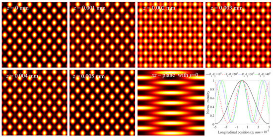
Figure 9.
Optical needle array in series created by two one-dimensional plane wave Cosine beams in the presence of θx − θy = 10°. The first row and first two images of the second row are transverse intensity distributions of the optical needle array at various longitudinal positions. The last two-dimensional image is a longitudinal cross-section of the needle beam in the xz-plane with y = 0. The dependence of periodicity or size of optical needles on θx − θy is shown in the line plot.
5. Superposition of Two Orthogonally Polarized One-Dimensional Cosine–Gauss Beams
Let us consider two pairs of collimated Gaussian beams interfering in cross-propagation with respect to the z-axis. The first pair of beams interfere in the xz-plane with their polarization in the xz-plane to produce a 1D CG beam of |ψx⟩, and the second pair of beams interfere in the yz-plane with their polarization in the yz-plane to create a 1D CG beam of |ψy⟩ in the yz-plane. The resultant superposed state |ψ⟩ in the form of a vector matrix is given by
and horizontal and vertical polarization states are given by
Here, we consider the angle between the beams in the xz-plane (θx) and yz-plane (θy) to be 5° (θx = θy = 5°). Thus, the z component of the electric field can be successfully neglected for our convenience. The intensity and phase distributions of interference are in a mesh shape, as shown in Figure 10a,e. The single polarization state of this 2D Cosine beam can be understood in the presence of a linear polarizer, which is provided by a matrix operator:
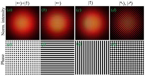
Figure 10.
Generation of various kinds of Cosine–Gauss beams by the superposition of two one-dimensional Cosine–Gauss beams with orthogonal polarization. The first and second rows are the intensity and phase of the Cosine–Gauss beam, respectively, for different states of polarization. Arrows in the ket notation indicate the polarization state of the corresponding Cosine–Gauss beam (here, θx = θy = 5°). The state of superposed beam (a,e) without any polarizer, (b,f) horizontally polarized, (c,g) vertically polarized, and (d,h) polarized at either 45o or 135o.
Here, θp is the angle of the transmission axis of the linear polarizer with reference to the x-axis. In the presence of a polarizer, the transverse intensity and phase of the superposition state can be controlled with its polarization angle, θp. For instance, P(0°) |ψ⟩ = |ψx⟩|←⟩, P(90°) |ψ⟩ = |ψy⟩|↑⟩, and P(45°) |ψ⟩ = |ψx⟩|↗⟩ + |ψy⟩|↗⟩ or P(135°) |ψ⟩ = |ψx⟩|↖⟩ + |ψy⟩|↖⟩ bring out horizontal 1D CG beam, vertical 1D CG beam, and diagonal or anti-diagonal 2D CG beam, respectively. The intensity distributions of diagonal or anti-diagonal 2D CG beams can be further modified by controlling the phase delay between the superposed 1D CG beams or by independently changing the angles, θx and θy. Detailed mathematical expressions for the superposition of two orthogonally polarized 1D Cosine beams are derived in Appendix C.
6. Discussion
To further emphasize the advantage of Cosine beams and illustrations of Dirac notation and ray optics-based analysis for structured beams in fundamental and applied science, we provide some intriguing discussions in this section.
6.1. Bessel Beam in Terms of Cosine Beam
Generally, non-diffracting beams (ex., Bessel beam, Cosine beam, Airy beam, and Bottle beam) are formed by the self-interference produced by mode converters. These beams are considered to be a superposition of n number of plane waves. The Cosine beams are the primary modes of non-diffracting beams. Therefore, we can write these non-diffracting beams in terms of a set of Cosine beams. For instance, below, we provide a brief discussion on the Bessel beam in terms of the Cosine beams.
As we discussed in previous sections, the 1D Cosine beam and 2D Cosine beam are formed as a consequence of the superposition of two and four-plane waves. To create a Bessel beam, we must need an infinite number of plane waves angularly propagating with respect to the z-axis. Eventually, the phase and intensity became the Bessel function instead of the cosine function, as we depicted in Figure 11. Furthermore, the Bessel beam can be generated by the superposition of 1D Cosine beams. It can be proved with the two mathematical expressions below. The Bessel function is equal to the Sinc function [34]:
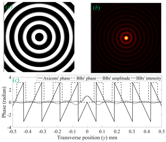
Figure 11.
Properties of Bessel beam generated with an axicon of base angle α = 1° at 640 nm wavelength: (a) phase introduced by the axicon to the incident laser beam for Bessel beam generation, (b) transverse intensity distribution of the Bessel beam, and (c) line profiles of the axicon and Cosine beam (amplitude and intensity of the Cosine beam are normalized to one).
For |r| < 1, the Sinc function can be written in terms of the cosine function as [35]
From the above two expressions, the zeroth-order Bessel function can be written in terms of the cosine function as
Hence, to produce a Bessel beam, we just need a product of an infinite number of 1D Cosine beams. In mathematical analysis, it looks very elusive; however, we can achieve it very easily in experiments through a single axicon.
6.2. Comparative Analysis between Hermite–Gaussian Beam, Cosine Beam, and Bessel Beam
The common property between the HG beam and the Cosine beam is that both beams have separable solutions in x and y. Hence, they can be written as the product of a factor in x and a factor in y. The 1D and 2D cosine modes in the Cosine beam are similar to the 1D and 2D HG modes in the HG beam [4]. Additionally, ideal Bessel and Cosine beams are not square-integrable owing to their infinite energy distribution [3]. However real Bessel and Cosine beams are square-integrable because of their finite size and energy.
In HG beams, non-uniform energy distribution is present with corner lobes having maximum peak intensity. However, an ideal Cosine beam has uniform energy distribution in its cross-section, with all lobes having the same peak intensity. In a similar way, optical energy in all rings of the ideal Bessel beam is equal, but the peak intensity of rings decreases with increasing radius. In the experimental realization of Cosine beams and Bessel beams, the peak intensity and energy in each lob decrease while moving away from the beam axis [28].
Experimentally realized Cosine and Bessel beams are formed as a consequence of interference, and hence, these modes are not Eigenmodes. These modes preserve their shape only for a finite range of propagation. The HG modes are Eigenmodes of the paraxial wave equation and have a stable mode structure throughout their propagation. While the Cosine beam has no mode number, the HG mode has a mode number and is given by N = m + n [4]. Here, m and n are mode orders along the x and y directions. Both the Cosine and HG beams have no helical wavefront. Bessel beam can be quantitatively understood with its mode number l, and it is also called orbital angular momentum. Bessel beams can have a quantized helical wavefront.
While Cosine and Bessel beams have a self-healing and non-diffraction nature, the HG beam does not have these properties. 1D and 2D Cosine beams have non-diffraction and self-healing in rectangular symmetry. Therefore, these properties are effective for rectangular objects whose shape is similar to the lobes in the Cosine beam. The Bessel beam has non-diffraction and self-healing [28] in cylindrical symmetry, and these properties are more effective for circular objects. Both of these beams have these unique properties attributed to the interference of cross-propagating waves along the propagation. Under paraxial propagation, the HG beam has a single propagation vector k = 2π/λ, and it is along its optical axis. However, the 1D Cosine beam has two k vectors, the 2D Cosine beam has four k vectors, and the Bessel beam has an infinite number of k vectors. Their propagation vectors make an angle with the optical axis.
The 1D Cosine beam can have a z-dependent intensity component, Iz, only if it is polarized in the plane of interference. The 2D Cosine beam, Bessel beam, and focused HG beam can always have Iz irrespective of their polarization direction. If the 1D Cosine beam has its polarization in its plane of interference, then the maximum of Iz in the 2D Cosine beam is less than the corresponding value in the 1D Cosine beam. For any arbitrary linear polarization, the z-component of the optical field in the Bessel beam follows the same trend as in the 2D Cosine beam.
As we discussed in Section 4, the interference of 1D Cosine beams can produce a non-diffracting and self-healing series of optical needle arrays. On the other side, the interference of Bessel beams can also generate a non-diffracting and self-healing series of optical bottles and three-dimensional optical potentials [36,37,38].
In addition to scalar modes, we can also generate spatially varying polarization in Cosine beams, Bessel beams, and HG beams. While the polarization changes in the beam cross-section are in radial and azimuthal directions with cylindrical symmetry in the Bessel beams [39,40], in the case of the Cosine beam [41] and HG beam [42], these changes are in Cartesian coordinates with rectangular symmetry.
Ideal Cosine and Bessel beams, formed as a result of plane waves, have constant intensity modulations in their transverse profile with fringe visibility value one. Nevertheless, in a real case, it is not possible to generate a plane wave beam due to its infinite range of energy distribution. Also, depending upon the interfering laser beams’ shape, we can generate different kinds of Cosine and Bessel beams. In real beams, the fringe visibility is spatially variant. The intensity distribution in Cosine beams can be modulated in a controlled manner through the initial polarization and spatial intensity distribution of interfering beams.
6.3. Cosine Beams in Modern Science
As shown in Section 4, we can easily generate a high-power, tunable-size optical needle array at any arbitrary wavelength using 1D Cosine beams through the method of superposition. Compared to previous reports [43,44,45,46], this technique is cost-effective, and it can be well utilized for generating optical needles in any pulsed laser. The weave length of these optical needles can be easily tuned to facilitate them for any application by virtue of nonlinear wave mixing [47]. It is worth noticing that the Talbot length can be further tuned using nonlinear wave mixing without degrading its structure. The observation of the Talbot effect in Cosine beams not only provides a conceptual understanding but also opens the door for a variety of new applications [48]. The Cosine beams and needle structures created from them may be potentially useful in the investigation of nonlinear optical properties of materials [49,50,51]. The 3D optical structures created by the Cosine beams can be utilized in material fabrication to create micro- and nano-structures [52,53,54].
6.4. Feature Scope of Our Analysis
Our method of analysis can be utilized to understand the structural properties of cylindrical-sinc beams [55]. Our analysis can be easily applied to the Bessel beams, and it may simplify the investigation of the polarization effect in material science [56]. The light–matter interaction under singular light field illumination can be studied through our analysis [57]. The susceptibility in nonlinear optics has a tensor form [58,59]. The 3D structure of nonlinear optical susceptibility in a 3D coordinate system can be easily interpreted using the present method of Dirac notation. Any kind of laser beam, irrespective of its initial polarization in the paraxial approximation, has a 3D polarization distribution in the confocal region when it is tightly focused [60,61,62]. In most laser-based applications like material processing and bio-imaging, laser beams need to be tightly focused. The 3D polarization distribution in the confocal region can be easily understood using the method of Dirac representation. It simplifies the understanding of polarization-dependent light–matter interaction. Further, we can extend our analysis to theoretically propose and experimentally demonstrate a Cosine-like beam similar to a Bessel-like beam [63].
7. Conclusions
We successfully demonstrated the origin and characteristics of 1D and 2D non-diffracting beams, whose envelope is a Cosine function, through the Dirac notation and ray optics. Our method of analysis was developed based on obliquely cross-propagating waves to produce a Cosine beam. The superposed waves are in standing waveform and propagating waveform in the respective directions perpendicular and parallel to the optical axis of the Cosine beam. Our method of explanation can be easily applied to any kind of real Cosine beam by considering the necessary apodization function in the theoretical formulation. Further, we have shown that a series of optical needle arrays can be generated by the superposition of two 1D Cosine beams whose propagation direction is the same, but the planes of cosine modulations are orthogonal. The self-healing and non-diffraction nature of the optical needle array generated in Cosine beams augments the quality of optical processes like particle trapping, bio-imaging, material processing, and atomic guiding. Furthermore, the 3D polarization distribution created in the tight-focused vector modes in the confocal region can be easily understood through the present method of demonstration, which is primarily based on Dirac notation.
The similarities between the Cosine beam, Bessel beam, and HG beams are provided with detailed analysis. The proposed method of analysis can have salient features in fundamental and applied optical processes.
Funding
This research received no external funding.
Institutional Review Board Statement
Not applicable.
Informed Consent Statement
Not applicable.
Data Availability Statement
Data are contained within the article.
Conflicts of Interest
The author declares no conflict of interest.
Appendix A. Two-Dimensional Cosine Beam
The second kind Equation of 2D Cosine beam is given by
The expressions for states |βi⟩ and |β′i⟩ are
and
and their product state is given by
and
Here,
and
With consideration of E = E′, we can obtain the following inner products
and
Finally, the 2D Cosine beam inner product is
Appendix B. Interference of Two One-Dimensional Cosine Beams with Their Plane of Incidences Orthogonal to Each Other
The intensity distribution of the superposition of two 1D Cosine beams is given by
Here, the inner product of states |β⟩ and |β′⟩ given by
and
with
The Equation (A8) can be further simplified with Equation (A9a–h) as
Appendix C. Superposition of Orthogonally Polarized Two One-Dimensional Cosine Beams
Equation (A10) can be further simplified for the special cases given below.
Appendix C.1. Linearly Polarized One-Dimensional Cosine Beams with Their Polarization in Their Own Plane of Incident
The state of superposition can be written in terms of interfering beams as
with its three-dimensional polarization states |β⟩ and |β′⟩ have simpler form as
and
and their inner products are given by
and
The intensity distribution in the superposition is given by
with consideration of I = I′,
Appendix C.2. Linearly Polarized One-Dimensional Cosine Beams with Their Polarization Perpendicular to Their Own Plane of Incident
The state of superposition beams is the same as in Appendix C.1, and its polarization states are
and
and their inner products are
and
The intensity distribution in the interference is given by
with consideration of I = I′,
References
- Bandres, M.A.; Gutiérrez-Vega, J.C. Ince–gaussian beams. Opt. Lett. 2004, 29, 144–146. [Google Scholar] [CrossRef]
- Allen, L.; Beijersbergen, M.W.; Spreeuw, R.J.C.; Woerdman, J.P. Orbital angular momentum of light and the transformation of Laguerre-Gaussian laser modes. Phys. Rev. A 1992, 45, 8185. [Google Scholar] [CrossRef]
- Durnin, J. Exact solutions for nondiffracting beams. I. The scalar theory. JOSA A 1987, 4, 651–654. [Google Scholar] [CrossRef]
- Zauderer, E. Complex argument Hermite–Gaussian and Laguerre–Gaussian beams. JOSA A 1986, 3, 465–469. [Google Scholar] [CrossRef]
- Rao, A.S.; Samanta, G.K. On-axis intensity modulation-free, segmented, zero-order Bessel beams with tunable ranges. Opt. Lett. 2018, 43, 3029–3032. [Google Scholar] [CrossRef]
- Berry, M.V.; Balazs, N.L. Nonspreading wave packets. Am. J. Phys. 1979, 47, 264–267. [Google Scholar] [CrossRef]
- Jiang, Z. Truncation of a two-dimensional nondiffracting cos beam. JOSA A 1997, 14, 1478–1481. [Google Scholar] [CrossRef]
- Chaussard, F.; Rigneault, H.; Finot, C. Two-wave interferences space-time duality: Young slits, Fresnel biprism and Billet bilens. Opt. Commun. 2017, 397, 31–38. [Google Scholar] [CrossRef]
- Sabatyan, A.; Hoseini, S.A. Fresnel biprism as a 1D refractive axicon. Optik 2013, 124, 5046–5048. [Google Scholar] [CrossRef]
- Bao, R.; Mou, Z.; Zhou, C.; Bai, Q.; He, X.; Han, Z.; Wang, S.; Teng, S. Generation of diffraction-free beams using resonant metasurfaces. New J. Phys. 2020, 22, 103064. [Google Scholar] [CrossRef]
- Bencheikh, A.; Chabou, S.; Boumeddine, O.C.; Bekkis, H.; Benstiti, A.; Beddiaf, L.; Moussaoui, W. Cosine beam: Diffraction-free propagation and self-healing. JOSA A 2020, 37, C7–C14.s. [Google Scholar] [CrossRef]
- Zhao, D.; Zhang, W.; Wang, S. Propagation characteristics of zero field truncation of COS beam. Opt. Laser Technol. 2001, 33, 523–528. [Google Scholar] [CrossRef]
- Zhao, D.; Shao, R.; Wang, S.; Zhang, W. Propagation of relative phase shift of apertured Cos beams. Optik 2003, 113, 553–555. [Google Scholar] [CrossRef]
- Gu, J.; Zhao, D. Relative phase shift of two-dimensional cosine-Gaussian beams passing through apertured paraxial ABCD optical systems. Optik 2004, 115, 67–70. [Google Scholar] [CrossRef]
- Boubaha, B.; Bencheikh, A.; Aït-Ameur, K. Spatial properties of rectified cosine Gaussian beams. J. Opt. 2014, 16, 025701. [Google Scholar] [CrossRef]
- Wang, S.; Lin, Q.; Lu, X. Realization of super-diffraction limiting propagation by cos beams. Optik 1995, 100, 8–10. [Google Scholar]
- Chang, B.J.; Fiolka, R. Light-sheet engineering using the Field Synthesis theorem. J. Phys. Photonics 2019, 2, 014001. [Google Scholar] [CrossRef]
- Bayraktar, M. Propagation of cosine beam in uniaxial crystal orthogonal to optical axis. Phys. Scr. 2021, 96, 075506. [Google Scholar] [CrossRef]
- Zhang, L.; Li, H.; Liu, Z.; Zhang, J.; Cai, W.; Gao, Y.; Fan, D. Controlling cosine-Gaussian beams in linear media with quadratic external potential. Opt. Exp. 2021, 29, 5128–5140. [Google Scholar] [CrossRef]
- Sun, Z.Y.; Yang, Z.J.; Wang, H.; Pang, Z.G.; Zhang, P.P. Propagation characteristics of cosine-Gaussian cross-phase beams in strongly nonlocal nonlinear media. Optik 2022, 270, 170021. [Google Scholar] [CrossRef]
- Wen, B.; Deng, Y.; Wei, J.; Chen, D.; Leng, X. Evolution of Cos–Gaussian Beams in the Periodic Potential Optical Lattice. Crystals 2022, 12, 1097. [Google Scholar] [CrossRef]
- Shen, J.; Liu, Z.; Liu, J. Expanding non-axisymmetric beams in spherical coordinates with cylindrical wave spectrum decomposition. Results Phys. 2022, 43, 106068. [Google Scholar] [CrossRef]
- Wan-Jun, W.; Zhen-Sen, W. Propagation of annular cos-Gaussian beams through turbulence. J. Opt. Soc. Am. A 2018, 35, 1165–1172. [Google Scholar] [CrossRef]
- Lin, J.; Dellinger, J.; Genevet, P.; Cluzel, B.; de Fornel, F.; Capasso, F. Cosine-Gauss plasmon beam: A localized long-range nondiffracting surface wave. Phys. Rev. Lett. 2012, 109, 093904. [Google Scholar] [CrossRef]
- Hecht, E. Optics, 4th ed.; Pearson Education: San Francisco, CA, USA, 2001; pp. 121–133. [Google Scholar]
- Zettili, N. Quantum Mechanics: Concepts and Applications. 2003. Available online: http://www.mmmut.ac.in/News_content/02110tpnews_11232020.pdf (accessed on 28 November 2023).
- Grunwald, R.; Bock, M. Needle beams: A review. Adv. Phys. X 2020, 5, 1736950. [Google Scholar] [CrossRef]
- McGloin, D.; Dholakia, K. Bessel beams: Diffraction in a new light. Contemp. Phys. 2005, 46, 15–28. [Google Scholar] [CrossRef]
- Tatarkova, S.A.; Sibbett, W.; Dholakia, K. Brownian particle in an optical potential of the washboard type. Phys. Rev. Lett. 2003, 91, 038101. [Google Scholar] [CrossRef]
- Li, X.; Chudoba, C.; Ko, T.; Pitris, C.; Fujimoto, J.G. Imaging needle for optical coherence tomography. Opt. Lett. 2000, 25, 1520–1522. [Google Scholar] [CrossRef]
- Hu, H.; Gan, Q.; Zhan, Q. Generation of a nondiffracting superchiral optical needle for circular dichroism imaging of sparse subdiffraction objects. Phys. Rev. Lett. 2019, 122, 223901. [Google Scholar] [CrossRef]
- Rao, A.S.; Yadav, D.; Samanta, G.K. Nonlinear frequency conversion of 3D optical bottle beams generated using a single axicon. Opt. Lett. 2021, 46, 657–660. [Google Scholar] [CrossRef]
- Hall, L.A.; Yessenov, M.; Ponomarenko, S.A.; Abouraddy, A.F. The space–time Talbot effect. APL Photonics 2021, 6, 056105. [Google Scholar] [CrossRef]
- Abramowitz, M.; Irene, A.S. Handbook of Mathematical Functions with Formulas, Graphs, and Mathematical Tables; US Government Printing Office: Washington, DC, USA, 1948; Volume 55.
- Gradshteyn, I.S.; Ryzhik, M.I. Table of Integrals, Series, and Products; Academic Press: Cambridge, MA, USA, 2014. [Google Scholar]
- Allam, S.R.; Liu, L.; Cai, Y. Generating approximate non-diffractive three dimensional micro-size optical potentials by superposition. Opt. Commun. 2020, 477, 126297. [Google Scholar] [CrossRef]
- Porfirev, A.P.; Skidanov, R.V. Generation of an array of optical bottle beams using a superposition of Bessel beams. Appl. Opt. 2013, 52, 6230–6238. [Google Scholar] [CrossRef]
- McGloin, D.; Spalding, G.C.; Melville, H.; Sibbett, W.; Dholakia, K. Three-dimensional arrays of optical bottle beams. Opt. Commun. 2003, 225, 215–222. [Google Scholar] [CrossRef]
- Otte, E.; Nape, I.; Rosales-Guzmán, C.; Vallés, A.; Denz, C.; Forbes, A. Recovery of nonseparability in self-healing vector Bessel beams. Phys. Rev. A. 2018, 98, 053818. [Google Scholar] [CrossRef]
- Rao, A.S. Illustrations of Bessel Beams in s-Polarization, p-Polarization, Transverse Polarization, and Longitudinal Polarization. Photonics 2023, 10, 1092. [Google Scholar] [CrossRef]
- Piquero, G.; Marcos-Munoz, I.; de Sande, J.C.G. Simple undergraduate experiment for synthesizing and analyzing non-uniformly polarized beams by means of a Fresnel biprism. Am. J. Phys. 2019, 87, 208–213. [Google Scholar] [CrossRef]
- Khonina, S.N.; Porfirev, A.P. Harnessing of inhomogeneously polarized Hermite–Gaussian vector beams to manage the 3D spin angular momentum density distribution. Nanophotonics 2021, 11, 697–712. [Google Scholar] [CrossRef]
- Turquet, L.; Zang, X.; Kakko, J.P.; Lipsanen, H.; Bautista, G.; Kauranen, M. Demonstration of longitudinally polarized optical needles. Opt. Express 2018, 26, 27572–27584. [Google Scholar] [CrossRef]
- Man, Z.; Min, C.; Du, L.; Zhang, Y.; Zhu, S.; Yuan, X. Sub-wavelength sized transversely polarized optical needle with exceptionally suppressed side-lobes. Opt. Express 2016, 24, 874–882. [Google Scholar] [CrossRef]
- Liu, L.; Shi, L.; Li, F.; Yu, S.; Wang, S.; Du, J.; Liu, M.; Qi, B.; Yan, W. Generation of an ultra-long optical needle induced by an azimuthally polarized beam. IEEE Photonics J. 2020, 13, 1–12. [Google Scholar] [CrossRef]
- Rogers, E.T.; Savo, S.; Lindberg, J.; Roy, T.; Dennis, M.R.; Zheludev, N.I. Super-oscillatory optical needle. Appl. Phys. Lett. 2013, 102, 031108. [Google Scholar] [CrossRef]
- Harshith, B.S.; Samanta, G.K. Controlled Generation of Self-images of a Microlens Array and the Second Harmonic Talbot Effect. In ICOL-2019: Proceedings of the International Conference on Optics and Electro-Optics, Dehradun, India; Springer: Singapore, 2021; pp. 85–88. [Google Scholar]
- Wen, J.; Zhang, Y.; Xiao, M. The Talbot effect: Recent advances in classical optics, nonlinear optics, and quantum optics. Adv. Opt. Photonics 2013, 5, 83–130. [Google Scholar] [CrossRef]
- Rosanov, N.N.; Semenov, V.E.; Vyssotina, N.V. Optical needles’ in media with saturating self-focusing nonlinearities. J. Opt. B Quant. Semiclassical Opt. 2001, 3, S96. [Google Scholar] [CrossRef]
- Rao, A.S. Saturation effects in nonlinear absorption, refraction, and frequency conversion: A review. Optik 2022, 267, 169638. [Google Scholar]
- Buono, W.T.; Forbes, A. Nonlinear optics with structured light. Opto-Electron. Adv. 2022, 5, 210174-1. [Google Scholar] [CrossRef]
- Omatsu, T.; Miyamoto, K.; Toyoda, K.; Morita, R.; Arita, Y.; Dholakia, K. A new twist for materials science: The formation of chiral structures using the angular momentum of light. Adv. Opt. Mat. 2019, 7, 1801672. [Google Scholar] [CrossRef]
- Duocastella, M.; Arnold, C.B. Bessel and annular beams for materials processing. Laser Photonics Rev. 2012, 6, 607–621. [Google Scholar] [CrossRef]
- Orlov, S.; Juršėnas, A.; Nacius, E.; Baltrukonis, J. Controllable spatial array of optical needles with independent axial intensity distributions for laser microprocessing. Procedia CIRP 2018, 74, 589–593. [Google Scholar] [CrossRef]
- Bayraktar, M.; Başdemir, H.D. Cylindrical-sinc beam. Optik 2014, 125, 5869–5871. [Google Scholar] [CrossRef]
- Aleksanyan, A.; Brasselet, E. Spin–orbit photonic interaction engineering of Bessel beams. Optica 2016, 3, 167–174. [Google Scholar] [CrossRef]
- Quinteiro, G.F.; Reiter, D.E.; Kuhn, T. Formulation of the twisted-light–matter interaction at the phase singularity: Beams with strong magnetic fields. Phys. Rev. A 2017, 95, 012106. [Google Scholar] [CrossRef]
- Sutherland, R.L. Handbook of Nonlinear Optics, 2nd ed.; CRC Press: Boca Raton, FL, USA, 2003. [Google Scholar]
- Rao, A.S. Overview on Second and Third Order Optical Nonlinear Processes. arXiv 2016, arXiv:1612.09399. [Google Scholar]
- Yu, P.; Zhao, Q.; Hu, X.; Li, Y.; Gong, L. Orbit-induced localized spin angular momentum in the tight focusing of linearly polarized vortex beams. Opt. Lett. 2018, 43, 5677–5680. [Google Scholar] [CrossRef]
- Kovalev, A.A.; Kotlyar, V.V.; Telegin, A.M. Optical Helicity of Light in the Tight Focus. Photonics 2023, 10, 719. [Google Scholar] [CrossRef]
- Khonina, S.N.; Golub, I. Vectorial spin Hall effect of light upon tight focusing. Opt. Lett. 2022, 47, 2166–2169. [Google Scholar] [CrossRef]
- Litvin, I.A.; Mhlanga, T.; Forbes, A. Digital generation of shape-invariant Bessel-like beams. Opt. Exp. 2015, 23, 7312–7319. [Google Scholar] [CrossRef]
Disclaimer/Publisher’s Note: The statements, opinions and data contained in all publications are solely those of the individual author(s) and contributor(s) and not of MDPI and/or the editor(s). MDPI and/or the editor(s) disclaim responsibility for any injury to people or property resulting from any ideas, methods, instructions or products referred to in the content. |
© 2023 by the author. Licensee MDPI, Basel, Switzerland. This article is an open access article distributed under the terms and conditions of the Creative Commons Attribution (CC BY) license (https://creativecommons.org/licenses/by/4.0/).