Generation of a Flat Optical Frequency Comb via a Cascaded Dual-Parallel Mach–Zehnder Modulator and Phase Modulator without Using the Fundamental Tone


Abstract
:1. Introduction
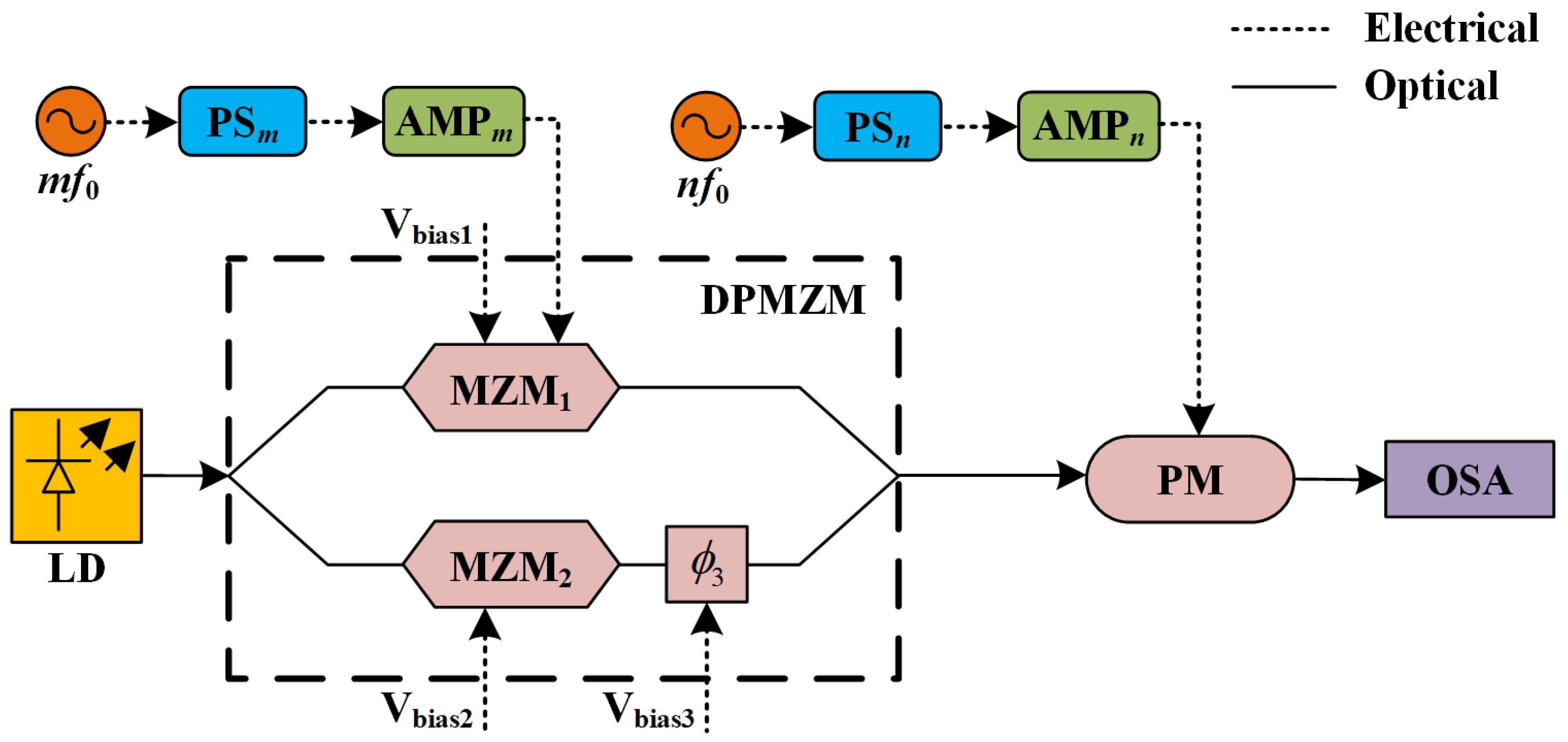
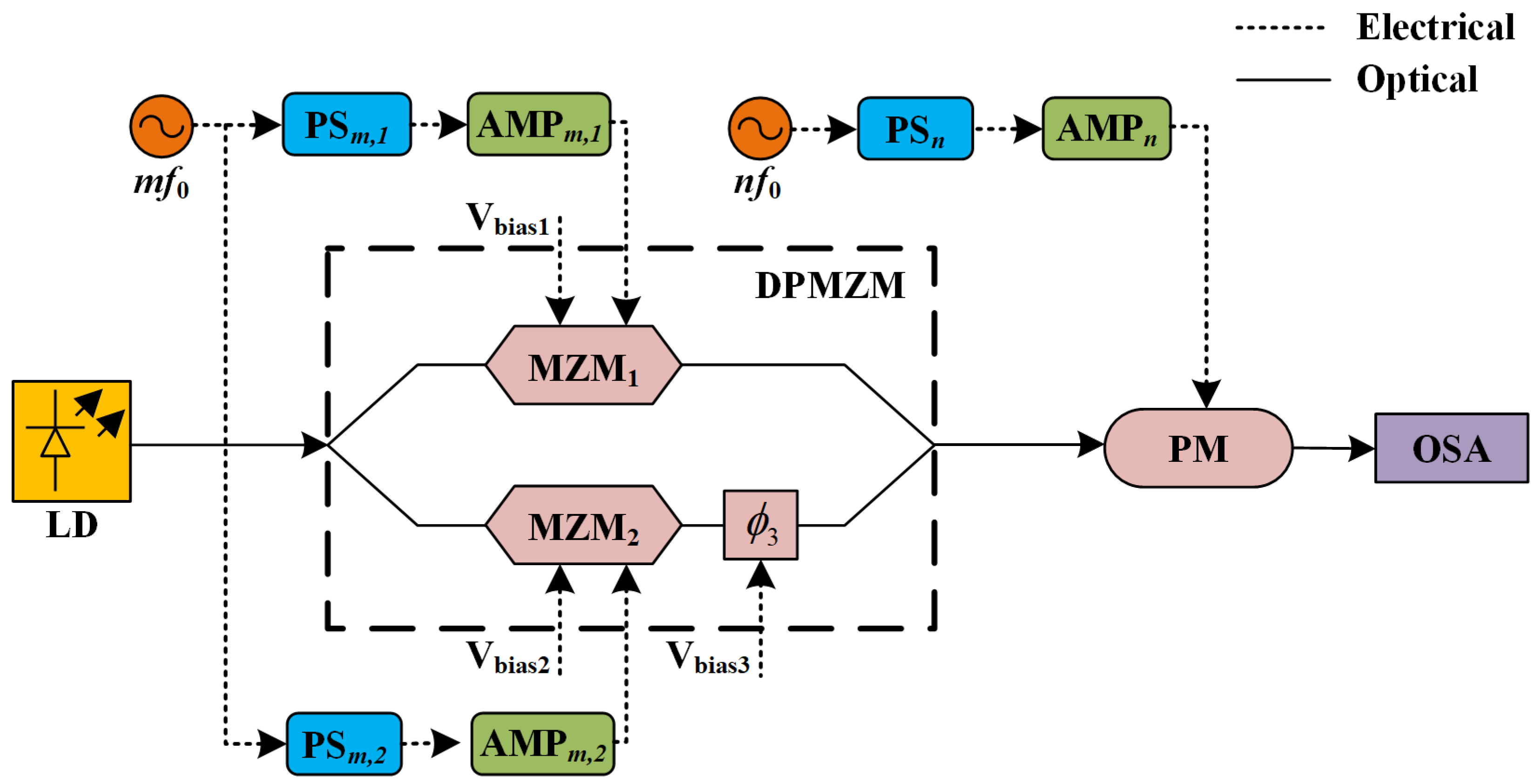
2. Principle
3. Results
3.1. Simulation Results
3.2. Experimental Results
4. Discussion
5. Conclusions
Author Contributions
Funding
Institutional Review Board Statement
Informed Consent Statement
Data Availability Statement
Conflicts of Interest
References
- Kobayashi, T.; Sueta, T.; Cho, Y.; Matsuo, Y. High-repetition-rate optical pulse generator using a Fabry-Perot electro-optic modulator. Appl. Phys. Lett. 1972, 21, 341–343. [Google Scholar] [CrossRef]
- Torres-Company, V.; Weiner, A.M. Optical frequency comb technology for ultra-broadband radio-frequency photonics. Laser Photon. Rev. 2014, 8, 368–393. [Google Scholar] [CrossRef]
- Fujiwara, M.; Teshima, M.; Kani, J.I.; Suzuki, H.; Takachio, N.; Iwatsuki, K. Optical carrier supply module using flattened optical multicarrier generation based on sinusoidal amplitude and phase hybrid modulation. J. Light. Technol. 2003, 21, 2705. [Google Scholar] [CrossRef]
- Wang, J.; Cai, H.; Chen, D.; Qu, R. Generation of ultra-flat optical frequency comb using a balanced driven dual parallel Mach-Zehnder modulator. Chin. Opt. Lett. 2015, 13, 060604. [Google Scholar] [CrossRef]
- Chen, C.; Zhang, F.; Pan, S. Generation of Seven-Line Optical Frequency Comb Based on a Single Polarization Modulator. IEEE Photon. Technol. Lett. 2013, 25, 2164–2166. [Google Scholar] [CrossRef]
- Wu, R.; Supradeepa, V.R.; Long, C.M.; Leaird, D.E.; Weiner, A.M. Generation of very flat optical frequency combs from continuous-wave lasers using cascaded intensity and phase modulators driven by tailored radio frequency waveforms. Opt. Lett. 2010, 35, 3234–3236. [Google Scholar] [CrossRef]
- Lin, T.; Zhao, S.; Zhu, Z.; Li, X.; Qu, K. Generation of Flat Optical Frequency Comb Based on a DP-QPSK Modulator. IEEE Photon. Technol. Lett. 2017, 29, 146–149. [Google Scholar] [CrossRef]
- Tran, T.T.; Song, M.; Song, M.; Seo, D. Highly flat optical frequency comb generation based on pulse carving and sinusoidal phase modulation. Opt. Eng. 2019, 58, 076103. [Google Scholar] [CrossRef]
- Gheorma, I.L.; Gopalakrishnan, G.K. Flat frequency comb generation with an integrated dual-parallel modulator. IEEE Photon. Technol. Lett. 2007, 19, 1011–1013. [Google Scholar] [CrossRef]
- Sakamoto, T.; Kawanishi, T.; Izutsu, M. Asymptotic formalism for ultraflat optical frequency comb generation using a Mach–Zehnder modulator. Opt. Lett. 2007, 32, 1515–1517. [Google Scholar] [CrossRef]
- Sakamoto, T.; Kawanishi, T.; Izutsu, M. Widely wavelength-tunable ultra-flat frequency comb generation using conventional dual-drive Mach–Zehnder modulator. Electron. Lett. 2007, 43, 1. [Google Scholar] [CrossRef]
- Xu, M.; He, M.; Zhu, Y.; Yu, S.; Cai, X. Flat optical frequency comb generator based on integrated lithium niobate modulators. J. Light. Technol. 2022, 40, 339–345. [Google Scholar] [CrossRef]
- Wang, Q.; Huo, L.; Xing, Y.; Zhou, B. Ultra-flat optical frequency comb generator using a single-driven dual-parallel Mach-Zehnder modulator. Opt. Lett. 2014, 39, 3050–3053. [Google Scholar] [CrossRef] [PubMed]
- Shang, L.; Li, Y.; Ma, L.; Chen, J. A flexible and ultra-flat optical frequency comb generator using a parallel Mach-Zehnder modulator with a single DC bias. Opt. Commun. 2015, 356, 70–73. [Google Scholar] [CrossRef]
- Dou, Y.; Zhang, H.; Yao, M. Generation of Flat Optical-Frequency Comb Using Cascaded Intensity and Phase Modulators. IEEE Photon. Technol. Lett. 2012, 24, 727–729. [Google Scholar] [CrossRef]
- Ozharar, S.; Quinlan, F.; Ozdur, I.; Gee, S.; Delfyett, P.J. Ultraflat Optical Comb Generation by Phase-Only Modulation of Continuous-Wave Light. IEEE Photon. Technol. Lett. 2008, 20, 36–38. [Google Scholar] [CrossRef]
- Yan, J.; Zhang, S.; Xia, Z.; Bai, M.; Zheng, Z. A tunable optical frequency comb generator using a single dual parallel Mach-Zehnder modulator. Opt. Laser Technol. 2015, 72, 74–78. [Google Scholar] [CrossRef]
- Yokota, N.; Abe, K.; Mieda, S.; Yasaka, H. Harmonic superposition for tailored optical frequency comb generation by a Mach-Zehnder modulator. Opt. Lett. 2016, 41, 1026–1029. [Google Scholar] [CrossRef]
- Cui, Y.; Wang, Z.; Xu, Y.; Jiang, Y.; Yu, J.; Huang, Z. Generation of Flat Optical Frequency Comb Using Cascaded PMs with Combined Harmonics. IEEE Photon. Technol. Lett. 2022, 34, 490–493. [Google Scholar] [CrossRef]
- Cui, Y.; Wang, Z.; Zuo, X.; Xu, Y.; Jiang, Y.; Yu, J.; Huang, Z. Flat optical frequency comb generation by using one DPMZM and superposed harmonics. Opt. Commun. 2023, 531, 129223. [Google Scholar] [CrossRef]
- Weber, H.J.; Arfken, G.B. Essential Mathematical Methods for Physicists; Elsevier Academic Press: San Diego, CA, USA, 2004. [Google Scholar]
- Feoktistov, V. Differential Evolution—In Search of Solutions; Springer: New York, NY, USA, 2006. [Google Scholar]
- Storn, R.; Price, K. Differential evolution–a simple and efficient heuristic for global optimization over continuous spaces. J. Glob. Optim. 1997, 11, 341–359. [Google Scholar] [CrossRef]


| Case | |||||||
|---|---|---|---|---|---|---|---|
| I | 1.19 | 1.50 | 2.16 | 3.05 | 5.61 | 2.17 | 1.62 |
| II | 1.19 | 1.40 | 2.34 | 3.13 | 5.66 | 4.18 | 3.87 |
| III | 0.99 | 1.43 | 3.45 | 2.40 | 5.78 | 5.19 | 3.42 |
| Scheme | Case I | Case II | Case III | |||
|---|---|---|---|---|---|---|
| Number of Comb Lines | Flatness | Number of Comb Lines | Flatness | Number of Comb Lines | Flatness | |
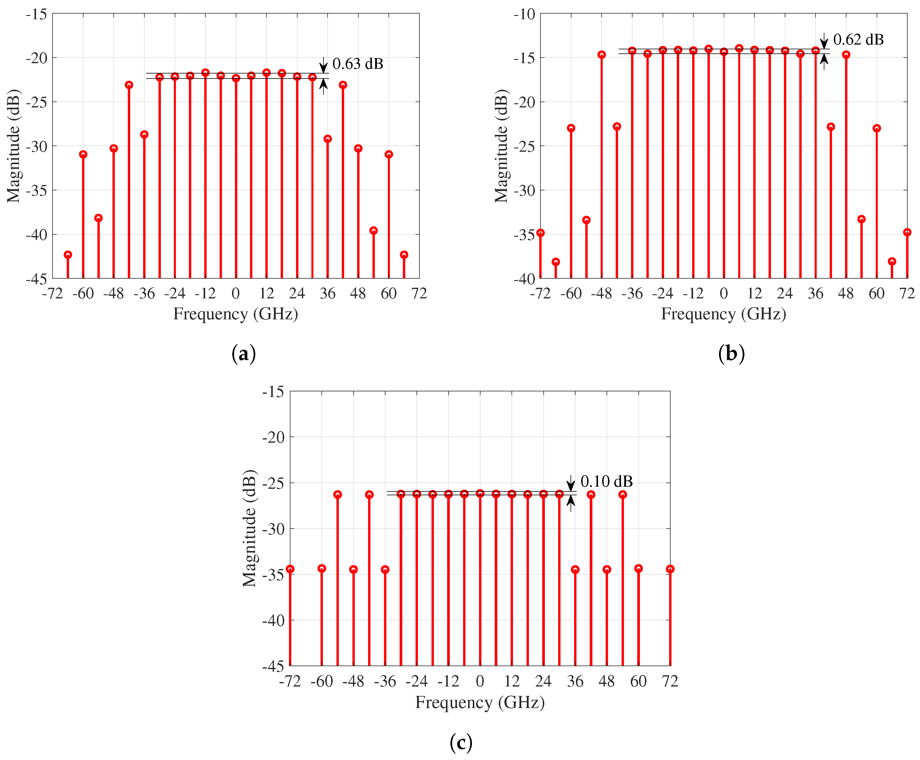
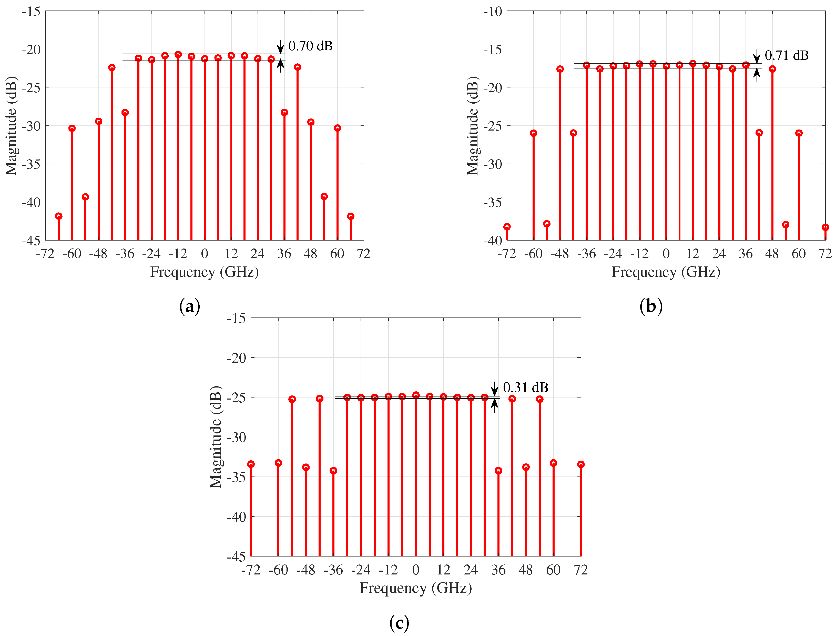
| (1) | 11 | 0.70 dB | 13 | 0.71 dB | 11 | 0.31 dB |
| (2) | 11 | 0.63 dB | 13 | 0.62 dB | 11 | 0.10 dB |
| Improvement by (2) | - | 0.07 dB | - | 0.09 dB | - | 0.21 dB |
| Case | Upper Bound of | Flatness (dB) | Comb Lines | ||
|---|---|---|---|---|---|
| I | 1.5 | 1.19 | 1.50 | 0.63 | 11 |
| 3.0 | 2.17 | 1.54 | 0.26 | 11 | |
| 5.0 | 2.15 | 1.54 | 0.23 | 11 | |
| 7.0 | 2.21 | 1.55 | 0.17 | 11 | |
| 9.0 | 2.04 | 1.53 | 0.20 | 11 | |
| II | 1.5 | 1.19 | 1.40 | 0.62 | 13 |
| 3.0 | 2.44 | 1.39 | 0.49 | 13 | |
| 5.0 | 2.35 | 1.39 | 0.51 | 13 | |
| 7.0 | 2.35 | 1.39 | 0.47 | 13 | |
| 9.0 | 2.77 | 1.39 | 0.33 | 13 | |
| III | 1.5 | 0.99 | 1.43 | 0.10 | 11 |
| 3.0 | 0.83 | 1.42 | 0.14 | 11 | |
| 5.0 | 1.39 | 1.43 | 0.16 | 11 | |
| 7.0 | 1.09 | 1.42 | 0.22 | 11 | |
| 9.0 | 1.15 | 1.42 | 0.23 | 11 |
Disclaimer/Publisher’s Note: The statements, opinions and data contained in all publications are solely those of the individual author(s) and contributor(s) and not of MDPI and/or the editor(s). MDPI and/or the editor(s) disclaim responsibility for any injury to people or property resulting from any ideas, methods, instructions or products referred to in the content. |
© 2023 by the authors. Licensee MDPI, Basel, Switzerland. This article is an open access article distributed under the terms and conditions of the Creative Commons Attribution (CC BY) license (https://creativecommons.org/licenses/by/4.0/).
Share and Cite
Zhang, S.; Wang, Z.; Zuo, X.; Ma, C.; Jiang, Y.; Yu, J. Generation of a Flat Optical Frequency Comb via a Cascaded Dual-Parallel Mach–Zehnder Modulator and Phase Modulator without Using the Fundamental Tone. Photonics 2023, 10, 1340. https://doi.org/10.3390/photonics10121340
Zhang S, Wang Z, Zuo X, Ma C, Jiang Y, Yu J. Generation of a Flat Optical Frequency Comb via a Cascaded Dual-Parallel Mach–Zehnder Modulator and Phase Modulator without Using the Fundamental Tone. Photonics. 2023; 10(12):1340. https://doi.org/10.3390/photonics10121340
Chicago/Turabian StyleZhang, Shiyu, Zixiong Wang, Xunhe Zuo, Chuang Ma, Yang Jiang, and Jinlong Yu. 2023. "Generation of a Flat Optical Frequency Comb via a Cascaded Dual-Parallel Mach–Zehnder Modulator and Phase Modulator without Using the Fundamental Tone" Photonics 10, no. 12: 1340. https://doi.org/10.3390/photonics10121340
APA StyleZhang, S., Wang, Z., Zuo, X., Ma, C., Jiang, Y., & Yu, J. (2023). Generation of a Flat Optical Frequency Comb via a Cascaded Dual-Parallel Mach–Zehnder Modulator and Phase Modulator without Using the Fundamental Tone. Photonics, 10(12), 1340. https://doi.org/10.3390/photonics10121340