Abstract
All-solid-state tunable lasers have been widely used in many fields including multi-photon microscopy, time-resolved photoluminescence, atomic physics, and so on owing to their broadband output spectrum range, good beam quality, and low noise. To cover the broad fluorescent line of the laser crystal as much as possible, a birefringent filter (BRF) is always the most popular candidate for acting as a tuning element. In this review, the tuning characteristics of BRF and the design rule as well as its progress in practical application are summarized. Especially, it is worth noting that laser crystal itself begins to act as the BRF for wavelength tuning except for its gain characteristic, which has paved a new way for developing a kind of novel tunable laser. We believe that this review will not only provide a valuable reference for the design of BRF but also lay the foundation for developing a new application of BRF.
1. Introduction
All-solid-state broadband tunable lasers [1] have been widely used in many fields such as multi-photon microscopy, time-resolved photoluminescence, and so on [2,3,4]. Especially, in the field of atomic physics [5], for the purpose of atom manipulation, it is necessary to match the transition absorption lines of various atoms by continuously scanning the output wavelength of the laser [6,7]. In the field of precision measurement, the broad wavelength tuning range is quite an important characteristic to achieve the different spin-polarized atoms for the highly sensitive measurement of magnetic field and inertia [8]. In the field of quantum simulation, the employed laser source with the continuous frequency-tuning ability acts as the optical tweezer to move atoms to specific position [9]. Generally, the broadband gain media used in tunable lasers always have a wide fluorescence spectrum, such as Ti:sapphire crystal [10], Cr:alexandrite crystal [11], Cr:forsterite [12] and so on, which need to stepwise mode selection to realize wavelength tuning finally. Therefore, the coarse frequency selection has to be firstly attached to the importance and considered. Up to now, there are several ways for coarse frequency selection including the method based on dispersion prism [13], reflected grating [14], and birefringent filter (BRF) [15]. However, BRF is favored by researchers owing to its intrinsic advantage of dispersion-free, broad tuning range, compact body, low loss, and high damage threshold.
Initially, the BRF was first invented by French astronomer Lyot in 1933 [16,17,18,19], which was used for filtering the background light to obtain the desired spectral lines [20]. In order to obtain various spectral lines more efficiently, Billings proposed a method of moving the transmission peak to the desired wavelength by rotating the optic axis of BRF in 1947 [21,22]. Further, in 1949, Evans made attempts to formulate the theory of BRF and described the characteristics of three forms of wide field BRF in detail [23,24]. Especially, the advent of the laser in the 1960s paved the way for the BRF to demonstrate its powerful performance in the tunable lasers [25,26,27,28,29]. In 1974, A. L. Bloom first used the BRF as a laser resonator and reported the characteristic of the BRF with Brewster surface in tunable lasers [30]. Since then, the BRF became the most popular candidate to realize the wavelength tuning of a laser [31,32,33,34,35,36]. At first, the optic axis of the adopted BRF in resonators often lay on the surface of the BRF plate [37,38]. G. Holton et al. employed this kind of BRF for high-power dye lasers and successfully achieved wavelength tuning in a dye laser [39]. At the same time, the BRF has been continuously optimized to meet the requirements, and the theory and application of BRF were extensively covered in the literature [40,41]. In 1976, A. M. Title and S. A. Schoolman reviewed the advances of the BRF since it was invented, which provided a valuable reference for the community [42]. However, with the development of the gain medium with the broadband fluorescent spectrum, the tuning ability of the BRF itself became one of the key limiting factors of laser tuning [43,44,45,46]. In 1985, it was revealed that the BRF with a tilted angle of the optic axis was beneficial to effectively increasing the tuning slope efficiency by comparing the off-axis BRF to that with the optic axis parallel to the surface [47]. In 1988, C. H. Bair et al. achieved the frequency narrowing by using an off-axis BRF with the diving angle of 35 to the surface normal [48]. In 1990, S. Zhu [49] systematically reported the theory and design of the BRF with titled optic axis for tuning dye laser, and summarized that the bandwidth, rejection, and tuning range should be taken into consideration during the BRF design, which supplied a reference to optimize the parameters of BRF including thickness, thickness ratio, and diving angle of optic axis [50,51,52]. In 1992, S. M. Kobtsev et al. [53] summarized the results when the BRF was used for primary narrowing of laser emission spectra, and gave the simple and practical suggestions on the parameters selection of BRF [54,55,56]. To date, based on the theory of BRF, a lot of all-solid-state CW single-frequency tunable lasers have been successfully realized and satisfied the requirements of many fields.
In this review, the research progress of the BRF is systematically introduced, especially summarizing the influences of crucial factors, including tuning angle A, diving angle of the optic axis , thickness of the plate d, on the tuning characteristics of single-plate BRF, and multi-plate BRF. On this basis, many principles of BRF design for tunable lasers are concluded. Meanwhile, the recent progress of the designs and new applications of BRF in the Ti:sapphire laser are reviewed. We believe that all of this work will provide a good reference for designing a suitable BRF for the tunable laser and lay the solid foundation for developing the new application of BRF.
2. Research Progress of BRF Design
2.1. Tuning Characteristics of Single-Plate BRF
In the 1990s, the tunable laser received wide attention for its important application in various fields. In order to exploit the broad gain bandwidth of the laser, high tuning capabilities of the laser had to be taken into account. In general, the BRF is placed in a resonant cavity at the Brewster angle; when the polarization direction of the incident light is parallel to the incident plane (p polarization), it is known that the reflectivity of the incident light on the surface of the crystal is zero, and the polarization direction of the transmitted light is still parallel to the incident plane. Figure 1 is the schematic diagram of a single-plate BRF. perpendicular to the surface of the crystal represents the incident plane, where both incident and refracted rays lie on, and and are the incident and refracted angles, respectively. represents the optic axis and is named the angle between and the BRF surface. Therefore, the projection on the crystal surface is obtained. The angle between and is termed tuning angle A, is the angle between the refractive ray and optic axis. By geometric analysis, the relationship between angle and A can be written by
For the BRF with optic axis on its surface ( = 0), Equation (1) is simplified as
is the angle between the incident plane and the electric displacement vector of refractive light, which can be written as the following equation based on the properties of uniaxial crystals.
For the BRF with optic axis on its surface ( = 0), Equation (3) is simplified as
The transmission of the BRF is expressed as
where is the phase difference in o and e when the polarized light passed through the BRF, d is the thickness of the single-plate BRF.
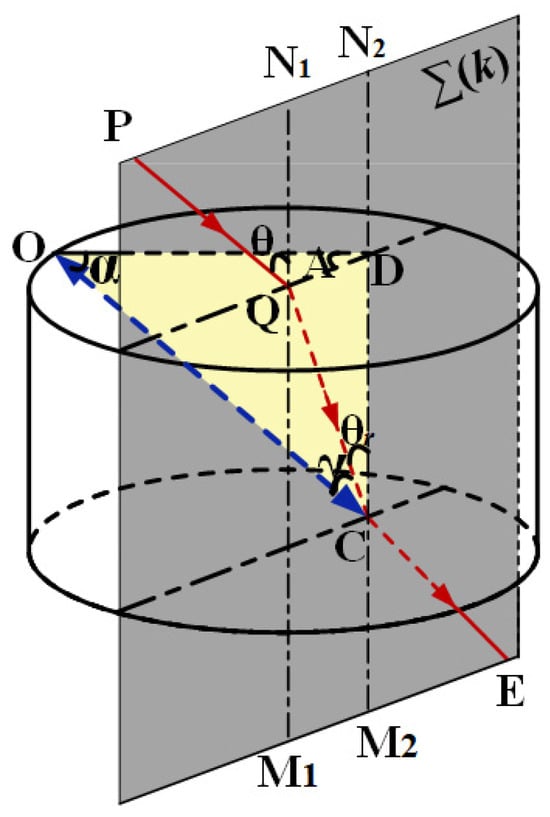
Figure 1.
Schematic diagram of off-axis single-plate BRF.
From Equations (1) and (3), it can be seen that is closely related to and , whereas is related to A and . Therefore, the diving angle of the optic axis and tuning angle A are important factors influenced by T. Additionally, focusing on Equation (5), only if or is equal to zero, T is equal to unity, and the output wavelength loss of zero for transmission of the laser was obtained accordingly. For inevitably leads to T of unity for all wavelengths and does not give rise to frequency selectivity. is the best choice to ensure the wavelength selection ability and the maximum transmission for the output wavelength of the designed BRF. In this case, (k = ±1, ±2, ...). Therefore, the wavelength, which satisfies the following equation
can achieve the maximum transmission when the polarized light passes through the BRF, where is the index difference between o and e rays. m is the interference order. According to the equations above, the tuning characteristics of BRFs with different parameters can be analyzed.
Although the basic theory of BRF has been studied by many researchers, the advantage of off-axis BRF are not well known by the community. One primary reason is that the tuning range of the lasers is restricted by the limited film coating for a long time. Another reason is that for the frequently-used gain medium of the tunable laser, whose fluorescence emission spectrum is relatively narrow [57], researchers are still in the habit of using the on-axis BRF in practical application [58]. In 2007, Ding et al. realized a tunable dual-wavelength output in Ti:sapphire laser with one wavelength range from 700 nm to 756.5 nm, and another from 830 nm to 900 nm by employing a 0.5 mm BRF with the optic axis on its surface [59]. In 2011, Demirbas presented a tunable femtosecond Cr:colquiriite laser, which concluded a quartz BRF with a thickness of 7.3 mm in the cavity [60]. However, with the discovery and wide use of a solid broadband gain medium in all-solid-state tunable lasers [61,62,63], the careful and comprehensive optimization of the BRF becomes a necessary and key work. In 2017, U. Demirbas once presented detailed design considerations of off-axis BRF [64]. They concluded that there were four critical factors that should be taken into account, which were free spectral range (FSR), tuning rate (TR), modulation depth (MD), and walk-off angle (WOA), respectively. According to Equation (5), when neglecting wavelength dispersion of the refractive index n, the FSR can be represented by
The TR represents the tuning slope efficiency of the BRF, which is an important factor that needs to be considered in an ultra-broad tunable laser. It can be expressed as ,
The MD represents the loss for the neighboring wavelengths when the laser resonance is tuned to a specific wavelength, which can be calculated by the following equation.
The WOA is the angle between o and e rays and can be estimated by
where can be obtained by the following equation,
From all of these equations above, it was found that FSR, TR, MD, and WOE were all related to the optic axis diving angle , tuning angle A, and BRF thickness d. Therefore, the principle of BRF design is to make a good balance of FSR, TR, MD, and WOE by selecting reasonable parameters of BRF. Therefore, we will analyze the relationship between them. In addition, it is worth mentioning that all of the following analysis conclusions are obtained in quartz BRF for the BRF made of quartz is a kind of frequency-used and proven frequency selector in actual application. Up to now, the theory above about the BRF design has been widely used in different kinds of tunable laser achievement. For example, E. Beyatlı et al. had successfully achieved widely tunable dual-wavelength operation of Tm:YLF, Tm:LuAG, and Tm:YAG lasers by employing the off-axis BRF in recent year [65]. There were many applications of off-axis BRF in other tunable lasers that we have not listed here. The reader can refer to the literature [66,67,68].
First of all, we investigate the tuning curves of on-axis BRF (). According to Equations (2), (4), and (6), we notice that the tuning curve of BRF is mainly associated with tuning angle A, BRF thickness d, and Brewster Angle . For the quartz BRF, the Brewster Angle is 57.2, and Figure 2 shows the tuning curves of quartz BRF with different thickness d. Here, we only display the wavelength range of 700–1000 nm, which corresponds to the fluorescence range of Ti:sapphire crystal. In the plotted region of Figure 2a, the tuning curve of k = 5 has the broadest wavelength range of 246 nm, the BRF needs to be rotated by 62 to achieve the maximal tuning range without considering the mode-hopping between different interference orders, and the corresponding TR is about 4.0 nm/, which is the same to that of Figure 2b,c. Further, by comparing the tuning curves of BRFs with different thicknesses of 0.5 mm, 1 mm, and 1.5 mm, it is also found that fewer wavelengths can lase depending on the value of A in the plotted range of 700–1000 nm for the thinnest plate, whereas for the thickest plate, lots of wavelengths can lase owing to the dense interference orders. The spacing of the curves represents the FSR of the BRF, so it is found that the FSR is inversely proportional to the thickness of the plate.
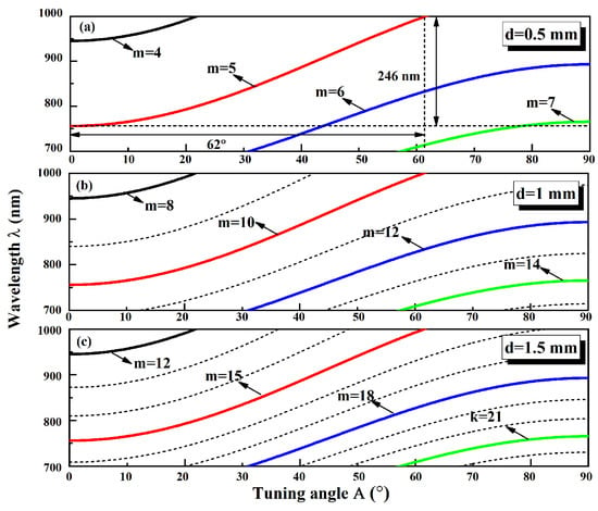
Figure 2.
Tuning curves of BRFs with thickness of (a) 0.5 mm, (b) 1 mm, and (c) 1.5 mm.
Then, the tuning characteristics of the off-axis BRF with different are investigated, which are more complex than that of on-axis BRF. Firstly, according to Equations (1), (3), and (6), the tuning curves of the 0.5 mm BRFs with different diving angles are plotted, which are shown in Figure 3. In order for ease of comparison, the tuning curves of BRF with different diving angles (0∼90) at the same interference orders () are drawn in this figure. Owing to the relationships between the wavelength and tuning angle A being nonlinear, we approximately calculate the TR at different . The TR increases from 8.9 nm/ to 18.5 nm/ when varies from 0 to 40, which is much larger than that of on-axis BRF shown in Figure 2. Just as K. Naganuma claimed, for a specific wavelength region, using the BRF with a steeply diving optic axis, the bandwidth can be changed by a factor of four [69]. When the continuously increases, the TR decreases, and is down to zero when = 90. Meanwhile, we noticed that the tuning slope efficiency achieves the maximum when the diving angle is near 30.
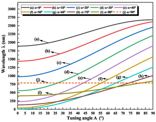
Figure 3.
Tuning curves of BRFs with different values.
Additionally, considering the mode competition, the overlap of tuning curves among different interference orders is undesired, which will be greatly beneficial for smooth wavelength tuning. Therefore, the tuning curves of different interference orders have to be considered. Figure 4 specifically shows the tuning curves of the BRF with diving angles of 30, 35, and 40 when the interference order m is 1, 2, 3, 4, 5, the plotted wavelength range is also 700 nm–1000 nm, which corresponds to the fluorescence range of Ti:sapphire crystal. It is found that the tuning curves of each interference orders have the minimal overlap when = 40, which can give us an important reference for the choice of .
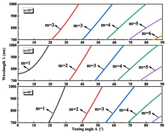
Figure 4.
Tuning curves of BRFs with of 30, 35, and 40.
In order to demonstrate the tuning characteristics of off-axis BRF more intuitively, the FSR at different diving angle when the operating wavelength is 780 nm, which when corresponding to the highest gain of the Ti:sapphire crystal, are firstly calculated according to Equation (7). The results are shown in Figure 5. It is seen that the larger is, the larger FSR is at the same tuning angle A. Meanwhile, we find that the tuning angle A has less effect on FSR when the diving angle is close to zero. With the increase in , the change in FSR increases. Specifically, when the is larger than 40, the change in FSR is very sharp, which reveals that we should avoid choosing the larger than 40.
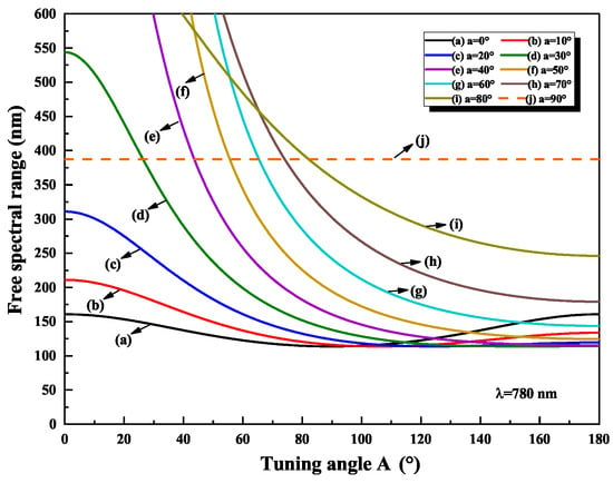
Figure 5.
Free spectral range (FSR) of BRFs with different at operating wavelength of 780 nm.
Next, the MDs are also simulated. According to the definition formula Equation (9) of MD, we desire an MD as large as possible, and want to keep the MD as smooth as possible to obtain good filter rejection across the whole tuning range. In order to explore the variation trend of the MD, the results are divided into three regions, which are plotted in Figure 6. (a) (0 to 57), (b) (58 to 66), and (c) (67 to 90), respectively. It is seen that the MDs are always 0 when the tuning angles are 0 and 180. In Figure 6a,b, the MD becomes asymmetrical and its smooth regions become large with the increase of . Meanwhile, the minimum values of the MD increase when the varies from 58 to 66. When the is near 67, the minimum value of MD is up to 1 and the MD curve has no dip after = 67. As shown in Figure 6c, the variations of MDs are smooth and the maximum value of MD starts to decrease when the increases from 67 to 90. Therefore, we can choose the appropriate according to the above conclusions in practice to achieve the desired tuning results.
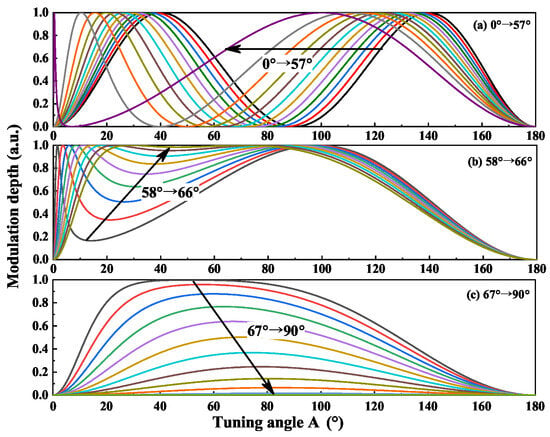
Figure 6.
Modulation depth (MD) of BRFs with different .
In addition, the WOA is another important factor that we need to consider. According to Equations (10) and (11), the WOA is influenced by A and . Figure 7 shows the calculated variation of WOA as a function of A at different diving angle . It is seen that the WOA curve is symmetrical when is 0 , and the WOA is up to the maximum of 0.38 at the tuning angle A of 180, whereas the rest of the WOA values are lower than 0.38, which implies that the WOA can be ignored in practice.
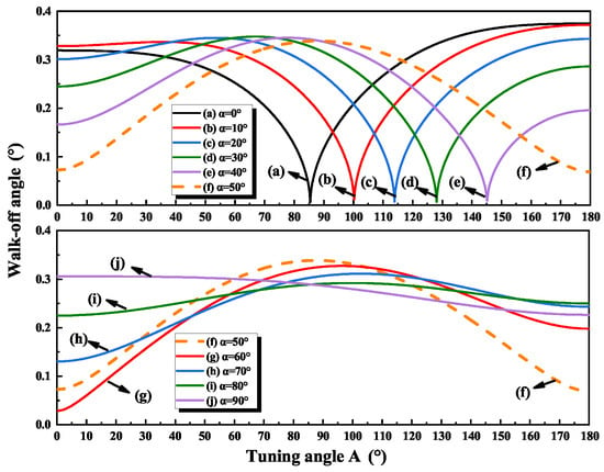
Figure 7.
Walk-off angle (WOA) of BRFs with different .
2.2. Tuning Characteristics of Multi-Plate BRF
The multi-plate BRF is always used to improve the side-mode rejection ability of BRF, in single-frequency continuous-wave wide-band tunable laser. Except for consideration of tuning range covering the fluorescence spectrum of the gain medium, we have to pay more attention to the side-mode rejection. In this section, the influences of thickness ratio on tuning characteristics are analyzed. For the multi-plate BRF, the transmission of the multi-plate BRF can be expressed as
where n is the plate number of the multi-plate BRF, is the phase difference in the ith BRF. Based on this equation, the transmission curves of multi-plate BRFs can be calculated.
For the selection of thickness ratio, by simulating the transmission curves of BRFs with different thickness ratios, a large number of results also can give several suggestions about searching for optimal thickness ratio. The one is that the FSR and linewidth of the multi-plate BRF were determined by the thickness of the thinnest and the thickest plate, respectively. The other one is that the BRFs had better suppression to side-mode when the thickness of the BRFs had no common divisor with each other. In 1992, Wang and Yao once pointed out that the four-plate BRF designed with a thickness ratio of 1:2:4:9 or 1:2:5:9 had maximum blocking from the side transmission peaks [70]. On this basis, we further simulate and compare the transmission curves of 1:2:4:9 and 1:2:5:9 based on Equation (12), and the results are shown in Figure 8. The side-mode transmissions of these two types of multi-plate BRFs are 9.5% and 6.8%, respectively. Clearly, the multi-plate BRF with the thickness ratio of 1:2:5:9 has a higher rejection ability, which verifies the validity of the above conclusions.
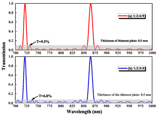
Figure 8.
Transmission curves of multi-plate BRFs ( = 0) with the thickness ratios of 1:2:4:9 and 1:2:5:9.
Then, the transmission curves of multi-plate BRF with different diving angles are calculated, and the results are shown in Figure 9 and Figure 10. It is seen that the side-mode transmission are always lower than 15.1% when the is lower than 30, whereas the transmissions of side-mode increase sharply when the is higher than 30, which is too high to provide enough side-mode rejection for laser frequency selection. Therefore, the lower than 30 is a good candidate in practice. Specifically, Figure 9 marks the FSR and linewidth of the multi-plate BRF at different . It is illustrated that with the increase of , the FSR becomes large, which is beneficial to broadband tuning range achievement, whereas linewidth and side-mode transmission become large, which has an adverse effect on side-mode rejection. Therefore, both tuning range and side-mode rejection should be taken into account and given good balance during the BRF design.
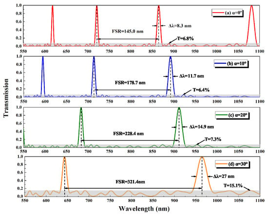
Figure 9.
Transmission curves of BRFs with the thickness ratios of 1:2:5:9 (0∼30).
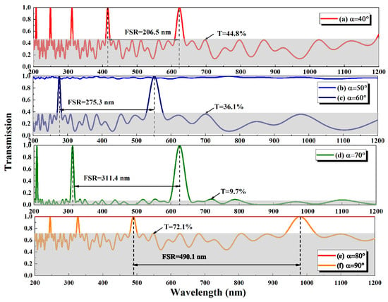
Figure 10.
Transmission curves of the BRFs with thickness ratios of 1:2:5:9 (40∼90).
3. Design of BRF for Single-Frequency Ti:sapphire Tunable Laser
In 2022, our group realized a single-frequency tunable Ti:sapphire laser with a tuning range of 304 nm [71]. In this process, the optimal condition of BRF design was proposed. Based on the proposed optimal condition, we designed an off-axis multi-plate BRF for a single-frequency continuous-wave Ti:sapphire laser. Firstly, focusing on Equation (12), only if or is equal to zero, was equal to unity, and the output wavelength loss of zero for transmission of the laser was obtained accordingly. For , it inevitably led to of unity for all wavelengths and did not give rise to frequency selectivity. was the best choice to ensure the wavelength selection ability and the maximum transmission for the output wavelength of the designed BRF. In this case, (k = ±1, ±2, ...). On contrary, T(, ) was equal to , which represented the minimum transmission of the single-plate BRF.
At first, we investigated the dependency between the tuning characteristics of BRF and diving angle by introducing a parameter D, to represent the ability of side-band rejection, which was similar to MD. D was written by
As shown in Equations (21) and (25), the parameter D was closely related to . Then, the optimal condition of the BRF could be obtained, which was written as
where and were the upper and lower limits for the fluorescence spectrum of the gain crystal, respectively. Clearly, when the gain medium was chosen, the optimal diving angle of the BRF optic axis could be determined. It was worth noting that this proposed optimal condition could be used for the BRF design of all tunable lasers with different emission spectra.
For the Ti:sapphire crystal with the fluorescence spectrum of 700–1000 nm, the relationship between and was simulated and depicted in Figure 11. Clearly, a critical point satisfied the optimal condition in Equation (14), which was termed Q. For point Q, the value of was 29.1, and the value of was closest to the maximum of unity for the wavelength range of 700–1000 nm. Therefore, = 29.1 was determined as the optimal diving angle for the BRF in the wide-band single-frequency continuous-wave tunable Ti:sapphire laser (700–1000 nm). Then, the thinnest plate and thickness ratio of 0.5 mm and 1:2:5:9 were adopted in the experiment to design the broadband tuning element. At last, the tuning curve was measured experimentally by rotating the BRF, which was illustrated along with calculated tuning curves in Figure 12. It was seen that the wavelength of the output laser was successfully tuned from 691 nm to 995 nm (304 nm) with the BRF rotation angle of 19, the corresponding tuning efficiency is 16 nm/. The experimental results were in good agreement with the theoretical analysis results which well demonstrated the reliability of the reported BRF design method.
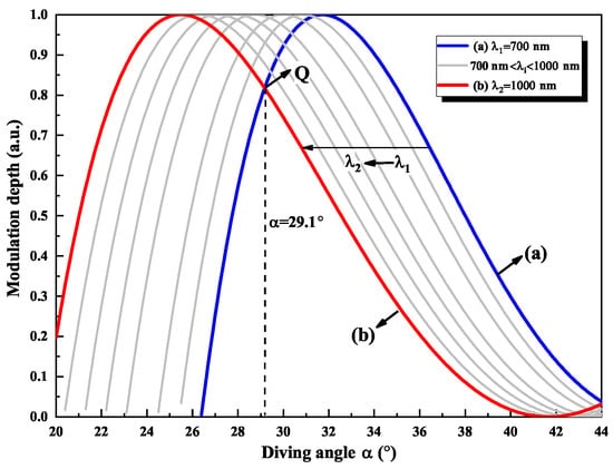
Figure 11.
Relationship between modulation depth (MD) and corresponding to different wavelengths (700 nm–1000 nm).
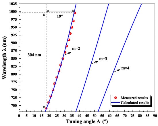
Figure 12.
Measured tuning range of continuous-wave single-frequency Ti:sapphire laser.
After determining the parameters of the BRF and accomplishing the coarse frequency selection, an etalon was directly installed on the spindle of a galvanometer scanner and inserted into the resonator for further fine frequency selection. When the intracavity etalon was successfully locked to the resonant longitudinal mode of the Ti:sapphire laser, the stable single-longitudinal-mode could be observed, and then the continuous frequency tuning was realized.
4. Automatic Control of BRF Used in Single-Frequency Ti:sapphire Tunable Laser
For most wide-band tunable lasers, the wavelength tunings are always realized by manually adjusting the rotation angle of BRF. In 2017, Su et al. designed an automatic and broad tuning procedure based on the control of LabVIEW in continuous-wave single-frequency Ti:sapphire laser, which greatly simplified its operation [72].
The designed experimental setup was shown in Figure 13. It was mentioned that the BRF was mounted on a piezoelectric rotating motor and driven by a piezo controller; the rotation axis of the piezoelectric rotating motor was perpendicular to the surface of the BRF. The angle between the optic axis of BRF and the polarization direction of incident laser could be adjusted continuously by rotating the piezoelectric rotating motor. In order to realize the automatic tuning of the Ti:sapphire laser, the wavelength of the output laser was detected by wavelength meter (WM, WS6/765, High Finesse Laser and Electronic System) with the measuring precision of 0.0001 nm. Meanwhile, the measured real-time wavelength values were read by the LabVIEW program. Then, the read value was compared with the set value, if measured wavelength was far from the set time, the piezoelectric rotating motor would be controlled to rotate until reaching the set value. The process diagram of the LabVIEW program was shown in Figure 14: when starting the program, first read the wavelength value to judge its validity, and if it is invalid, read it again. If it is valid, enter the next wavelength comparison link; if the deviation value is greater than or less than 0.1 nm, the motor is controlled to rotate, and the positive or negative of the deviation value represents the rotation direction.
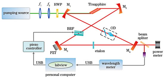
Figure 13.
Schematic of automatically tunable Ti:sapphire laser.
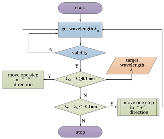
Figure 14.
Flow chart of the feedback control system with the wavelength meter.
The interface of the designed LabVIEW control program was shown in Figure 15a, which was dived into six regions. The measured real-time wavelength was shown in region 1 and region 3, the region 2 was used for wavelength setting, the region 4 shown the wavelength change curve during the tuning process. In region 5, the user could control the rotating motor manually. The region 6 and region 7 was used for assistant control. At last, the output power of different wavelength was measured by using the designed automatic tuning device, and the result was shown in Figure 15b. It was implied that the laser was successfully and automatically tuned from 760 nm to 870 nm by using a multi-plate BRF with the thickness of 1 mm, 2 mm and 4 mm.
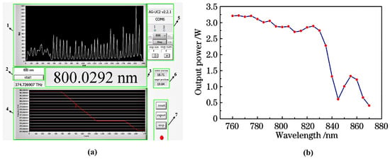
Figure 15.
(a) Interface of the designed LabVIEW control program. (b) Tuning curve of Ti:sapphire laser.
5. New Application of Birefringent Tuning Characteristic
With the rapid progress of science and technology, scientific research is stepping into practice in the 21st century, which proposes requirement for miniaturized lasers, whereas the appearance of anisotropic broadband laser crystals makes it possible to act as a frequency selector, which will have important practical implications, allowing a reduction in size, complexity, and cost with respect to the commonly used tunable lasers. Here, we call it self-tuning crystal (STC). In this process, the structure of the STC also has to be designed carefully. As early as 2003, Fernandez experimentally demonstrated broadband wavelength self-tuning in a KNd(MoO) (KNM) crystal for the first time, providing an effective method for realizing a compact tunable laser [73,74]. In 2005, Iparraguirre et al. realized a self-tuning Ti:sapphire pulsed laser with a tuning range of 120 nm by adopting a single-plate Ti:sapphire crystal [75,76]. Subsequently, they further expanded the tuning range of the self-tuning Ti:sapphire laser by employing a three-plate Ti:sapphire crystal in 2009 [77].
All of the research above was about the STC used in pulsed laser, and the continuous-wave self-tuning laser has not achieved a high pump power threshold. In 2021, J. Wei et al. presented a compact Watt-level single-frequency continuous-wave self-tuning Ti:sapphire laser [78], which was implemented using a three-plate Ti:sapphire crystal with the doping concentration of 0.08 wt.% as both gain medium and frequency-tuning element. The thickness ratio of the three-plate Ti:sapphire crystal was 1:2:4, of which the thinnest plate measured 1 mm. Based on the presented self-tuning crystal, a ring resonator was designed and built, which was shown in Figure 16. The measured maximum wavelength tuning range of the single-frequency self-tuning Ti:sapphire laser was 109 nm, which was shown in Figure 17; the corresponding tuning efficiency was 3.5 nm/. It was worth mentioning that this was the first study to report a single-frequency CW self-tuning Ti:sapphire laser, which provided a feasible approach for achieving a compact all-solid-state single-frequency CW-tunable Ti:sapphire laser. In the future, the tuning range of the tunable self-tuning laser will be further expanded with the optimization of the STC, which depends on the discovery of new STC materials and the continuous improvement of BRF theory.
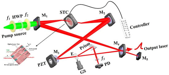
Figure 16.
Experimental setup of designed single-frequency continuous-wave self-tuning Ti:sapphire laser.
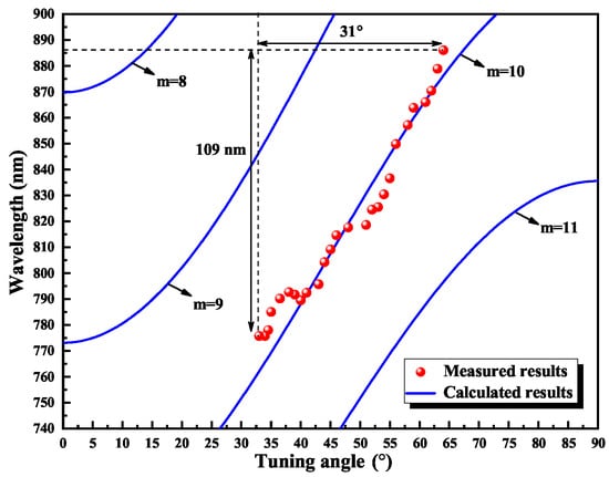
Figure 17.
Measured tuning range of the designed single-frequency continuous-wave self-tuning Ti:sapphire laser.
6. Conclusions
In summary, the BRF is always an important mode-selector and is used in lots of laser resonators. As an excellent mode-selector, its parameters have to be optimized according to the requirements of the laser design. It is obvious that the theory of BRF has become increasingly perfect and systematic with the promotion of higher demands. In this review, the research of single-plate BRF and multi-plate BRF was reviewed. Especially, for the purpose of convenient reference for the community, the influence factors of the BRF tuning characteristics were quantificationally investigated. On this basis, the rules of the BRF design as well as the recent progress of the BRF application were summarized. In particular, many available all-solid-state continuous-wave single-frequency lasers based on the BRF have been successfully demonstrated, which greatly promote the progress of precision measurement, atomic physics, and so on. In the future, as a basic tuning element, the BRF will still play a crucial role in tunable lasers. Furthermore, we firmly believe that tunable lasers will be even smarter with the rapid development of artificial intelligence and machine learning in the future.
Author Contributions
Writing—original draft preparation, J.W.; writing—review and editing, J.S. and H.L.; H.L. provided the insight and useful information; project administration and funding acquisition, K.P. All authors have read and agreed to the published version of the manuscript.
Funding
This research was funded by National Natural Science Foundation of China (62205186; 62027821; 61975100; 62105192), Applied Basic Research Project of Shanxi Province (202203021212478; 202203021212481), Research Project Supported by Shanxi Scholarship Council of China (2022-015), Key R&D Program of Shanxi Province (202102150101002), Applied Basic Research Project of Shanxi Province (202103021221004), Special Fund for Science and Technology Innovation Teams of Shanxi Province (202204051002005), Shanxi Province Patent Conversion Project (202305007), and National Key Research and Development Program of China (2022YFC2204003).
Institutional Review Board Statement
Not applicable.
Informed Consent Statement
Not applicable.
Data Availability Statement
Not applicable.
Conflicts of Interest
The authors declare no conflict of interest.
References
- Sun, Y.; Lu, H.D.; Su, J. Continuous-wave, single-frequency, all-solid-state Ti:Al2O3 laser. Acta Sin. Quantum Opt. 2008, 414, 344. [Google Scholar]
- Xu, Z.X.; Wu, W.Y.; Tian, L.; Chen, L.R.; Zhang, Z.Y.; Yan, Z.H.; Li, S.J.; Wang, H. Long lifetime and high-fidelity quantum memory of photonics polarization qubit by lifting zeeman degeneracy. Phys. Rev. Lett. 2013, 111, 240503. [Google Scholar] [CrossRef]
- Barber, Z.W.; Hoyt, C.W.; Oates, C.W.; Hollberg, L. Direct Excitation of the Forbidden Clock Transition in Neutral 174Yb Atoms Confined to an Optical Lattice. Phys. Rev. Lett. 2006, 96, 083002. [Google Scholar] [CrossRef]
- Wolfgramm, F.; Cere, A.; Beduini, F.A.; Predojevic, A.; Koschorreck, M.; Mitchell, M.W. Squeezed-light optical magnetometry. Phys. Rev. Lett. 2010, 105, 053601. [Google Scholar] [CrossRef]
- Kuwanmoto, T.; Honda, K.; Takahashi, Y.; Yabuzaki, T. Magneto-optical trapping of Yb atoms using an intercombination transition. Phys. Rev. A 1999, 60, R745. [Google Scholar] [CrossRef]
- Wei, K.; Zhao, T.; Fang, X.J.; Zhai, Y.Y.; Li, H.R.; Quan, W. In-situ measurement of the density ratio of K-Rb hybrid vapor cell using spin-exchange collision mixing of the K and Rb light shifts. Opt. Express 2017, 27, 16169. [Google Scholar] [CrossRef]
- Jia, X.J.; Yan, Z.H.; Duan, Z.Y.; Su, X.L.; Wang, H.; Xie, C.D.; Peng, K.C. Experimental Realization of Three-Color Entanglement at Optical Fiber Communication and Atomic Storage Wavelengths. Phys. Rev. Lett. 2012, 109, 253604. [Google Scholar] [CrossRef]
- Gou, Y.; Zhang, Y.D.; Su, H.Y.; Zhu, F.X.; Yi, G.; Wang, J.F. Magnetic-filed tuning whispering gallery mode based on hollow microbubble resonator with Terfenol-D-fixed. Appl. Opt. 2019, 58, 8889. [Google Scholar]
- Wang, Y.B.; Holguin-Lerma, J.A.; Vezzoli, M.; Guo, Y.; Tang, H.X. Photonic-circuit-integrated titanium:sapphire laser. Nat. Photonics 2023, 17, 338. [Google Scholar] [CrossRef]
- Hwang, H.; Byun, A.; Park, J.; de Léséleuc, S.; Ahn, J. Optical tweezers throw and catch single atoms. Optica 2023, 10, 401. [Google Scholar] [CrossRef]
- Kerridge-Johns, W.R.; Damzen, M.J. Analytical model of tunable Alexandrite lasing under diode end-pumping with experimental comparison. J. Opt. Soc. Am. B 2016, 33, 2525. [Google Scholar] [CrossRef]
- Sahoo, S.P.; Pradhan, S.; Mukherjee, J.; Rawat, V.S. Studies of temporal characteristics of all-solid-state, gain-switched Cr:forsterite laser. Optik 2021, 227, 166024. [Google Scholar] [CrossRef]
- Kopylov, D.A.; Esaulkov, M.N.; Kuritsyn, I.I.; Mavritskiy, A.O.; Perminov, B.E.; Konyashchenko, A.V.; Murzina, T.V.; Maydykovskiy, A.I. Kerr-lens mode-locked Ti:Sapphire laser pumped by a single laser diodeU. Laser Phy. Lett. 2018, 15, 045001. [Google Scholar] [CrossRef]
- Pati, B.; Borysow, J. Single-mode tunable Ti:sapphire laser over a wide frequency range. Appl. Opt. 1997, 36, 9337. [Google Scholar] [CrossRef]
- Jin, P.X.; Lu, H.D.; Wei, Y.X.; Su, J.; Peng, K.C. Single-frequency CW Ti:sapphire laser with intensity noise manipulation and continuous frequency-tuning. Opt. Lett. 2017, 42, 143. [Google Scholar] [CrossRef]
- Lyot, B. Quelques observation de la couronne solaire at des protuberances. L’Astronomie 1937, 51, 203. [Google Scholar]
- Lyot, B. The study of the solar corona and prominences without eclipses. Mon. Not. R. Astron. Soc. 1939, 99, 580. [Google Scholar]
- Camichel, H.; Lyot, B. Observations planetaires au pic du midi. L’Astronomie 1941, 57, 49. [Google Scholar]
- Loyt, B. Le filter monochromatique polarisant et ses applications en physique solaire. Ann. D’ Astrophys. 1944, 7, 31. [Google Scholar]
- Lyot, B. Un monochromateur a grand champ utilisant les interferences en Lumiere polarisee. Compt. Rend 1933, 197, 1593. [Google Scholar]
- Billings, B.H.; Hyde, W.L.; Barr, E.E. An investigation of the properties of evaporated metal bolometers. J. Opt. Soc. Am. 1947, 37, 123. [Google Scholar] [CrossRef]
- Billings, B.H.; Land, E.H. A comparative survey of some possible systems of polarized headlights. J. Opt. Soc. Am. 1948, 38, 819. [Google Scholar] [CrossRef]
- Evans, J.W. The birefringent filter. J. Opt. Soc. Am. 1949, 39, 229. [Google Scholar] [CrossRef]
- Šolc, I. Birefringent Chain Filters. J. Opt. Soc. Am. 1965, 55, 621. [Google Scholar] [CrossRef]
- Maiman, T.H. Stimulated emission of radiation in ruby. Nature 1960, 187, 493. [Google Scholar] [CrossRef]
- Sorokin, P.P.; Stevenson, M.J. Stimulated Infrared Emission from Trivalent Uranium. Phys. Rev. Lett. 1960, 5, 557. [Google Scholar] [CrossRef]
- Snitzer, E. Optical maser action of Nd+3 in a Barium Crown Glass. Phys. Rev. Lett. 1961, 7, 444. [Google Scholar] [CrossRef]
- Geusic, J.E.; Marcos, H.M.; Van Uitert, L.G. Laser oscilations in Nd-doped Yttrium Alumnum, Yttrium Gallium and Gadolinium Garnets. Appl. Phys. Lett. 1964, 4, 182. [Google Scholar] [CrossRef]
- Siegman, A.E.; Phillion, D.W.; Kuizenga, D.J. Rotational relaxation and triplet-state effects in the cw dye laser. Appl. Phys. Lett. 1972, 21, 345. [Google Scholar] [CrossRef]
- Bloom, A.L. Modes of a laser resonator containing tilted birefringent plates. J. Opt. Soc. Am. 1974, 64, 447. [Google Scholar] [CrossRef]
- Hodgkinson, I.J.; Vukusic, J.I. Birefringent filters for tuning flashlamp-pumped dye lasers: Simplified theory and design. Appl. Opt. 1978, 17, 1944. [Google Scholar] [CrossRef] [PubMed]
- Title, A.M. Improvement of Birefringent Filters.2: Achromatic Waveplates. Appl. Opt. 1975, 14, 229. [Google Scholar] [CrossRef]
- Hodgkinson, I.J.; Vukusic, J.I. Birefringent tuning filters without secondary peaks. Opt. Commun. 1978, 24, 133. [Google Scholar] [CrossRef]
- Chakraborty, A.K.; Adhikari, B.M. Birefringent Filters. J. Opt. 1977, 6, 73. [Google Scholar] [CrossRef]
- Yano, T.; Watanabe, A. New noncollinear acousto-optic tunable filter using birefringence in paratellurite. Appl. Phys. Lett. 1974, 24, 256. [Google Scholar] [CrossRef]
- Tang, C.L.; Kreismanis, V.G.; Ballantyne, J.M. Wide-band electro-optical tuning of semiconductor lasers. Appl. Phys. Lett. 1977, 30, 113. [Google Scholar] [CrossRef]
- Preuss, D.R.; Gole, J.L. Three-stage birefringent filter tuning smoothly over the visible region: Theoretical treatment and experimental design. Appl. Opt. 1980, 19, 702. [Google Scholar] [CrossRef]
- Liu, Y.S. Line narrowing and tuning of high-power Nd:glass laser using an an intracavity Brewster-angle birefringent filter. J. Appl. Phys. 1977, 48, 647. [Google Scholar] [CrossRef]
- Holtom, G.; Teschke, O. Design of a Birefringent Filter for High-power dye lasers. IEEE J. Quantum Electron. 1974, 10, 577. [Google Scholar] [CrossRef]
- Kachanow, A.A. Birefringent selector of the emission wavelength for a CW dye laser. Sov. J. Quantum Electron. 1982, 12, 927. [Google Scholar] [CrossRef]
- Mental, J.; Schmidt, E.; Mavrudis, T. Birefringent filter with arbitrary orientation of the optic axis: An analysis of improved accuracy. Appl. Opt. 1992, 31, 5022. [Google Scholar] [CrossRef] [PubMed]
- Title, A.M.; Schoolman, S.A. Recent advances in birefringent filters. Polariz. Light 1976, 88, 23. [Google Scholar]
- Kuhl, J.; Lambrich, R.; Linde, D.V. Generation of near-infrared picosecond pulses by mode-locked synchronous pumping of a jet-stream dye laser. Appl. Phys. Lett. 1977, 31, 657. [Google Scholar] [CrossRef]
- Kuhl, J.; Telle, H.; Schieder, R.; Brinkmann, U. New efficient and stable laser dyes for cw operation in the blue and violet spectral region. Opt. Commun. 1978, 24, 251. [Google Scholar] [CrossRef]
- Moulton, P.F.; Mooradian, A. Broadly tunable CW operation of Ni:MgF2 and Co:MgF2 lasers. Appl. Phys. Lett. 1979, 35, 838. [Google Scholar] [CrossRef]
- Moulton, P.F. Pulsed-pumped operation of divalent transition-metal lasers. IEEE J. Quantum Electron. 1982, 18, 1185. [Google Scholar] [CrossRef]
- Lovold, S.; Moulton, P.F.; Killinger, D.K.; Menyuk, N. Frequency tuning characteristics of a Q-Switched Co:MgF2 laser. IEEE J. Quantum Electron. 1985, 21, 202. [Google Scholar] [CrossRef]
- Bair, C.H.; Brockman, P.; Hess, R.V.; Modlin, E.A. Demonstration of frequency control and CW diode laser injection control of a Titanium-doped sapphire ring laser with no internal optical elements. IEEE J. Quantum Electron. 1988, 24, 1045. [Google Scholar] [CrossRef]
- Zhu, S.D. Birefringent filter with tilted optic axis for tuning dye lasers: Theory and design. Appl. Opt. 1990, 29, 410. [Google Scholar] [CrossRef]
- Demirbas, U.; Thesinga, J.; Beyatli, E.; Kellert, M.; Pergament, M.; Kartner, F.X. Continuous-wave Tm:YLF laser with ultrabroad tuning (1772–2145 nm). Opt. Express 2022, 30, 41219. [Google Scholar] [CrossRef]
- Lai, W.Y.; Zhang, H.; Zhu, Z.X.; Yan, P.G.; Ruan, S.C.; Sun, Z.P.; Wang, J.Z. Sub-200 fs, 344MHz mode-locked Tm-doped fiber laser. Opt. Lett. 2020, 45, 5492. [Google Scholar] [CrossRef] [PubMed]
- Nadimi, M.; Major, A. Continuous-wave dual-wavelength operation of a diode-pumped Nd:GdVO4 laser at the 1063&1071 nm, 1063&1083 nm and 1083&1086 nm wavelength pairs. Laser Phys. 2018, 28, 095001. [Google Scholar]
- Kobtsev, S.M.; Sventsitskaya, N.A. Application of birefringent filters in continuous-wave tunable lasers: A review. Opt. Spectrosc. 1992, 73, 114. [Google Scholar]
- Demirbas, U. Cr:Colquiriite Lasers: Current status and challenges for further progress. Prog. Quantum Electron. 2019, 68, 100227. [Google Scholar] [CrossRef]
- Erturk, Z.; Okuyucu, S.; Kilinc, M.; Ozturk, Y.; Pergament, M.; Kärtner, F.X.; Demirbas, U. Broadly tunable two-color lasing of Cr:LiCAF with on-surface and off-surface optical axis birefringent filters: Performance comparison. Appl. Opt. 2022, 61, 10735. [Google Scholar] [CrossRef]
- Xue, Y.C.; Dai, Z.D.; Cao, W.H.; Wang, Z.Y.; Xiao, B.; Xu, H.; Cai, Z. Watt-Level Pr3+:LiYF4 Novel Green Lasers at 519 nm, 538 nm, and 550 nm. IEEE J. Quantum Electron. 2023, 59, 1700305. [Google Scholar] [CrossRef]
- Johnston, T.F.; Brady, R.H.; Proffitt, W. Supercontinua for high-resolution absorption multiplex infrared spectroscopy. Appl. Opt. 1982, 21, 2307. [Google Scholar] [CrossRef]
- Wei, Y.X.; Lu, H.D.; Jin, P.X.; Peng, K.C. Self-injection locked CW single-frequency tunable Ti:sapphire laser. Opt. Express 2017, 25, 21379. [Google Scholar] [CrossRef]
- Ding, X.; Ma, H.M.; Zou, L.; Zou, Y.; Wen, W.Q.; Wang, P.; Yao, J.Q. An all-solid-state high power quasi-continuous-wave tunable dual-wavelength Ti:sapphire laser system using birefringence filter. Chin. Phys. 2007, 16, 1991. [Google Scholar]
- Demirbas, U.; Petrich, G.S.; Li, D.; Sennaroglu, A.; Kolodziejski, L.A.; Kartner, F.X.; Fujimoto, J.G. Femtosecond tuning of Cr:colquiriite lasers with AlGaAs-based saturable Bragg reflectors. J. Opt. Soc. Am. B 2011, 28, 986. [Google Scholar] [CrossRef]
- Walling, J.; Peterson, O.; Morris, R. Tunable CW Alexandrite laser. IEEE J. Quantum. Electron. 1980, 16, 120. [Google Scholar] [CrossRef]
- Tawy, G.; Minassian, A.; Damzen, M.J. High-power 7.4W TEM00 and wavelength-tunable alexandrite laser with a novel cavity design and efficient fibre-coupled diode-pumping. OSA Contin. 2020, 3, 1638. [Google Scholar] [CrossRef]
- Dodge, M.J. Refractive properties of magnesium fluoride. Appl. Opt. 1984, 23, 1980. [Google Scholar] [CrossRef] [PubMed]
- Demirbas, U. Off-surface optic axis birefringent filters for smooth tuning of broadband lasers. Appl. Opt. 2017, 56, 7815. [Google Scholar] [CrossRef] [PubMed]
- Beyatl, E.; Demırbas, U. Widely tunable dual-wavelength operation of Tm:YLF, Tm:LuAG, and Tm:YAG lasers using off-surface optic axis birefringent filters. Appl. Opt. 2018, 57, 6679. [Google Scholar] [CrossRef]
- Demirbas, U.; Cankaya, H.; Thesinga, J.; Kärtner, F.X.; Pergament, M. Efficient, diode-pumped, high-power (>300W) cryogenic Yb:YLF laser with broad-tunability (995–1020.5 nm): Investigation of E//a-axis for lasing. Opt. Express 2019, 27, 36562. [Google Scholar] [CrossRef]
- Demirbas, U.; Kärtner, F.X.; Pergament, M. Cavity-dumped nanosecond Cr:LiSAF laser in the 985–1030 nm region for versatile seeding of Yb-based amplifiers. Appl. Phys. B 2022, 128, 20. [Google Scholar] [CrossRef]
- Mekteplioglu, M.F.; Ozturk, Y.; Pergament, M. Broadly tunable (402–535 nm) intracavity frequency-doubled Cr:LiSAF laser. Appl. Phys. B 2023, 129, 22. [Google Scholar] [CrossRef]
- Naganuma, K.; Lenz, G. Variable bandwidth birefringent filter for tunable femtosecond lasers. IEEE J. Quantum Electron. 1992, 28, 2142. [Google Scholar] [CrossRef]
- Wang, X.L.; Yao, J.Q. Transmitted and tuning characteristics of birefringent filters. Appl. Opt. 1992, 31, 4505. [Google Scholar] [CrossRef]
- Wei, J.; Cao, X.C.; Jin, P.X.; Su, J.; Lu, H.D.; Peng, K.C. Diving angle optimization of BRF in a single-frequency continuous-wave wideband tunable titanium:sapphire laser. Opt. Express 2021, 29, 6714. [Google Scholar] [CrossRef]
- Su, J.; Jin, P.X.; Wei, Y.X.; Lu, H.D.; Peng, K.C. Automatically and broadly tunable all-solid-state continuous single-frequency Ti:sapphire laser. Chin. J. Lasers 2017, 44, 0701006. [Google Scholar]
- Fernandez, J.; Iparraguirre, I.; Aramburu, I.; Illarramendi, A.; Azkargorta, J.; Voda, M. K5Nd(MoO4)4: A self-tunable laser crystal. Opt. Lett. 2003, 28, 1341. [Google Scholar] [CrossRef]
- Fernandez, J.; Illarramendi, M.A.; Iparraguirre, I.; Aramburu, I.; Azkargorta, J.; Voda, M.; Al-Saleh, M.; Balda, R. Rb5Nd(MoO4)4 a self-tunable birefringent laser crystal. Opt. Mater. 2004, 26, 483. [Google Scholar] [CrossRef]
- Aramburu, I.; Iparraguirre, I.; Illarramendi, M.A.; Azkargorta, J.; Fernandez, J.; Balda, R. Self-tuning in birefringent La3Ga5SiO14:Nd3+ laser crystal. Opt. Mater. 2005, 27, 1692. [Google Scholar] [CrossRef]
- Iparraguirre, I.; Aramburu, I.; Azkargorta, J.; Illarramendi, M.A.; Fernandez, J.; Balda, R. Wavelength tuning of Titanium Sapphire Laser by its own crystal birefringence. Opt. Express 2005, 13, 1254. [Google Scholar] [CrossRef] [PubMed]
- Iparraguirre, I.; Azkargorta, J.; Fernandez, J.; Balda, R.; Gatelurrutia, T.; Illarramendi, M.A.; Aramburu, I. A self-tunable Titanium Sapphire Laser by rotating a set of parallel plates of active material. Opt. Express 2009, 17, 3771. [Google Scholar] [CrossRef]
- Wei, J.; Cao, X.C.; Jin, P.X.; Shi, Z.; Su, J.; Lu, H.D. Realization of compact Watt-level single-frequency continuous-wave self-tuning titanium: Sapphire laser. Opt. Express 2021, 29, 2679. [Google Scholar] [CrossRef]
Disclaimer/Publisher’s Note: The statements, opinions and data contained in all publications are solely those of the individual author(s) and contributor(s) and not of MDPI and/or the editor(s). MDPI and/or the editor(s) disclaim responsibility for any injury to people or property resulting from any ideas, methods, instructions or products referred to in the content. |
© 2023 by the authors. Licensee MDPI, Basel, Switzerland. This article is an open access article distributed under the terms and conditions of the Creative Commons Attribution (CC BY) license (https://creativecommons.org/licenses/by/4.0/).