Abstract
Piezoelectric fast steering mirror (PZT FSM) is the core component of the fine tracking system for space laser communication, and its actuator is a piezoelectric ceramic. Consequently, there is a hysteretic nonlinear disturbance throughout the entire range of the FSM’s steering. To enhance the fine tracking system’s performance, this paper innovatively analyzes and verifies the effect of the PZT FSM hysteresis characteristics on the error suppression bandwidth of the fine tracking system. Firstly, the rate-dependent hysteresis model is established by serially connecting the Prandtl–Ishlinskii (P-I) model with the dynamic linear mode. The inverse model is designed as a feedforward controller, followed by the conduction of open-loop feedforward compensation experiments. Subsequently, we propose a compound control method based on the rate-dependent hysteresis mode and conduct a simulation analysis. Finally, the experimental platform for the fine tracking system is set up, and the optimization effect of compensating for hysteresis nonlinearity on the fine tracking system is verified. The experimental results show that the nonlinearity of the PZT FSM is improved by 30% in the middle- and high-frequency ranges, and the error suppression bandwidth of the fine tracking system is improved by 41.7%. This effectively enhances the fine tracking system’s error suppression capability.
1. Introduction
Currently, the demand for satellite observation data is on the rise, and satellite networking is being widely discussed. Traditional satellite communication methods are constrained in terms of device size, weight, volume, and communication rate, and the radio spectrum is becoming more congested due to the increasing number of satellite launches. As a result, space laser communication is considered an effective solution for satellite communication [1,2,3]. For example, SpaceX’s Starlink project is a satellite Internet service that aims to provide high-speed Internet connectivity worldwide by deploying a large network of satellites. In September 2021, the Starlink project was launched from Vandenberg Space Force Base in California aboard a Falcon 9 rocket. It carried Internet satellites equipped with laser links for satellite communications into orbit. The Tokyo University of Aeronautics and Astronautics also proposed the concept and conducted research on laser communication between a 100 kg low-earth-orbit (LEO) satellite and a geostationary-earth-orbit (GEO) satellite. They demonstrated the feasibility of transmission from a 100 kg LEO satellite to a GEO satellite through link budget analysis [4]. Therefore, laser communication is a highly researched topic in the field of satellite communications.
To ensure the stability of the laser communication link, it is necessary to accurately align the beams of the two communicating sides. The required alignment accuracy is typically in the order of μrad. Laser communication usually employs a compound-axis tracking system, which combines a coarse tracking system and a fine tracking system to meet the accuracy requirements. The coarse tracking system is based on a servo turntable and possesses characteristics of a wide dynamic range; it primarily suppresses the disturbance of low frequency and high amplitude of the beam. The fine tracking system is based on an FSM and exhibits fast response characteristics. It is primarily used to compensate for the residual errors of the coarse tracking system and to suppress disturbances in the middle- and high-frequency ranges. The higher the bandwidth of the fine tracking control system, the better the dynamic target tracking ability and the stronger the stability of the compound-axis system. It has been proven that in order to fully take advantage of the compound-axis system, the closed-loop bandwidth of the fine tracking system should be six to ten times the closed-loop bandwidth of the coarse tracking system, or even higher [5]. Therefore, improving the bandwidth of the fine tracking system is beneficial for enhancing the overall dynamic performance of the compound-axis system. PZT FSM is the core component of the fine tracking system, possessing a high resonant frequency and excellent dynamic performance. Consequently, PZT FSM is also widely used in other dynamic target tracking fields. However, the piezoelectric actuator of PZT FSM exhibits nonlinear characteristics such as hysteresis, which can constrain its performance. Therefore, this paper primarily focuses on studying hysteresis compensation for PZT FSM and its impact on improving the bandwidth of the fine tracking control system.
1.1. Research Status
Currently, the research on PZT FSM is primarily divided into two aspects. One of the aspects involves modeling the hysteresis characteristics of PZT FSM and intelligently identifying the model parameters. The other aspect focuses on studying the control methods. The typical control methods include feedforward control, feedback control, and compound control combining feedforward and feedback.
1.1.1. Hysteresis Modeling
Piezoelectric actuators have several advantages, including their small size, light weight, strong driving force, low noise, nanometer-level resolution, ultra-high repeatable positioning accuracy, and excellent dynamic characteristics. As a result, they find wide application in fields such as precision manufacturing [6], biomedicine [7], ultra-precision micro- and nano-processing [8,9], aerospace [10], robotics [11], and precision optics [12]. PZT FSM offers advantages such as fast response speed, high pointing accuracy, a high resonant frequency, and strong resistance to electromagnetic interference. As a result, it finds wide application in systems such as laser communication [13,14], adaptive optics [15], laser beam machining [16], and three-dimensional microscopy [17].
The hysteresis characteristics of piezoelectric actuators make their inputs and outputs nonlinear. This nonlinearity increases with the frequency of the input signal. This characteristic, known as rate dependency, can impact the closed-loop control performance of the fine tracking system [18,19,20,21]. The traditional approach involves adding a closed-loop control within the piezoelectric actuator to achieve linearization. However, this can significantly reduce the bandwidth of the fine tracking system. Researchers have recently proposed numerous hysteresis models for piezoelectric actuators. These models primarily include the Preisach model [22,23,24], the Prandtl–Ishlinskii (P-I) model [25], the Krasonselskii–Pokrovskii (K-P) model [26], and the Bouc–Wen (B-W) model [27]. However, the models mentioned above are static models, and their accuracy tends to decrease as the input signal frequency increases. Therefore, researchers have explored the relationship between input signal frequency and hysteresis characteristics, and propose a rate-dependent hysteresis model based on a Hammerstein structure [28].
The models mentioned above can describe hysteresis characteristics effectively. However, for the fine tracking control system, the P-I model is a more suitable choice due to its fast calculation speed and simple structure. Consequently, the rate-dependent hysteresis model of PZT FSM is established using a Hammerstein structure composed of a P-I model and a dynamic linear mode.
1.1.2. Control Methods
In recent years, there have been some studies on PZT FSM control methods. In [29], the author adopts the feedback control method of a double-proportional-integral-derivative (PID) closed loop, which reduces the tracking error by 46% compared to single-PID control when using a tracking signal with a frequency of 30 Hz. However, since this method improves hysteresis nonlinearity through the internal closed loop, it also reduces the response speed and bandwidth of the system. In [30], the author adopts the Smith pre-estimation method combined with the PID control method. When compared with traditional PID control, the system’s error suppression bandwidth improves by 26%. However, since hysteretic nonlinear disturbance was not considered in this paper, the dynamic performance of the system could be further enhanced. In [31], the author proposes a robust adaptive control method that treats hysteretic nonlinearity as an external disturbance. This control method exhibits strong robustness in the presence of uncertain system parameters. However, it may not be well suited for the fine tracking control system, which has rapidly changing input signals.
In fact, feedforward compensation based on a rate-dependent hysteresis model is an effective method for enhancing the performance of PZT FSM. However, according to the current research status, few researchers have examined the impact of this method on the bandwidth of a closed-loop tracking system. In satellite laser communication, factors such as micro-meteorite impacts, Earth and Moon gravity, external temperature changes, and other influences can lead to vibrations in the satellite platform. These vibrations can result in communication link instability and a reduction in communication rates. The OLYMPUS satellite, launched by the European Space Agency, tested the frequency range of satellite vibrations mainly from 1 Hz to 200 Hz, with the disturbance frequency range of greater impact being around 1 to 100 Hz [32]. Thus, in the laser communication fine tracking control system, the suppression bandwidth of system errors stands as a crucial performance index. Improving the error suppression bandwidth has been proven to be an effective method for enhancing the communication rate.
1.2. Main Contributions
In this paper, we set up an experimental platform for the fine tracking system, verify the accuracy of the rate-dependent hysteresis model, and analyze the advantages of the compound control method based on the rate-dependent hysteresis model. Finally, we test the effectiveness of this control method in improving the error suppression bandwidth of the fine tracking system.
2. Materials and Methods
2.1. Hysteresis Characteristic
PZT FSM is the core component of the fine tracking system for space laser communication, and Figure 1 shows its schematic diagram. By changing the control voltage, the PZT can be controlled to both extend and shorten simultaneously, allowing the control of the angle of the steering mirror in one direction.
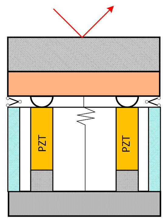
Figure 1.
Schematic diagram of PZT FSM.
Hysteresis exists widely in devices with PZT as an actuator. Due to the inverse piezoelectric effect, a deviation occurs in the displacement curve of the PZT actuator when the voltage rises and falls. This results in a severe nonlinear effect between input and output. For PZT FSM, hysteresis is manifested in the nonlinear, multi-valued, and non-single-path relationship between the control voltage and the mirror deflection angle. The hysteresis characteristic is also related to the frequency of the control signal, which is rate-dependent.
Figure 2 shows the hysteresis curve measured using a certain type of PZT FSM, and the red arrow indicates the direction of the beam. Figure 2a shows the hysteresis curve with the same input signal amplitude but different frequencies; Figure 2b shows the hysteresis curve with the same input signal frequency but different amplitudes. The test results show that when the input signal is a voltage signal with the same amplitude but varying frequencies, the hysteresis curve appears as follows: When driven by a higher-frequency voltage, the hysteresis curve becomes wider, the output displacement range decreases, and the hysteresis curve rotates clockwise. When the input signal is a voltage signal with the same frequency but varying amplitudes, the hysteresis curve appears as follows: When driven by a larger amplitude voltage, the hysteresis curve becomes wider and the output displacement range increases.
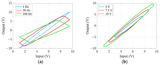
Figure 2.
Characteristics of hysteresis curves: (a) The hysteresis curve when the frequency changes. (b) The hysteresis curve when the amplitude changes.
2.2. P-I Model Based on Play Operator
The P-I model is a phenomenological model that relies on the relationship between the system’s input and its output. Its core involves a weighted overlay of hysteresis units, such as play and stop operators. It possesses the characteristics of rapid calculation speed and broad applicability. This paper introduces a P-I model based on the play operator to simulate hysteresis characteristics. The relationship between the input signal, denoted as x, and the output signal, denoted as y, of the play operator is illustrated in Figure 3. And the arrow direction is the direction in which the output signal changes when the input signal changes.
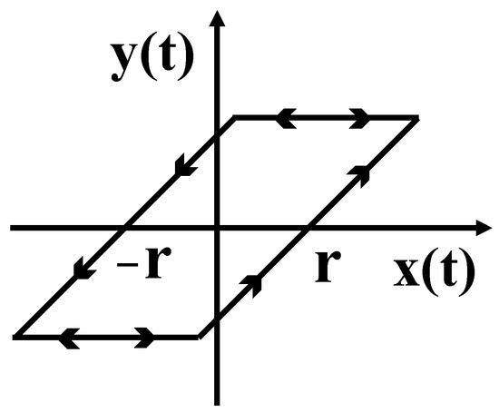
Figure 3.
Play operator.
The equation for the play operator is:
where , ; is the segmented monotonic input signal; and is the play operator threshold value.
The initial condition is:
The P-I model is obtained through a weighted overlay of multiple play operators with different thresholds. The equation is:
where is the weight of play operator; is the threshold value of play operator, ; and n is the number of play operators.
The P-I model is established using the above equations, and a simulation analysis is conducted. Figure 4 shows the hysteresis curve of the P-I model when inputs are triangular wave signals with both constant and changing amplitudes.
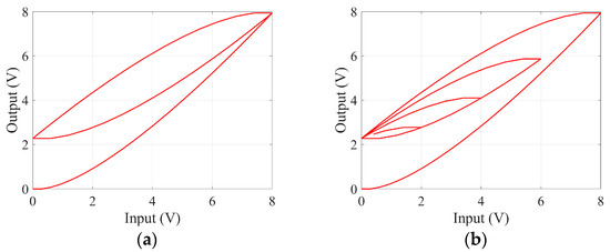
Figure 4.
(a) The amplitude of the input signal remains unchanged. (b) The amplitude of the input signal changes.
According to Figure 4, the hysteresis curve described by the P-I model is consistent with the hysteresis characteristics observed in the PZT FSM test. Therefore, by adjusting and in the P-I model, we can model the PZT FSM hysteresis curve, and then it can be used to compensate and suppress the nonlinear errors caused by hysteresis. However, the model is a static nonlinear model, meaning that it is unaffected by the frequency of the input signal. As mentioned in the previous section, the hysteresis is influenced by the frequency of the input signal. Therefore, in order to meet the application requirements of the fine tracking system, it is necessary to establish a dynamic hysteresis model related to the input signal frequency.
2.3. Rate-Dependent Hysteresis Model Based on P-I
To establish the rate-dependent model of the PZT FSM, this paper adopts a Hammerstein structure, which combines the static nonlinear P-I model with the dynamic linear model in series. The structure is shown in Figure 5. u is the input signal and y is the output signal.

Figure 5.
The structure of the P-I rate-dependent model.
The dynamic linear model’s equation is:
where , .
Figure 6 depicts the hysteresis curve of the P-I rate-dependent model when the input signals are the same amplitude but different frequencies. Thus, it can be seen that it has the same characteristics as the PZT FSM when the frequency of the input signal changes.
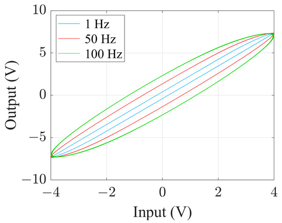
Figure 6.
The hysteresis curve of the P-I rate-dependent model with different input signal frequencies.
2.4. Feedforward Control Based on Inverse Model
In order to reduce the influence of hysteresis nonlinearity, feedforward control is one of the effective methods. In this paper, the inverse model of the P-I rate-dependent model is established. It is designed as a feedforward controller and compensates for hysteretic nonlinear errors by being in series with PZT FSM. The structure is shown in Figure 7.

Figure 7.
The structure of feedforward control based on the inverse model.
The relationship between the hysteresis model and its inverse model is shown in Figure 8. The inverse hysteresis model is also a nonlinear model, and it is symmetric with the hysteresis model about the 45° line. Therefore, the input signal is calculated using the inverse model and then utilized to control the PZT FSM. Then, the input signal and the output signal of the feedforward system are linear.
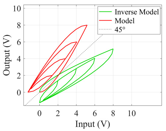
Figure 8.
Hysteresis model and its inverse model.
To address the high-frequency input signals of the fine tracking system, this paper establishes a rate-dependent hysteresis model consisting of a P-I model and a dynamic linear model. Therefore, it is necessary to establish the inverse model separately for these two models.
First, the P-I model’s inverse model is:
where is the weight and is the threshold value.
Next, the dynamic linear model’s inverse model is:
The feedforward controller consists of the above two inverse models. Feedforward control belongs to open-loop control; its anti-interference ability and stability are limited. For the fine tracking system, due to the interference of external factors such as vibration, it is difficult to achieve the ideal control effect only using feedforward control. Therefore, employing compound control that combines feedforward control and feedback control proves to be an effective method.
2.5. Compound Control Method
The structure of the compound control method is shown in Figure 9. u is the input signal of the control system; y is the output signal of the control system. The feedforward controller is the inverse model of the P-I rate-dependent model, and the feedback controller is PID control method. The equation is:
where is the difference between the reference input and the actual output; Kp is the proportional coefficient; Ti is the integral time coefficient; and Td is the differential time coefficient.

Figure 9.
Compound control method block diagram.
The compound control method combines the advantages of feedforward control and feedback control, offering strong anti-interference capabilities and stability. It is particularly suitable for the fine tracking systems with external interference and high-frequency fast tracking signals.
2.6. Simulation Analysis of Fine Tracking System Performance
Based on the structure of the fine tracking control system, a simulation system for dynamic target tracking is constructed. The P-I rate-dependent hysteresis model represents the PZT FSM, and its inverse model represents the feedforward controller; the feedback controller is the PID control method.
To explore the impact of hysteresis compensation on the performance of the fine tracking control system, this paper simulates and compares three different control methods. The PID controller parameters are adjusted under the same conditions for all control methods.
- Single-PID feedback control: The PID controller parameters are Kp: 0.15; Ti: 170.2; and Td: 0.00026.
- The compound control which combines P-I model feedforward control and PID feedback control: The PID controller parameters are Kp: 0.11; Ti: 301.3; and Td: 0.00051.
- The compound control which combines P-I rate-dependent model feedforward control and PID feedback control: The PID controller parameters are Kp: 0.18; Ti: 351.7; and Td: 0.00048.
A sinusoidal signal whose frequencies increase from 1 Hz to 400 Hz and amplitudes decrease exponentially was utilized to simulate vibration with a rapid frequency change. The error suppression capabilities of the above three control methods were tested. Figure 10 shows the error between the system output and input signals and Figure 11 shows the error suppression bandwidth of the system.
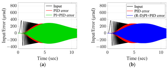
Figure 10.
Comparison of control effect of three control methods in the time domain. (a) PI + PID compared with PID. (b) (R-D)PI + PID compared with PID.
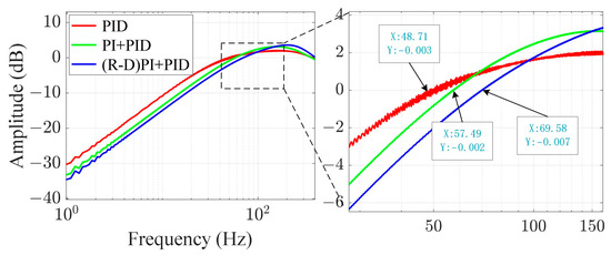
Figure 11.
Comparison of error suppression bandwidth.
According to the simulation results, the error suppression bandwidth of the single-PID feedback control system is approximately 48.7 Hz. When adding feedforward compensation based on the P-I model, the error suppression bandwidth is approximately 57.5 Hz. When adding feedforward compensation based on the P-I rate-dependent model, the error suppression bandwidth is approximately 69.6 Hz. This represents an improvement of about 43.75%. It is proven that feedforward compensation for hysteresis can effectively enhance the closed-loop tracking performance of the fine tracking control system. Additionally, the effect of using feedforward compensation based on a P-I rate correlation model is better.
3. Results
3.1. Identification and Testing of Hysteresis Model
Based on the test results, when the input signal frequency is lower than 5 Hz, the hysteresis curve of the PZT FSM experiences minimal changes, approximately resembling a static hysteresis system. Therefore, the parameters of the P-I model are identified as low-frequency. In this paper, 10 play operators are employed to fit hysteresis curves. The resulting fitting values for the weight coefficient and the threshold coefficient are as follows:
ω = [0.3695, 0.1983, 0.1232, …, 0.0369]T
r = [0, 210, 420, …, 1890]T
Figure 12 shows the hysteresis curve of the P-I model and the measured hysteresis curve of the PZT FSM when the input signal is 1 Hz. It can be observed that the hysteresis curve of the P-I model is particularly similar to the measured curve of the PZT FSM, thereby confirming the high accuracy of the modeling.
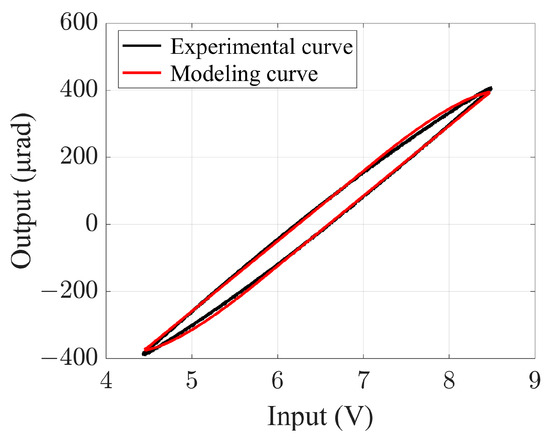
Figure 12.
Hysteresis curves of model and measured at 1 Hz.
Next, the sinusoidal signals with a wide frequency range are inputted into both the P-I model and the PZT FSM. The output data from these two parts are used as the inputs and outputs to identify the parameters of the dynamic linear model. The results are as follows:
Figure 13 shows the hysteresis curve of the P-I rate-dependent model and the measured hysteresis curve of PZT FSM, when the input signals are in the middle- and high-frequency ranges. It can be observed that the modeling has a high accuracy. So far, the hysteresis model of the PZT FSM has been established, and the feedforward controller will be designed using its inverse model.
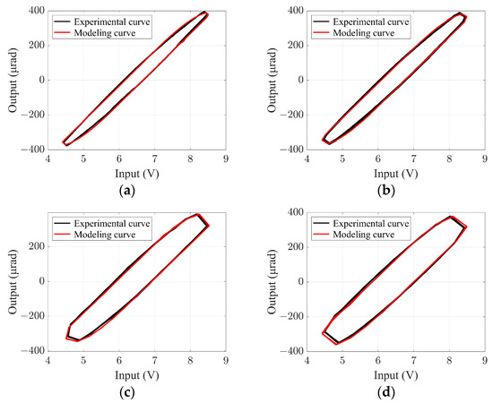
Figure 13.
Hysteresis curves of model and measured at middle and high frequencies. (a) 10 Hz, (b) 20 Hz, (c) 40 Hz, (d) 50 Hz.
3.2. Open-Loop Pointing Accuracy Test
The feedforward controller was designed using the hysteresis model, and an open-loop feedforward compensation experiment was conducted for the PZT FSM. Three control methods were compared, which are direct control, feedforward control based on the PI model, and feedforward control based on the PI rate-dependent model. The signal generator generates sinusoidal input signals, and the output signals are collected by an angle sensor inside the PZT FSM. The sampling frequency is 1 kHz. Since the coarse tracking turntable’s tracking errors are about ±400 μrad, the fine tracking system is required to track signals with amplitudes below 400 μrad. Therefore, the input signal amplitude for the open-loop tracking experiment is set to 400 μrad.
The results of the open-loop tracking experiment are shown in Figure 14. The experimental results show that the feedforward control methods can enhance the tracking accuracy of PZT FSM, and when the tracking signals are in the middle- and high-frequency ranges, the feedforward control based on the P-I rate-dependent model exhibits even higher tracking accuracy. The root mean square (RMS) and peak-to-peak (P-P) values of the tracking errors are shown in Table 1 and Table 2.
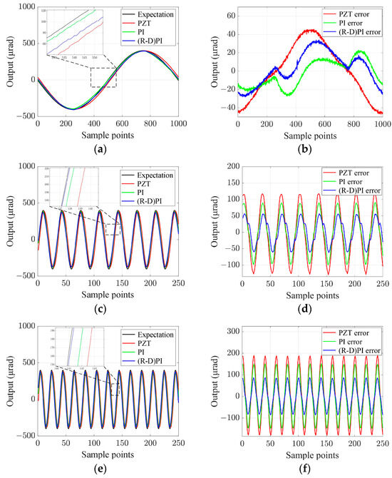
Figure 14.
Sinusoidal tracking and tracking errors. (a) 1 Hz tracking, (b) 1 Hz tracking errors, (c) 30 Hz tracking, (d) 30 Hz tracking errors, (e) 50 Hz tracking, (f) 50 Hz tracking errors.

Table 1.
RMS values of tracking error for three control methods.

Table 2.
P-P values of tracking error for three control methods.
3.3. Setting up the Experimental Platform
As shown in Figure 15, the experimental platform of the fine tracking control system was set up. The laser acted as an optical source. The embedded digital signal processor was used as the main control unit, and the high-speed CCD camera served as a measuring unit for target spot’s position. The high-speed movement of the target in the azimuth and elevation directions was simulated by controlling the disturbance FSM. The optical path of the experimental platform is depicted in Figure 16.
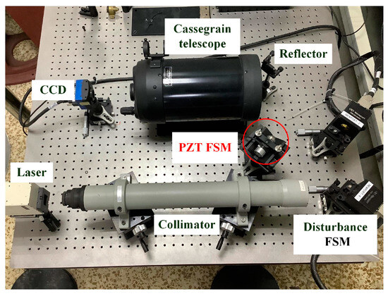
Figure 15.
Experiment platform.
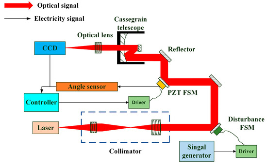
Figure 16.
The optical path of the experimental platform.
3.4. Dynamic Target Tracking Experiment
Based on the experimental platform of the fine tracking control system, this paper conducted a dynamic target tracking experiment to verify the impact of feedforward control on the system’s tracking performance. Disturbance signals with an amplitude of ±400 μrad and a frequency range of 1 Hz to 200 Hz were generated with the disturbance FSM. Miss distance data were collected with the CCD camera. Subsequently, the PZT FSM was controlled to track the target for the purpose of suppressing disturbances.
In this dynamic target tracking experiment, we also compared three control methods: single-PID feedback control, the compound control which combines P-I model feedforward control and PID feedback control, and the compound control which combines P-I rate-dependent model feedforward control and PID feedback control.
First, this paper tested the nonlinearity of the input and output of the PZT FSM for the above three control methods, and the results are shown in Figure 17.
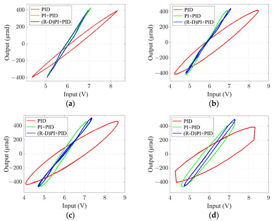
Figure 17.
The results of nonlinear testing. (a) 1 Hz, (b) 20 Hz, (c) 30 Hz, (d) 50 Hz.
After calculating the nonlinearity, it was found that when the input signal frequency is 1 Hz, the nonlinearity finally decreases from 11.17% to 5.75%. When the input signal frequency is 30 Hz, the nonlinearity finally decreases from 31.66% to 6.13%. When the input signal frequency is 50 Hz, the nonlinearity finally decreases from 41.57% to 7.21%. It can be observed that feedforward control effectively reduces the nonlinearity of the PZT FSM while enhancing the response speed of the fine tracking system.
Next, this paper collected the tracking errors of the three control methods using the CCD camera and compared them with the disturbance signals. The comparison results are shown in Figure 18.
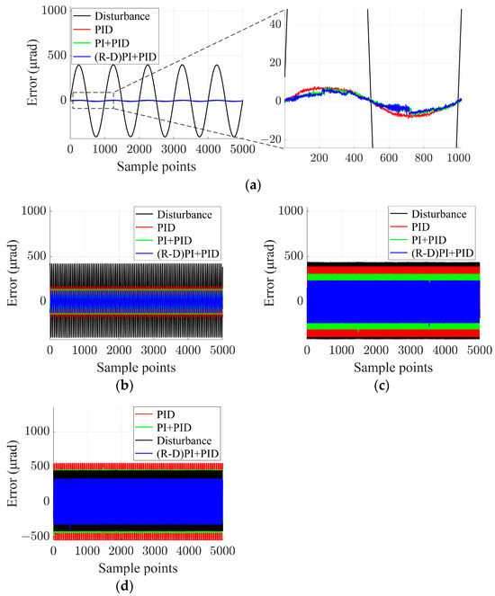
Figure 18.
Comparison of tracking error of three control methods. (a) 1 Hz, (b) 20 Hz, (c) 30 Hz, (d) 50 Hz.
The test data at each frequency were transformed into the frequency domain and analyzed to determine the system’s error suppression bandwidth for the three control methods. The results are shown in Figure 19.
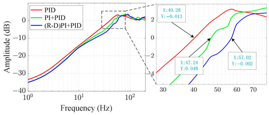
Figure 19.
Error suppression bandwidth of three control methods.
According to the experimental results, the error suppression bandwidth of the single-PID feedback control system is approximately 40.3 Hz. When adding feedforward compensation based on the P-I model, the error suppression bandwidth is approximately 47.2 Hz. When adding feedforward compensation based on the P-I rate-dependent model, the error suppression bandwidth is approximately 57 Hz. This represents an improvement of about 41.71%. The comparison of experimental results and simulation results is shown in Table 3. Due to the influence of experimental conditions and other factors, the system’s error suppression bandwidth in the experimental test is lower compared to the simulation results. However, the relative improvement effect is consistent with the simulation results.

Table 3.
Comparison of simulation results and experimental results of error suppression bandwidth of the fine tracking system.
Consequently, suppressing the disturbance caused by hysteresis can improve the error suppression ability of the fine tracking system.
4. Discussion
Using the existing experimental platform, we successfully enhanced the error suppression bandwidth of the fine tracking system and verified the influence of the hysteresis characteristics of PZT FSM on the error suppression bandwidth based on the experimental results. Compared to the traditional closed-loop control method, this method improves the nonlinearity of PZT FSM without reducing its response speed. Additionally, the experimental results are similar to the simulation results. It is worth noting that the hysteresis nonlinearity of PZT FSM will affect the performance of the fine tracking system. Therefore, we can focus on improving the accuracy of the hysteresis model in future research in order to further enhance the performance of the fine tracking control system. At the same time, the feedback controller can also be further improved.
5. Conclusions
In this paper, considering the demand for high control accuracy in the fine tracking system, we proposed a compound control method that combines P-I rate-dependent model feedforward control with PID feedback control. Firstly, we established a rate-dependent hysteresis model and designed the feedforward controller based on its inverse model. Then, we conducted a simulation analysis. Finally, we set up the experimental platform for the fine tracking system to verify the high accuracy of the P-I rate-dependent hysteresis model across a range of frequencies, from low to high, and confirmed the optimization effect of compensating for hysteresis nonlinearity on the fine tracking system. The experimental results show that the nonlinearity of the PZT FSM is improved by 30% in the middle- and high-frequency ranges, and the error suppression bandwidth of the fine tracking system is improved by 41.7%.
The experimental results show that the linearity of PZT FSM and the error suppression bandwidth of the fine tracking control system significantly improved. Therefore, this method is applicable not only to various laser communication systems but also to optical dynamic target tracking systems based on PZT FSM. In the future, we will further improve the system model and simultaneously investigate other disturbances within the fine tracking control system, adopting effective methods to suppress them.
Author Contributions
Methodology, F.L. and Y.L.; Software, F.L. and Y.L.; Formal analysis, F.L. and Y.L.; Writing—Original draft, F.L.; Writing—Review and editing, F.L., Y.L., S.G., H.W. and F.G.; Supervision, S.G. All authors have read and agreed to the published version of the manuscript.
Funding
This research was funded by the National Natural Science Foundation of China (No. 11973041, No. 12122304) and the Youth Innovation Promotion Association of Chinese Academy of Sciences (No. 2019218).
Institutional Review Board Statement
Not applicable.
Informed Consent Statement
Not applicable.
Data Availability Statement
Not applicable.
Acknowledgments
The authors would like to thank the anonymous reviewers for their valuable comments and suggestions.
Conflicts of Interest
The authors declare no conflict of interest.
References
- Kaushal, H.; Kaddoum, G. Optical Communication in Space: Challenges and Mitigation Techniques. IEEE Commun. Surv. Tutor 2017, 19, 57–96. [Google Scholar] [CrossRef]
- Zhang, G.; Wu, J.; Li, Y. A Review of Variable-Beam Divergence Angle FSO Communication System. Photonics 2023, 10, 756. [Google Scholar] [CrossRef]
- Takenaka, H.; Carrasco-Casado, A.; Fujiwara, M.; Kitamura, M.; Sasaki, M.; Toyoshima, M. Satellite-to-Ground Quan-tum-Limited Communication Using a 50-Kg-Class Microsatellite. Nat. Photonics 2017, 11, 502–508. [Google Scholar] [CrossRef]
- Do, P.X.; Carrasco-Casado, A.; Hosonuma, T.; Toyoshima, M.; Nakasuka, S. A Study on Optimizing Laser Beam Waist for LEO-To-GEO Communication for 100 Kg-Class Satellite. In Proceedings of the 2020 International Conference on Communications, Computing, Cybersecurity, and Informatics (CCCI), Sharjah, United Arab Emirates, 3–5 November 2020; IEEE: Sharjah, United Arab Emirates, 2020; pp. 1–6. [Google Scholar] [CrossRef]
- Ma, J.G.; Tang, T. Review of compound axis servomechanism tracking control technology. Infrared Laser Eng. 2013, 42, 218–227. (In Chinese) [Google Scholar] [CrossRef]
- Wang, W.; Han, F.; Chen, Z. Modeling and Compensation for Asymmetrical and Dynamic Hysteresis of Piezoelectric Actuators Using a Dynamic Delay Prandtl–Ishlinskii Mode. Micromachines 2021, 12, 92. [Google Scholar] [CrossRef] [PubMed]
- Suzuki, H.; Wood, R.J. Origami-inspired miniaturemanipulator for teleoperated microsurge. Nat. Mach. Intell. 2020, 2, 437–446. [Google Scholar] [CrossRef]
- Zhang, C.; Song, Y. A novel design method for 3D elliptical vibration-assisted cutting mechanism. Mech. Mach. Theory 2019, 134, 308–322. [Google Scholar] [CrossRef]
- Feng, Y.; Liu, J.; Li, H. Deposition behavior optimization of on-demand tin droplet with gravity based on piezoelectric micro-je. Int. J. Heat Mass Transf. 2022, 192, 122902. [Google Scholar] [CrossRef]
- Li, Y.; Xu, Q. Design and analysis of a totally decoupled flexure-based XY parallel micromanipulato. IEEE Trans. Robot. 2009, 25, 645–657. [Google Scholar] [CrossRef]
- Wang, W.; Deng, J.; Liu, Y. Design modeling and experiment of a miniature biped piezoelectric robot. Smart Mater. Struct. 2022, 31, 075004. [Google Scholar] [CrossRef]
- Zhang, S.J.; Liu, Y.X.; Deng, J. Developmentof a low capacitance two-axis piezoelectric tilting mirror used for optical assisted micromanipulatio. Mech Syst Signal Process. 2021, 154, 107602. [Google Scholar] [CrossRef]
- Li, Q.; Liu, L.; Ma, X. Development of multitarget acquisition, pointing, and tracking system for airborne laser communicatio. IEEE Trans Indust. Inform. 2018, 15, 1720–1729. [Google Scholar] [CrossRef]
- Cao, K.; Hao, G.; Li, B. Modified steady tracking strategy for composite axes system in free-space laser communication. Opt. Eng. 2023, 62, 078101. [Google Scholar] [CrossRef]
- Wang, C.; Wang, Y.; Hu, L. Hysteresis compensation of the piezoelectric ceramic actuators–based tip/tilt mirror with a neural network method in adaptive optics. Opt. Eng. 2016, 55, 054107. [Google Scholar] [CrossRef]
- Zhong, J.; Nishida, R.; Shinshi, T. Design and Precision Tracking Control of a High-Bandwidth Fast Steering Mirror for Laser Beam Machining. Precis. Eng. 2022, 73, 128–139. [Google Scholar] [CrossRef]
- Habibulla, H. 30 Years of atomic force microscopy: Creep, hysteresis, cross-coupling, and vibration problems of piezoelectric tube scanner. Measurement 2020, 159, 107776. [Google Scholar] [CrossRef]
- Harper, P.G. Kinematic theory of piezoelectric hysteresis. J. Appl. Phys. 1981, 52, 6851–6855. [Google Scholar] [CrossRef]
- Zhang, Y.; Sun, M.; Song, Y.; Zhang, C.; Zhou, M. Hybrid Adaptive Controller Design with Hysteresis Compensator for a Piezo-Actuated Stage. Appl. Sci. 2022, 13, 402. [Google Scholar] [CrossRef]
- Sabarianand, D.V.; Karthikeyan, P.; Muthuramaing, T. A review on control strategies for compensation of hysteresis and creep on piezoelectric actuators based micro systems. Mech. Syst. Signal Process. 2020, 140, 106634. [Google Scholar] [CrossRef]
- Gan, J.; Zhang, X. A review of nonlinear hysteresis modeling and control of piezoelectric actuators. AIP Adv. 2019, 9, 040702. [Google Scholar] [CrossRef]
- Nie, L.; Luo, Y.; Gao, W. Rate-dependent asymmetric hysteresis modeling and robust adaptive trajectory tracking for piezoelectric micropositioning stage. Nonlinear Dyn. 2022, 108, 2023–2043. [Google Scholar] [CrossRef]
- Mörée, G.; Leijon, M. Review of Play and Preisach models for hysteresis in magnetic material. Materials 2023, 16, 2422. [Google Scholar] [CrossRef] [PubMed]
- Baziyad, A.G.; Ahmad, I.; Salamah, Y.B. Precision Motion Control of a Piezoelectric Actuator via a Modified Preisach Hysteresis Model and Two-Degree-of-Freedom H-Infinity Robust Control. Micromachines 2023, 14, 1208. [Google Scholar] [CrossRef]
- Zhou, C.; Feng, C.; Aye, Y.N. A digitized representation of the modified Prandtl–Ishlinskii hysteresis model for modeling and compensating piezoelectric actuator hysteresis. Micromachines 2021, 12, 942. [Google Scholar] [CrossRef] [PubMed]
- Li, Z.; Shan, J.; Gabbert, U. Inverse compensation of hysteresis using Krasnoselskii-Pokrovskii mode. IEEE ASME Trans. Mechatron. 2018, 23, 966–971. [Google Scholar] [CrossRef]
- Ismail, M.; Ikhouane, F.; Rodellar, J. The hysteresis Bouc-Wen model, a surve. Arch. Comput. Methods Eng. 2009, 16, 161–188. [Google Scholar] [CrossRef]
- Yang, L.; Zhao, Z.; Zhang, Y.; Li, D. Rate-Dependent Modeling of Piezoelectric Actuators for Nano Manipulation Based on Fractional Hammerstein Model. Micromachines 2021, 13, 42. [Google Scholar] [CrossRef]
- Wang, L.T.; Zhang, Y.P.; Xu, Y.L. Dual-loop control strategy for fast-steering mirror driven by PZT. Chin. J. Sci. Instrum. 2014, 35, 68–72. (In Chinese) [Google Scholar]
- Wang, Y.K.; Hu, L.F.; Wang, C.C. Adaptive inverse control for tip/tilt mirror in adaptive optical system. Opt. Precis. Eng. 2015, 23, 2203–2210. (In Chinese) [Google Scholar] [CrossRef]
- Wang, G.; Rao, C. Adaptive control of piezoelectric fast steering mirror for high precision tracking applicatio. Smart Mater. Struct. 2015, 24, 035019. [Google Scholar] [CrossRef]
- Wittig, M.E.; Van Holtz, L.; Tunbridge, D.E.L.; Vermeulen, H.C. In-Orbit Measurements of Microaccelerations of ESA’s Communication Satellite Olympus; Begley, D. In Proceedings of the Free-Space Laser Communication Technologies II, Los Angeles, CA, USA, 15–17 January 1990; Begley, D.L., Seery, B.D., Eds.; pp. 205–214. [Google Scholar] [CrossRef]
Disclaimer/Publisher’s Note: The statements, opinions and data contained in all publications are solely those of the individual author(s) and contributor(s) and not of MDPI and/or the editor(s). MDPI and/or the editor(s) disclaim responsibility for any injury to people or property resulting from any ideas, methods, instructions or products referred to in the content. |
© 2023 by the authors. Licensee MDPI, Basel, Switzerland. This article is an open access article distributed under the terms and conditions of the Creative Commons Attribution (CC BY) license (https://creativecommons.org/licenses/by/4.0/).