Article

Nonreciprocal Propagation of Nematicons

1
School of Mathematics, University of Edinburgh, Edinburgh EH9 3FD, UK
2
NooEL—Nonlinear Optics and OptoElectronics Lab, DIIEM-University “Roma Tre”, 00146 Rome, Italy
*
Author to whom correspondence should be addressed.
Photonics 2023, 10(10), 1144; https://doi.org/10.3390/photonics10101144
Submission received: 20 September 2023 / Revised: 4 October 2023 / Accepted: 11 October 2023 / Published: 12 October 2023
(This article belongs to the Special Issue Liquid Crystals in Photonics)

Abstract

:
We model two-port nonlinear optical isolators based on solitary waveguides in planar cells with non-homogeneously oriented liquid crystals in the nematic phase. In a planar layout with molecular anchoring linearly changing along the sample length or across its width, we conduct numerical experiments on the excitation and propagation of reorientational solitons—“nematicons”—launched in opposite directions from the two ends of the cell. Specifically, in the Kerr-like diffractionless regime corresponding to graded-index waveguides for copolarized weak signals, we investigate the non-overlapping trajectories of forward and backward propagating wavepackets. The resulting non-specular transmission entails optical isolation and diode-like behavior as light propagating backwards does not reach the forward input. The response dependencies on input power, range of angular modulation, and one-photon losses are analyzed with reference to parameters of realistic soft matter.

1. Introduction

Optical isolators, particularly those in guided-wave formats, are elements able to prevent a back-launched (BP) light signal from reaching the input port of the forward-propagating (FP) excitation [1]. There has been a large revamped interest in optical diodes, with most common isolators based on the Faraday effect and magnetic fields, phonon–photon interactions, resonances, interband transitions, photonic crystals and multilayers, nanoparticles and metamaterials, and time- and spatio-temporal modulation, in conjunction with nonlinear, electro-optic, acousto-optical responses or losses [2,3,4,5,6,7,8,9,10,11,12,13,14,15,16,17,18,19,20,21,22,23,24,25,26,27]. Reciprocity breaking in such devices is achieved by the use of either some bias or an all-optical nonlinearity in the presence of asymmetry [28]. Even when three-wave mixing for parametric generation such as frequency doubling (rather than four-wave or Kerr effect) was employed to realize optical diodes, a nonsymmetrically located defect in a quasi-phase-matched waveguide was exploited to achieve one-way transmission of the FP injected fundamental frequency, with the BP light entirely converted to the second-harmonic [4,5,6]. At variance with changes in wavelength, some schemes entail isolation through changes in the transmitted polarization [3] or output/input ports [2,15]. The phenomenon we address in this work can be framed in the latter category, as we investigate self-induced waveguides which, by launching intense beams from the opposite ends of a specific sample, establish signal pipelines with distinguishable paths, as alluded in [29]. Hence, the all-optical waveguide connecting the FP input to its output port after propagation does not overlap with the self-waveguide formed between the FP and the BP outputs, as illustrated in Figure 1. Otherwise stated, FP and BP solitary waves across the sample undergo distinguishable evolutions and trajectories, somewhat generalizing the results presented in [28]. Here, we deal with uniaxial liquid crystals with planarly aligned nematogenic molecules in the principal plane of propagation of extraordinary light wavepackets in the diffractionless solitary regime stemming from reorientation, namely nematicons [30,31,32]. We specifically examine the generation and path of extraordinary-wave nematicons in planar cells of nematic liquid crystals (NLC) when launching identical beams from the opposite ends of samples with linearly modulated angle distributions of the optic axis. In such NLC geometries, the combination of (i) a varying orientation across either the transverse coordinate y or along the propagation coordinate z and (ii) the reorientational all-optical response supporting self-confinement yields direction-dependent soliton waveguides with non-reversible routing.

2. Model

We consider positive uniaxial nematic liquid crystals with a large order parameter close to unity and nematogenic molecules aligned in the plane ( y , z ) where extraordinary (e-) waves at optical frequencies propagate, i.e., with electric field components E y and E z , vacuum wavevector k = 2 π z / λ at wavelength λ , Poynting vector S in ( y , z ) at the walkoff angle δ with respect to k . Due to the anisotropy of the elongated molecules, with long axis parallel to the optic axis and the molecular director n in the birefringent medium, the highest value of the refractive index n corresponds to an (extraordinary) E-field aligned with n , the lowest value n o = n to an (ordinary) E-field orthogonal to n , with the plane-wave eigenfields, ordinary E o and extraordinary E e , being mutually perpendicular. Denoting by θ the angle formed by k and n , for a given plane wave with phase velocity along k , the e-wave refractive index varies between the eigenvalues n and n as
n e ( θ ) = n n n 2 ϵ a sin 2 θ ,
whereas the walk-off angle obeys the expression
δ ( θ ) = arctan ϵ a sin 2 θ ϵ a + 2 n 2 + ϵ a cos 2 θ ,
with ϵ a = n 2 n 2 , the optical dielectric anisotropy. Throughout this work, we consider θ = θ ( y , z ) , as provided by molecular anchoring at upper and lower glass substrates in standard planar cells containing the NLC. We examine geometries of length L, width d, and thickness h along z , y , and x, respectively, with ( x , y , z ) a standard system of mutually orthogonal axes. The cells are taken with h d , L , but h is much larger than the spot-size W of the nonlinear wavepacket. The latter entails self-confined fully three-dimensional beams to travel through the sample with no interactions with the boundaries [33]. When an electromagnetic wavepacket of wavevector k and electric field E polarized in the plane ( y , z ) propagates in the NLC sample with molecular director n in the same plane ( y , z ) , the reaction between the polarization field P = ϵ 0 χ ¯ ¯ E , and E results in a rotational torque Γ = P × E which, acting on the molecular dipoles, increases the orientation θ by a nonlinear amount ψ , thereby producing a Kerr-like self-focusing with n e ( Θ ) > n e ( θ ) , being Θ = θ + ψ and ψ θ in the usual weak nonlinear regime. The equilibrium distribution of the molecular director n is therefore determined by the balance between the torque Γ and the elastic forces acting in the liquid state. When n is perpendicular to the electric field, reorientation of plane waves can only occur above a power threshold, known as optical Freedericksz transition; this can be prevented by imposing an arbitrary nonzero orientation θ in the principal plane ( y , z ) or relying on a finite angular spectrum of wavevectors, i.e., a finite-size beam [34].
Nematicons stem from the robust balance between linear diffraction and nonlinear e index increase n e = n e [ Θ ( x , y , z ) ] n e [ θ ( y , z ) ] + ψ d n e ( θ ) / d θ in the planar geometries of interest and in the presence of a nonlocal and saturable all-optical response [35,36]. The latter gives rise to graded-index channel waveguides featuring large numerical aperture and able to confine e polarized signals, with energy-flux propagating at an angle δ with respect to the input wavevector.
For a light beam linearly polarized along y and propagating along z, neglecting vectorial effects and adopting the paraxial approximation (i.e., neglecting components E x and E z of the electric field), the evolution of the optical envelope E y is ruled by an anisotropic nonlinear Schrödinger-type equation [37]:
2 i k 0 n e E y z + 2 i k 0 n e E y y t a n [ δ ( Θ ) ] + 2 E y y 2 + k 0 2 n 2 cos 2 Θ + n 2 sin 2 Θ n 2 cos 2 θ 0 n 2 sin 2 θ 0 E y = 0 .
The above electromagnetic equation needs to be coupled to the NLC response given by the Frank–Oseen energy density f in non-chiral NLC:
f = 1 2 K 11 ( n ) 2 + 1 2 K 22 ( n · ( × n ) ) 2 + 1 2 K 33 ( n × ( × n ) ) 2 1 2 ϵ 0 Δ ϵ ( n · E ) 2 .
Here, K 11 , K 22 , K 33 are the Frank elastic constants for splay, twist and bend deformations of the molecular director n , respectively. The NLC elastic response is obtained by taking variations of this free energy. Since in the specific (1 + 1)D geometry under consideration the molecular director and the electric field of the beam lie in the principal plane ( y , z ) , then n = ( 0 , sin Θ , cos Θ ) and the associated Euler–Lagrange equation leads to the director rotation
K 22 2 Θ x 2 + ( K 11 cos 2 Θ + K 33 sin 2 Θ ) 2 Θ y 2 + K 33 K 11 2 sin 2 Θ Θ y 2 + ϵ 0 Δ ϵ 2 E 2 sin 2 Θ = 0 .
In the single constant approximation, whereby the elastic deformations are taken as equal, i.e., K 11 = K 22 = K 33 = K , the reorientation equation above can be recast as
K 2 Θ y 2 + 1 4 ϵ 0 Δ ϵ | E | 2 sin 2 Θ = 0 .
The nematicon model Equations (3) and (6) are difficult to solve in general [38]. In the frame of the first-order perturbation theory, taking the all-optical reorientation ψ to be much smaller than the background orientation θ and expanding the trigonometric functions, the equations reduce to
2 i k 0 n e E z + E y t a n [ δ ( θ + ψ ) ] + 2 E y 2 + k 0 2 Δ ϵ sin 2 θ sin 2 θ 0 + sin ( 2 θ ) ψ E = 0 ,
K 2 ψ y 2 + 1 4 ϵ 0 Δ ϵ | E | 2 sin ( 2 θ ) = 0 .
It is noteworthy that Equation (7) accounts for the all-optical (power dependent) changes in walkoff [39].
In this study, we consider the simple limiting cases of either a purely longitudinal modulation θ = θ ( z ) or a purely transverse modulation θ = θ ( y ) , as sketched in Figure 2. First, we consider the linear modulation of the orientation angle at rest in the transverse coordinate, θ = θ ( y ) as sketched in Figure 2a, namely,
θ = θ ( y ) = θ b o t + θ t o p θ b o t d y + d 2 .
Introducing the dimensionless coordinates ( Y , Z ) ,
y = λ π Δ ϵ Y , z = 2 n e λ π Δ ϵ Z
and amplitude u of the electric field envelope
E = 4 P b π ϵ 0 c n e W b 2 u ,
we obtain the unitless model
i u Z + i γ u Y t a n [ δ ( θ + ψ ) ] + 1 2 2 u y 2 + [ sin 2 θ sin 2 θ 0 + ψ sin ( 2 θ ) ] u = 0 ,
ν 2 ψ Y 2 + 2 sin 2 θ | u | 2 = 0
where λ is the wavelength, P b and W b the power and waste of the input beam, and θ 0 is the orientation at the launch-point ( Y , Z ) = ( Y 0 , 0 ) of the excitation. We define the elasticity parameter ν and walkoff coefficient γ as
ν = 2 π 3 c n e K W b 2 λ 2 P b , γ = 2 n e Δ ϵ .
The non-dimensionalization above is based on a Gaussian reference beam of power P b and half-width W b , whose values are taken below as P b = 2.7 mW and W b = 3.5 μ m, respectively, consistently with typical experimental parameters [30].
Next, we consider a purely longitudinal modulation of the orientation angle,
θ = θ ( z ) = θ 0 + ( θ L θ 0 ) z L
as shown in Figure 2b. The electric field Equation (7) can then be simplified using the phase transformation
E E exp i k 0 2 n e 0 z Δ ϵ ( sin 2 θ sin 2 θ 0 ) d u
to yield
2 i k 0 n e E z + E y t a n [ δ ( θ + ψ ) ] + 2 E y 2 + k 0 2 Δ ϵ sin ( 2 θ ) ψ E = 0 .
Here, we adopt the scaled coordinates ( Y , Z )
y = λ π Δ ϵ sin 2 θ 0 Y , z = 2 n e λ π Δ ϵ sin 2 θ 0 Z ,
the amplitude u of the electric field
E = 4 P b π ϵ 0 c n e W b 2 u
and
γ = 2 n e Δ ϵ sin ( 2 θ ( 0 ) ) , ν = 2 π 3 c n e K W b 2 λ 2 P b
to obtain the model
i u Z + i γ u Y t a n [ δ ( θ + ψ ) ] + 1 2 2 u Y 2 + 2 sin ( 2 θ ( Z ) ) sin ( 2 θ ( 0 ) ) ψ u = 0
ν 2 ψ Y 2 + 2 sin ( 2 θ ( Z ) ) sin ( 2 θ ( 0 ) ) | u | 2 = 0 .
In the numerical experiments, for either y- or z-dependent background orientation angles, we adopted material parameters typical of the NLC mixture E7 [40], with n = 1.7 , n = 1.5 , K = 1.2 × 10 11 N and elasticity/nonlocality ν = 250 . We considered a planar cell of size ( h , d , L ) = ( 30 , 600 , 1000 ) μ m, extraordinarily polarized Gaussian beams of wavelength 1064 nm launched forward in ( y 0 , 0 ) or backward in ( y F P ( L ) , L ) , with y F P ( L ) the transverse position of the outgoing F P wavepacket. The electric field equation was solved in Y using the fast-Fourier transform and propagated in Z according to a fourth-order Runge–Kutta scheme.

3. Results

The samples with modulated orientation angle θ encompass two main features as a propagating wavepacket evolves versus z in the plane ( y , z ) in the linear regime: (i) a non-uniform refractive index distribution n e = n e ( y ) versus y or n e = n e ( z ) along z with reference to the cells displayed in Figure 2a,b, respectively; the e-wave refractive index increases monotonically with θ according to Equation (1) as the orientation varies in the range 0 π / 2 ; (ii) a non-uniform walkoff δ ( θ ) which, according to Equation (2), in the interval ( 0 π / 2 ) is maximum close to π / 4 . For beams launched in the cell with k = ± z , the distribution n e = n e ( y ) introduces refraction and bending, as the walkoff shifts the Poynting vector S across y and makes a finite wavepacket travel through regions with differing phase velocities. At variance with transverse modulation, the longitudinal index modulation n e = n e ( z ) introduces no refraction for k = ± z , but the walkoff varies and bends the resulting trajectory [41].
The nonlinear regime, in which ψ is appreciable owing to all-optical reorientation, is characterized by a phase front distortion due to self-focusing, with an additional contribution to walk off as δ = δ ( θ + ψ ) ; moreover, the effective Kerr-like nonlinear response becomes inhomogeneous across the principal plane ( y , z ) , as the all-optical (Kerr-like) effective coefficient n 2 e f f depends on the background angle distribution [42], yielding
n 2 e f f ( θ ) = ϵ a 2 K sin 2 ( θ δ ) n e 2 ( θ ) tan δ .
Here, aiming at introducing the basic phenomenon, we illustrate the outcome of numerical integrations of the pertinent models in two sample cases, for purely transverse modulation and for purely longitudinal modulation, assuming a linearly varying orientation across either the width d or the length L of the cell, respectively (see Figure 2).
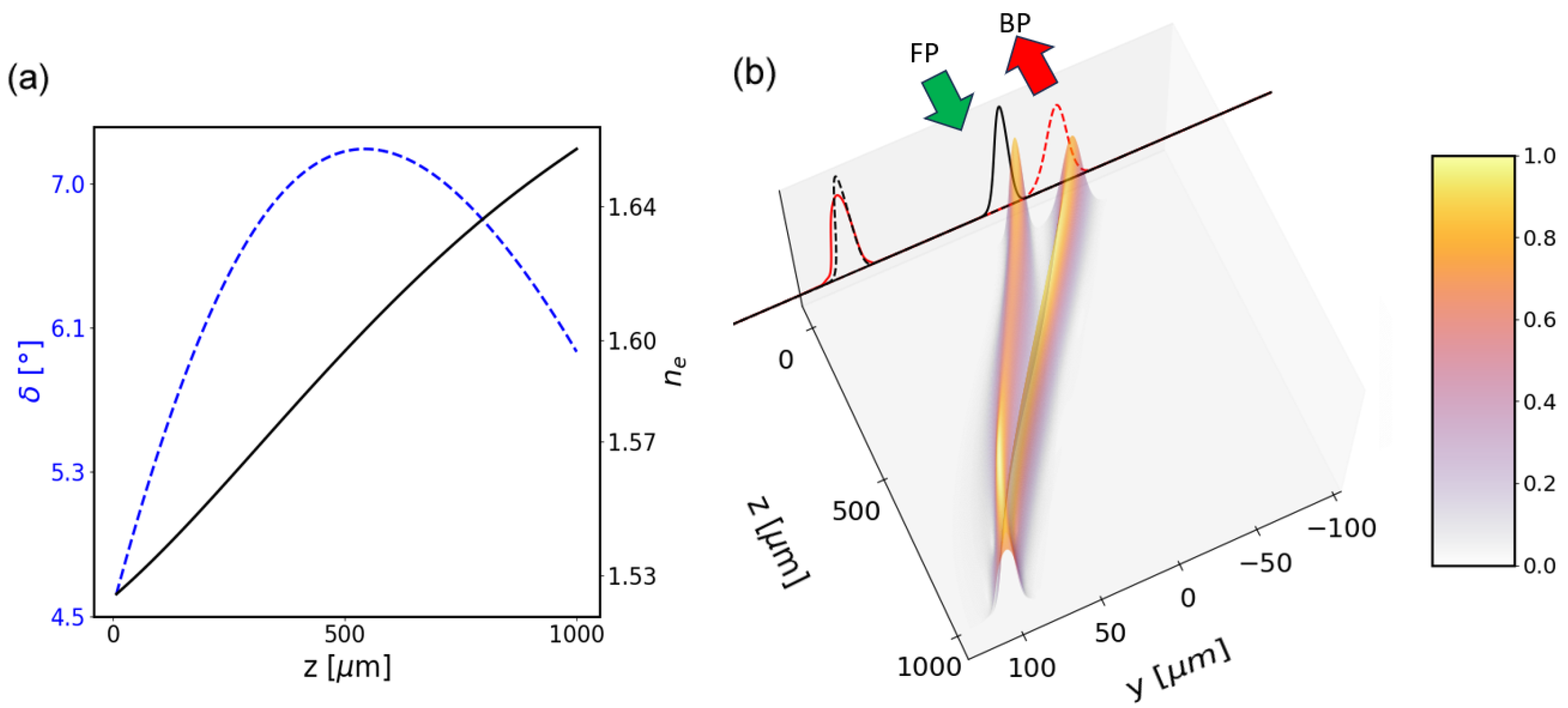
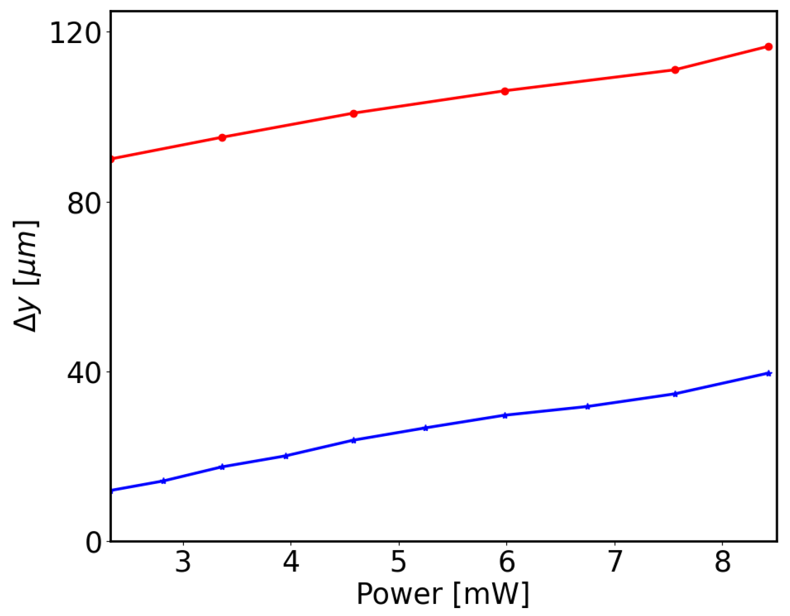
Figure 3 shows the case of a longitudinally modulated NLC sample with θ at rest linearly varying from θ 0 = 15 ° to θ L = 55 ° along the cell. Figure 3a graphs the background e-wave refractive index and walkoff distributions, whereas Figure 3b illustrates the core results: forward and backward soliton paths do not overlap despite the shared location of FP output and BP input and identical input envelopes, as underlined by the two-dimensional amplitude profiles plotted in z = 0 and z = L . In the examined regime, the beams are diffractionless as they self-confine; moreover, in the z-varying sample they undergo unequal birefringent walkoff and nonlinearity distributions (Equation (23)). Clearly, the resulting transverse separation Δ y between FP and BP nematicons/waveguides in z = 0 is excitation-level dependent, as graphed in Figure 4 (blue line).
At variance with the z dependent case, in a transversely modulated sample the refraction from the graded-index profile plays an additional role, as illustrated in the example of Figure 5 for orientation linearly varying from θ b o t = 30 ° in y b o t = 300 μ m to θ t o p = 50 ° in y t o p = 300 μ m. Figure 5a plots the background e-wave refractive index and walkoff, whereas Figure 5b is a three-dimensional graph of beam trajectory and profile evolutions. In this case, linear refraction tends to shift the beams from y b o t towards y t o p regardless the wavevector direction, with linear and nonlinear walkoff contributing to the resulting path in addition to the nonlinear distribution Equation (23).
The presence of one-photon propagation losses (i.e., E ( z ) = E ( 0 ) e α z ), associated with Rayleigh scattering even in undoped NLC, would marginally affect solitary wave generation and evolution in realistic samples, as shown in Figure 6a,b for the same two intervals of linearly modulated θ either along z or across y, respectively, and an average α = 5 cm 1 .

4. Discussion

As anticipated in the Introduction, the basic geometry we investigated is a two-port device where FP and BP e signals are guided within/by the reorientational solitary-waves excited by oppositely launched but otherwise identical light beams. The path of the backward nematicon does not overlap with the forward one; hence, the corresponding copolarized weak signals travel along distinct trajectories.
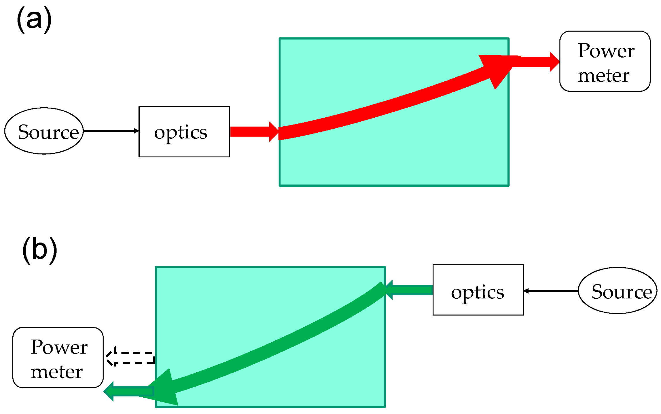
The described effect in NLC is based on the non-symmetric orientation θ of the molecular director at rest, together with the Kerr-like self-focusing response and the power-dependent birefringent walkoff of extraordinary lightwaves. The investigated phenomenon qualifies the present layout for an optical isolator as categorized by Jalas et al. [1], with the scheme in Figure 7 corresponding to Figure B2 in [1]. The extraordinary-polarized guided-wave signals transmitted along the nematicon waveguides do not interact/overlap when launched in opposite directions from the input FP port in z = 0 and from the output FP port in z = L , respectively. Such a diode, albeit nonlinear as the optical solitons and their paths are power dependent, ensures negligible crosstalk between non-simultaneous inputs due to the finite transverse extension of the guided-mode profiles as compared to the transverse separation Δ y of FP and BP trajectories in z = 0 , as computed versus input power in Figure 4 and sketched in Figure 7. Waveguided signals would also avoid the so called “dynamic reciprocity” issue addressed in [43].
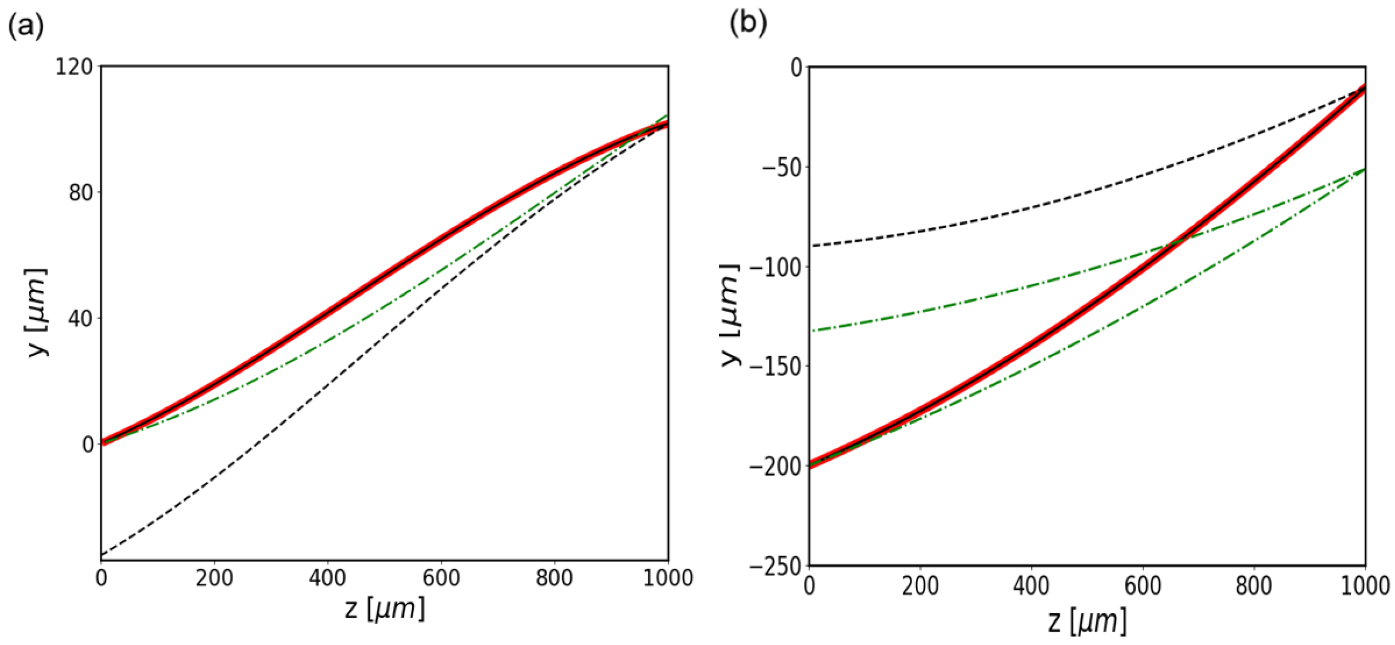
Nevertheless, while nonreciprocity in optics has been extensively discussed with reference to linear systems, it remains somewhat debated when addressing those with a nonlinear and/or dissipative response [44]. According to de Hoop’s work [45], the inherent nonlinearity entails the non-reciprocal operation of inhomogeneous non-magnetic nematic liquid crystals, which resemble dielectric stacks with a nonsymmetric scattering matrix [44,45], particularly in the geometry entailing modulation across the transverse coordinate (y). As stated in [46], inverting the sign (direction) of the input (beam/signal) wave-vector and interchanging the locations of source and detector does not leave the system transmission unchanged, enabling the attribution of nonreciprocity to these NLC samples operating as optical isolators. However, since (non)reciprocity and time (non)reversibility are commonly invoked as synonyms [44], we performed numerical experiments using a phase-conjugated reflected input beam at the output FP port y F P ( L ) , i.e., launching the BP nematicon with a beam which was the reflected replica of the FP-output after phase-conjugation. In either the y or the z modulated samples, time-reversibility is verified, as visible in Figure 8 for the two cases illustrated above. The corresponding linear response of the studied layout for identical beam inputs is also plotted in the same Figure 8, where the calculated trajectories in the diffractive regime correspond to the beams’ center-of-mass, rather than solitary waveguides’ paths.

5. Conclusions

We reported on the generation and two-dimensional evolution of counterpropagating nematicons in orientation-modulated planar cells containing undoped NLC, pinpointing their direction-dependent trajectories owing to an asymmetric propagation environment when excited from opposite sides. The studied configuration in the nonlinear regime, based on nonlocal reorientational optical spatial solitons, acts as an optical diode and appears nonreciprocal, even though it was tested to be time reversible. Counterpropagating extraordinary-wave signals naturally follow the paths established by nematicons such that the backward light leaves the sample in a location, which is well separated from the location of the forward input. We briefly addressed simple linear modulation of the optic axis orientation angle at rest, restricting the numerical analysis to one transverse dimension besides propagation. Straightforward extensions to the full (2 + 1)D model, as well as combinations of transverse and longitudinal variations in the orientation, more involved modulation laws and the simultaneous injection of oppositely-propagating beams and guided signals will be investigated and presented in forthcoming publications.

Author Contributions

Conceptualization and validation, G.A.; software, numerical investigation, E.C.; writing—original draft preparation, review and editing, G.A. and E.C. All authors have read and agreed to the published version of the manuscript.

Funding

This research was funded by the Air Force Office of Scientific Research under award no FA8655-23-1-7026. The first author’s work was supported by the Chilean Agencia Nacional de Investigacion Y Desarrollo through Beca Doctorado Extranjero 2020 (72210165).

Institutional Review Board Statement

Not applicable.

Informed Consent Statement

Not applicable.

Data Availability Statement

Not applicable.

Acknowledgments

We started this work jointly with Noel Frederick Smyth, in charge of Nonlinear Waves at the School of Mathematics, University of Edinburgh, who disappeared prematurely this year [47]. We dedicate this paper to his memory. His inspiring contributions to optical solitary waves in liquid crystals have greatly impacted the related theory.

Conflicts of Interest

The authors declare no conflict of interest.

References

  1. Jalas, D.; Petrov, A.; Eich, M.; Freude, W.; Fan, S.; Yu, Z.; Baets, R.; Popović, M.; Melloni, A.; Joannopoulos, J.D.; et al. What is—And what is not—An optical isolator. Nat. Photon. 2013, 7, 579–582. [Google Scholar] [CrossRef]
  2. Trillo, S.; Wabnitz, S. Nonlinear nonreciprocity in a coherent mismatched directional coupler. Appl. Phys. Lett. 1986, 49, 752. [Google Scholar] [CrossRef]
  3. Ferro, P.; Trillo, S.; Wabnitz, S. Demonstration of nonlinear nonreciprocity and logic operations with a twisted birefringent optical fiber. Opt. Lett. 1994, 19, 263–265. [Google Scholar] [CrossRef] [PubMed]
  4. Treviño-Palacios, C.G.; Stegeman, G.I.; Baldi, P. Spatial nonreciprocity in waveguide second-order processes. Opt. Lett. 1996, 21, 1442–1444. [Google Scholar] [CrossRef]
  5. Gallo, K.; Assanto, G. All-optical diode based on second-harmonic generation in an asymmetric waveguide. J. Opt. Soc. Am. B 1999, 16, 267–269. [Google Scholar] [CrossRef]
  6. Gallo, K.; Assanto, G.; Parameswaran, K.R.; Fejer, M.M. All-optical diode in a periodically-poled Lithium Niobate waveguide. Appl. Phys. Lett. 2001, 79, 314–316. [Google Scholar] [CrossRef]
  7. Zhou, H.; Zhou, K.F.; Hu, W.; Guo, Q.; Lan, S.; Lin, X.S.; Venu Gopal, A. All-optical diodes based on photonic crystal molecules consisting of nonlinear defect pairs. J. Appl. Phys. 2006, 99, 123111. [Google Scholar] [CrossRef]
  8. Lin, X.S.; Wu, W.Q.; Zhou, H.; Zhou, K.F.; Lan, S. Enhancement of unidirectional transmission through the coupling of nonlinear photonic crystal defects. Opt. Express 2006, 14, 2429–2439. [Google Scholar] [CrossRef]
  9. Alexander, D.; Bruce, J.; Zuhlke, C.; Koch, B.; Rudebusch, R.; Deogun, J.; Hamza, H. Demonstration of a nanoparticle-based optical diode. Opt. Lett. 2006, 31, 1957–1959. [Google Scholar] [CrossRef]
  10. Yu, Z.F.; Wang, Z.; Fan, S.H. One-way total reflection with one-dimensional magneto-optical photonic crystals. Appl. Phys. Lett. 2007, 90, 121133. [Google Scholar] [CrossRef]
  11. Amemiya, T.; Shimizu, H.; Yokoyama, M.; Hai, P.N.; Tanaka, M.; Nakano, Y. 1.54 μm TM-mode waveguide optical isolator based on the nonreciprocal-loss phenomenon: Device design to reduce insertion loss. Appl. Opt. 2007, 46, 5784–5791. [Google Scholar] [CrossRef] [PubMed]
  12. Kono, N.; Kakihara, K.; Saitoh, K.; Koshiba, M. Nonreciprocal microresonators for the miniaturization of optical waveguide isolators. Opt. Express 2007, 15, 7737–7751. [Google Scholar] [CrossRef]
  13. Yazaki, Y.; Shoji, Y.; Mizumoto, T. Demonstration of interferometric waveguide optical isolator with a unidirectional magnetic field. Jpn. J. Appl. Phys. 2007, 46, 5460–5464. [Google Scholar] [CrossRef]
  14. Lin, X.-S.; Yan, J.-H.; Wu, L.-J.; Lan, S. High transmission contrast for single resonator based all-optical diodes with pump-assisting. Opt. Express 2008, 16, 20949–20954. [Google Scholar] [CrossRef] [PubMed]
  15. Alberucci, A.; Assanto, G. All-optical isolation by directional coupling. Opt. Lett. 2008, 36, 1641–1643. [Google Scholar] [CrossRef] [PubMed]
  16. Yu, Z.; Fan, S. Complete optical isolation created by indirect interband photonic transitions. Nat. Photon. 2009, 3, 91–94. [Google Scholar] [CrossRef]
  17. Miroshnichenko, A.E.; Brasselet, E.; Kivshar, Y.S. Reversible optical nonreciprocity in periodic structures with liquid crystals. Appl. Phys. Lett. 2010, 96, 063302. [Google Scholar] [CrossRef]
  18. Zhukovsky, S.V.; Smirnov, A.G. All-optical diode action in asymmetric nonlinear photonic multilayers with perfect transmission resonances. Phys. Rev. A 2011, 83, 023818. [Google Scholar] [CrossRef]
  19. Lira, H.; Yu, Z.; Fan, S.; Lipson, M. Electrically driven nonreciprocity induced by interband photonic transition on a silicon chip. Phys. Rev. Lett. 2012, 109, 033901. [Google Scholar] [CrossRef] [PubMed]
  20. Fan, L.; Varghese, L.T.; Wang, J.; Xuan, Y.; Weiner, A.M.; Qi, M. Silicon optical diode with 40 dB nonreciprocal transmission. Opt. Lett. 2013, 38, 1259–1261. [Google Scholar] [CrossRef]
  21. Wang, D.W.; Zhou, H.T.; Guo, M.J.; Zhang, J.X.; Evers, J.; Zhu, S.Y. Optical diode made from a moving photonic crystal. Phys. Rev. Lett. 2013, 110, 093901. [Google Scholar] [CrossRef] [PubMed]
  22. Anand, B.; Podila, R.; Lingam, K.; Krishnan, S.R.; Siva Sankara Sai, S.; Philip, R.; Rao, A.M. Optical diode action from axially asymmetric nonlinearity in an all-carbon solid-state device. Nano. Lett. 2013, 13, 5771–5776. [Google Scholar] [CrossRef] [PubMed]
  23. Sounas, D.L.; Alu, A. Angular-momentum-biased nanorings to realize magnetic-free integrated optical isolation. ACS Photon. 2014, 1, 198–204. [Google Scholar] [CrossRef]
  24. Sounas, D.L.; Alu, A. Non-reciprocal photonics based on time modulation. Nat. Photon. 2017, 11, 774–783. [Google Scholar] [CrossRef]
  25. Sounas, D.L.; Soric, J.; Alu, A. Broadband passive isolators based on coupled nonlinear resonances. Nat. Electron. 2018, 1, 113–119. [Google Scholar] [CrossRef]
  26. Kittlaus, E.A.; Jones, W.M.; Rakich, P.T. Otterstrom, N.T.; Muller, R.E.; Rais-Zadeh, M. Electrically driven acousto-optics and broadband non-reciprocity in silicon photonics. Nat. Photon. 2020, 15, 43–52. [Google Scholar] [CrossRef]
  27. Yu, M.; Cheng, R.; Reimer, C.; He, L.; Luke, K.; Puma, E.; Shao, L.; Shams-Ansari, A.; Ren, X.; Grant, H.R.; et al. Integrated electro-optic isolator on thin-film lithium niobate. Nat. Photon. 2023, 17, 666–671. [Google Scholar] [CrossRef]
  28. Lepri, S.; Casati, G. Asymmetric wave propagation in nonlinear systems. Phys. Rev. Lett. 2011, 106, 164101. [Google Scholar] [CrossRef] [PubMed]
  29. Calisto, E.; Smyth, N.F.; Assanto, G. Optical isolation via direction-dependent soliton routing in birefringent soft-matter. Opt. Lett. 2022, 47, 459564. [Google Scholar] [CrossRef]
  30. Peccianti, M.; Assanto, G. Nematicons. Phys. Rep. 2012, 516, 147–208. [Google Scholar] [CrossRef]
  31. Assanto, G. Nematicons: Reorientational solitons from optics to photonics. Liq. Cryst. Rev. 2018, 6, 170–194. [Google Scholar] [CrossRef]
  32. Assanto, G.; Smyth, N.F. Self-confined light waves in nematic liquid crystals. Phys. D 2020, 402, 132182. [Google Scholar] [CrossRef]
  33. Peccianti, M.; Fratalocchi, A.; Assanto, G. Transverse dynamics of Nematicons. Opt. Express 2004, 12, 6524–6529. [Google Scholar] [CrossRef] [PubMed]
  34. Khoo, I.C. Nonlinear optics of liquid crystalline materials. Phys. Rep. 2009, 471, 221–267. [Google Scholar] [CrossRef]
  35. Conti, C.; Peccianti, M.; Assanto, G. Route to nonlocality and observation of accessible solitons. Phys. Rev. Lett. 2003, 91, 073901. [Google Scholar] [CrossRef] [PubMed]
  36. Conti, C.; Peccianti, M.; Assanto, G. Observation of optical spatial solitons in a highly nonlocal medium. Phys. Rev. Lett. 2004, 92, 113902. [Google Scholar] [CrossRef]
  37. Alberucci, A.; Assanto, G. Nematicons beyond the perturbative regime. Opt. Lett. 2010, 35, 2520–2522. [Google Scholar] [CrossRef]
  38. MacNeil, J.M.L.; Smyth, N.F.; Assanto, G. Exact and approximate solutions for optical solitary waves in nematic liquid crystals. Phys. D 2014, 284, 1–15. [Google Scholar] [CrossRef]
  39. Piccardi, A.; Alberucci, A.; Assanto, G. Soliton self deflection via power-dependent walk-off. Appl. Phys. Lett. 2010, 96, 061105. [Google Scholar] [CrossRef]
  40. Oswald, P.; Pieranski, P. Nematic and Cholesteric Liquid Crystals, 1st ed.; Taylor and Francis: Oxfordshire, UK, 2005. [Google Scholar]
  41. Laudyn, U.; Kwasny, M.; Sala, F.; Karpierz, M.; Smyth, N.F.; Assanto, G. Curved solitons subject to transverse acceleration in reorientational soft matter. Sci. Rep. 2017, 7, 12385. [Google Scholar] [CrossRef] [PubMed]
  42. Alberucci, A.; Piccardi, A.; Peccianti, M.; Kaczmarek, M.; Assanto, G. Propagation of spatial optical solitons in a dielectric with adjustable nonlinearity. Phys. Rev. A 2010, 82, 023806. [Google Scholar] [CrossRef]
  43. Shi, Y.; Yu, Z.; Fan, S. Limitations of nonlinear optical isolators due to dynamic reciprocity. Nat. Photon. 2015, 9, 388–392. [Google Scholar] [CrossRef]
  44. Potton, R.J. Reciprocity in optics. Rep. Progr. Phys. 2004, 67, 717–754. [Google Scholar] [CrossRef]
  45. De Hoop, A.T. Reciprocity of the electromagnetic field. Appl. Sci. Res. 1959, 8, 135. [Google Scholar] [CrossRef]
  46. Born, M.; Wolf, E. Principles of Optics, 7th ed.; Cambridge University Press: Cambridge, UK, 1999. [Google Scholar]
  47. Available online: https://www.alumni.caltech.edu/in-memoriam/noel-frederick-smyth (accessed on 19 March 2023).
Figure 1. Artistic rendering of a nematicon-based optical diode. The FP soliton and associated waveguide do not overlap with the BP soliton and associated waveguide, effectively isolating the FP input port from the BP light. The FP nematicon and signal are transmitted (red arrows), left bottom panel, the BP nematicon and signal are not transmitted through the FP input port, right bottom panel.
Photonics 10 01144 g001
Figure 2. Sketch of planar NLC cells of length L and width d, with linearly varying orientation angle θ of the optic axis n (green ellipses) along one of the coordinates. The red arrow indicates the input of the forward-propagating (FP) beam, and the green arrow refers to the backwards-propagating (BP) beam, with FP and BP wavepackets linearly polarized extraordinary waves. (a) Linear transverse modulation across y; θ b o t is the orientation in y = y b o t , θ t o p is the orientation in y = y t o p , with d = y t o p y b o t the width of the cell. (b) Linear longitudinal modulation of the background orientation; θ 0 is the orientation in z = 0 , θ L is the orientation in z = L .
Photonics 10 01144 g002
Figure 3. (a) Linear longitudinal modulation of the background orientation from θ 0 = 15 ° to θ L = 55 ° . (a) Extraordinary-wave refractive index n e ( z ) (black line) and birefringent walk-off angle δ ( z ) (blue dashed line) versus z in a 1 mm -long planar cell filled with E7. (b) 3D trajectories and transverse profiles of FP (green arrow) and BP (red arrow) nematicons (normalized field amplitude u in arbitrary units); input (black lines) and output (red lines) beam profiles in z = 0 , z = L are also projected on the y axis in z = 0 .
Photonics 10 01144 g003
Figure 4. Beam power dependence of transverse separation Δ y for linear longitudinal modulation (blue line with calculated data points) and linear transverse modulation (red line with calculated datapoints) in the same intervals of θ as in Figure 3 above and Figure 5 below, respectively.
Photonics 10 01144 g004
Figure 5. (a) Linear transverse modulation of background orientation in a 600 μ m wide sample from θ b o t = 30 ° to θ t o p = 50 ° . (a) Extraordinary-wave refractive index n e ( y ) (black line) and walk-off angle δ ( y ) (blue dashes) in a cell filled with E7. (b) 3D trajectories and transverse profiles of FP (green arrow) and BP (red arrow) nematicons, as in Figure 3b; input (black lines) and output (red lines) beam profiles in z = 0 , z = L are also projected on the y axis in z = 0 . Here, θ ( z = 0 ) = 33 ° for the FP input, θ ( z = L ) = 39 . 7 ° for the BP input.
Photonics 10 01144 g005
Figure 6. Comparison of nematicon trajectories for FP (solid lines) and BP (dashed lines) beams in the lossless limit (blue lines) and in the presence of typical propagation losses of 5 cm 1 (red lines): (a) linear longitudinal modulation from θ 0 = 15 ° to θ L = 55 ° ; (b) linear transverse modulation from θ b o t = 30 ° to θ t o p = 50 ° .
Photonics 10 01144 g006
Figure 7. Isolator operation: (a) FP nematicon and guided-wave copolarized signal travel from left to right, reaching the light meter; (b) BP nematicon and copolarized guided signal travel from right to left using the same FP output port, but do not reach the detector, as they follow the green path despite the identical beam excitation with k F P = k B P .
Photonics 10 01144 g007
Figure 8. Trajectories of FP and BP beams in the nonlinear case (black dashes), in the linear limit with no reorientational self-focusing (dash-dotted green lines) and phase-conjugated reflection of FP output into BP input (red lines). (a) Linear longitudinal modulation from θ 0 = 15 ° to θ L = 55 ° ; (b) linear transverse modulation from θ b o t = 30 ° to θ t o p = 50 ° .
Photonics 10 01144 g008
Disclaimer/Publisher’s Note: The statements, opinions and data contained in all publications are solely those of the individual author(s) and contributor(s) and not of MDPI and/or the editor(s). MDPI and/or the editor(s) disclaim responsibility for any injury to people or property resulting from any ideas, methods, instructions or products referred to in the content.