Review

Microwave Photonic Filters and Applications

1
Wuhan National Laboratory for Optoelectronics, Huazhong University of Science and Technology, Wuhan 430074, China
2
Optics Valley Laboratory, Wuhan 430074, China
*
Author to whom correspondence should be addressed.
Photonics 2023, 10(10), 1110; https://doi.org/10.3390/photonics10101110
Submission received: 29 August 2023 / Revised: 25 September 2023 / Accepted: 26 September 2023 / Published: 30 September 2023

Abstract

:
Microwave photonics is a promising and rapidly developing interdisciplinary field. It combines microwave and photonic techniques to generate, transmit, process, and manipulate microwave signals by using the advantages of broadband, high frequency, and low loss provided by photonics. As an important branch of microwave photonics, the microwave photonic filter (MPF) can overcome the limitations set by traditional electronic technology and can realize advanced signal processing in modern communication systems due to its higher performance, selectivity, and flexibility. This review provides a comprehensive overview of MPFs, including fundamental principles, typical structures, and key applications. Additionally, the microwave photonic integration is a very important tendence because of its advantages of small size, light weight, low power consumption, and low cost. The recent advances in integrated MPF are also reviewed.

1. Introduction

Microwave photonics (MWP) is an interdisciplinary field that integrates traditional microwave technology with photonic technology [1]. It takes advantage of the broadband, high frequency, and low loss offered by modern photonics to generate, transmit, process, and manipulate microwave signals [2]. Initially focused on defense applications [3], MWP has been extended to address a considerable number of civil applications, including cellular [4], wireless and satellite communications [5], distributed antenna systems [6], and high-resolution optical sensing [7]. The schematic diagram of a typical microwave photonic link is shown in Figure 1 [8]. In the microwave photonic link, we can see that microwave signals are loaded onto the optical carrier by an electro-optical modulator at first. Then, the microwave photonic signals are transmitted and processed by optical devices. Thanks to the ultra-low transmission loss of optical fiber, the microwave photonic signals can be transmitted over a long distance. Meanwhile, compared with electrical devices, the bandwidth of optical devices is much larger, which enables the direct processing of broadband high-frequency microwave signals in the optical domain. Before output, the microwave photonic signals are converted back to electrical signals by using a photodetector (PD). Compared with traditional microwave technology, the major difference of microwave photonic technology is that the microwave signals are processed in the optical domain, which can take the advantages of photonic technology [2], including ultra-low loss, large bandwidth, and high immunity, to electromagnetic interference.
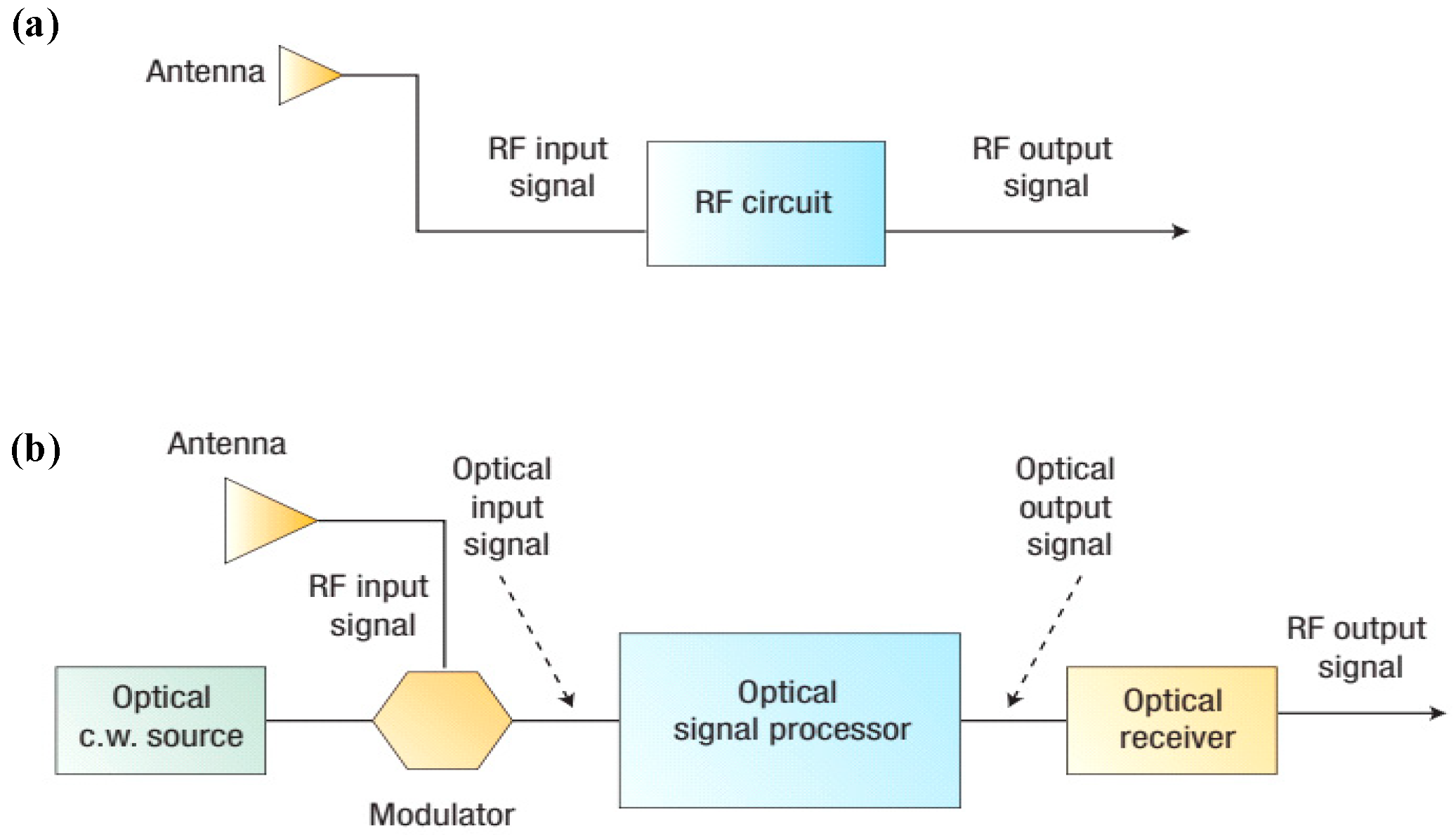
In MPFs, optical devices are used to achieve filtering functions in the microwave frequency band. A comparison of a traditional electronic filter and an MPF is shown in Figure 2 [8]. In the traditional microwave filter, the radio frequency (RF) signal received by the RF antenna is processed in the RF circuit to perform the signal processing task. While, in the MPF, the RF signal received by the RF antenna is firstly modulated onto the optical carrier by an optical modulator, and the RF signal is converted to an optical signal. Then, the optical signal is processed by the optical signal processor. Before output, the optical signal is converted back to the RF signal by the optical receiver. Different from traditional electronic filters, the RF signal is processed by optical devices in the optical domain, and broadband RF signals at high frequency can be directly processed because of the large bandwidth. MPF also shows high tunability [9,10,11] and reconfigurability [12]. This means that the center frequency can be widely tuned, and the bandwidth can be changed to adapt to different applications [13]. Even the frequency response of the MPF can be switched between bandpass and bandstop shapes [14,15]. At the same time, optical signals transmitted in optical fibers or optical waveguides show strong immunity to electromagnetic interference [16,17]. MPF plays an important role in the field of microwave photonics. For example, optical oscillators (OEOs) benefit from MPF to achieve broadband tunability and low phase noise [18,19,20,21,22,23]. The measured accuracy and bandwidth are also improved in microwave frequency measurements through integrated photonic technology [24,25]. Programmable MPF achieves real-time signal processing and facilitates the development of reconfigurable systems [26,27,28,29]. MPF has shown great potential in modern communication systems.
In this review, the first part introduces the theoretical foundation and the classification of MPF. The theoretical part paves the way for the design of MPF. The second part introduces the applications of MPF in various areas, including optoelectronic oscillators and microwave frequency measurements. Since the integrated MWP (IMWP) shows superiorities in size, weight, power consumption, and cost, the third part introduces the integrated MPFs and applications in integrated systems.

2. Fundamental Concepts

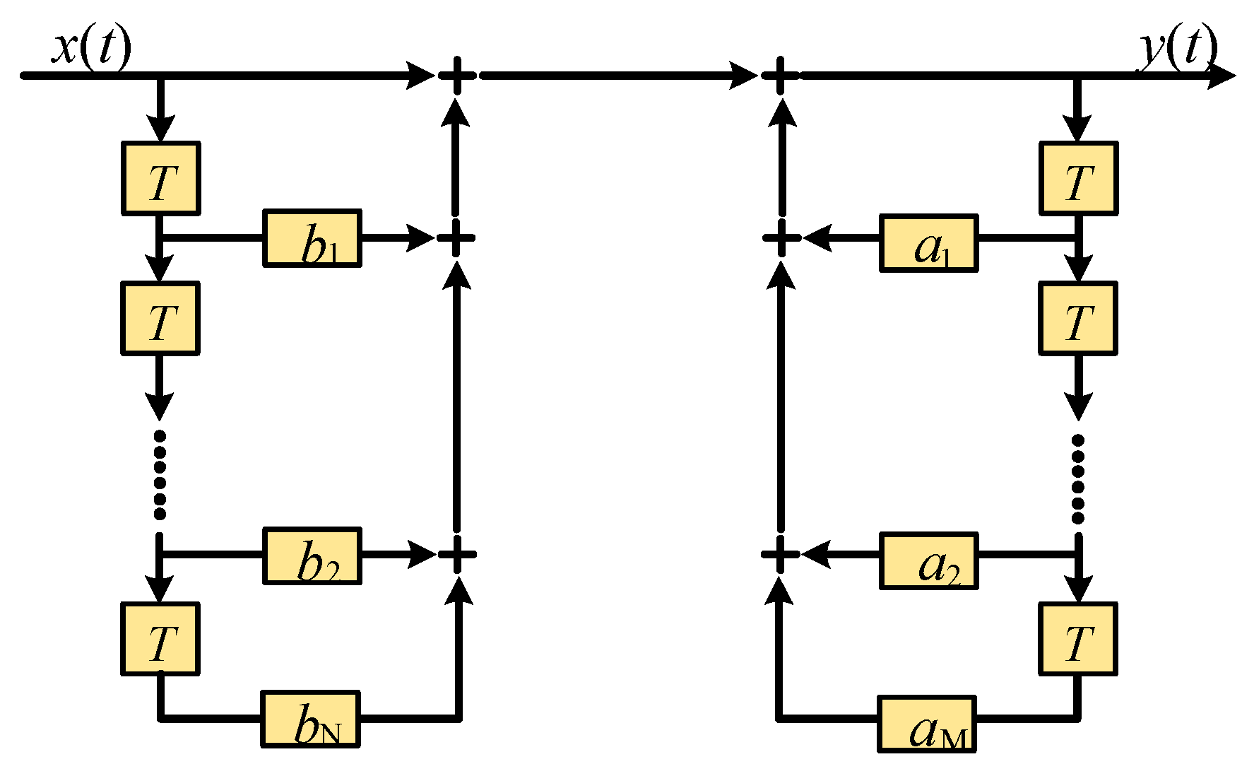
Although there are differences between the MPF and the traditional electronic filter in processing microwave signals, their system descriptions are identical, as shown in Figure 3. The input signal x(t) is divided into N parts to generate N taps. The N taps are introduced in turn with a series of delays of T, 2T … (N − 1)T and a series of amplitude weightings of b1, b2bN, respectively. Finally, all taps are summed and output to the system. Additionally, the output signal y(t) can be fed back into the system after delaying, weighting, and summing [30]. In the MPF, the functions of splitting, delaying, weighting, and summing can be implemented by using different optical components. For example, the tap sampling can be realized by splitting a single source into N outputs using a 1 × N coupler or a wavelength division multiplexing (WDM) light source [31,32]. The addition unit can be realized by using optical couplers [9,33] or WDM combiners [34,35], the multiplication unit can be realized by using optical attenuators [36,37] or optical amplifiers [33,38], and the delay unit can be realized by using optical fibers [35,39], high Q resonant cavities [40,41,42], or fiber Bragg gratings (FBGs) [43,44,45].
The relationship between the output and the input signals can be expressed as follows:
n = 0 N b n x ( t n T ) + m = 0 M a m y ( t m T ) = y ( t )
The discrete Fourier transform of Equation (1) yields the transfer function expression of the MPF as follows:
H ( ω ) = n = 0 N b n e j ω n T 1 m = 0 M a m e j ω m T
when am = 0, the transfer function of the filter can be obtained according to Equation (2), and can be expressed as follows:
H ( ω ) = n = 0 N b n e j ω n T
In this case, the filter is called the finite impulse response (FIR) filter because the number of taps is finite. However, when am ≠ 0, the filter is called the infinite impulse response (IIR) filter because the tap number is infinite in theory. From Equation (2), it can be seen that the frequency response of the filter is a periodic function, and the period is T.

2.1. Parameters of the MPF

The MPF is a versatile RF signal processing system utilized in a wide range of applications, and different transmission spectra are required in different scenarios. The subsequent discussion presents the pertinent parameters used to assess the performance of the MPF.
The response of a typical FIR-MPF is shown in Figure 4.
(1)
Free spectral range
Free spectral range (FSR) refers to the spectral period of the frequency response. It is determined by the unit time delay T, which is given by 1/T. For some applications, a single-pass band filter in the entire operating range is required. Therefore, the FSR should be larger than the operating range, and a small delay is required for a large FSR. However, the minimum FSR is limited by the coherence of the optical source of the MPF and environmental influences.
(2)
Full width at half maximum bandwidth
In Figure 4, the full width at half maximum (FWHM) bandwidth is denoted as ∆fFWHM, which refers to the bandwidth when the output power decreases by half from the maximum value. When logarithmic coordinates are used, it is the bandwidth corresponding to a 3-dB drop in magnitude. Therefore, the FWHM bandwidth of the filter passband can also be called the 3-dB bandwidth, which characterizes the spectral width that can be selected by the filter. The FWHM bandwidth of the MPF is mainly determined by the number of taps. When more taps are generated and summed, the quality factor of the MPF is increased, and the FWHM bandwidth is reduced correspondingly.
(3)
Quality factor
The quality factor (Q) is defined as the ratio of FSR to 3-dB bandwidth. It is a parameter to measure the superiority of filter frequency selectivity, and a larger value corresponds to a better filtering selectivity. For the FIR-MPF, Q is closely related to the number of taps N. When the number of taps satisfies N > 10, it can be concluded that Q ≈ N [16]. For the IIR-MPF, Q is mainly related to the loss in the optical loop. A lower loop loss corresponds to a higher Q value.
(4)
Rejection ratio
The rejection ratio is defined as the ratio of the magnitude of the passband to the magnitude of the secondary sidelobe. It describes the suppression degree of out-of-passband signals for the MPF. A larger the rejection ratio indicates that the out-of-band signals are suppressed lower. The rejection ratio of the MPF is also related to the number of taps and the tap coefficients of the MPF.
(5)
Shape factor
The shape factor is defined as the ratio of stopband bandwidth, such as the 20-dB bandwidth to the 3-dB bandwidth. It characterizes the transition edge steepness of the filter passband. The more the shape factor tends to be 1, the more the filter tends to be an ideal rectangular filter.
(6)
Tunability and reconfigurability
The tunability describes to what extent the center frequency of the filter can be tuned. The reconfigurability describes to what extent the filter shape can be changed, such as switching the filter response between bandpass and bandstop responses or adjusting the bandwidth. Both tunability and reconfigurability can be achieved by manipulating the parameters according to Equation (2). For example, the tunability can be achieved by adjusting the phase terms to the weighting complex coefficients. In contrast, changing the magnitudes of the weighting coefficients or the number of taps can change the filter shape, thus achieving reconfigurability.

2.2. Classifications of the MPF

According to the frequency response, the MPF can be classified into different types. In this section, the classifications of the MPF according to different criteria are introduced.

2.2.1. FIR- and IIR-MPFs

According to the number of taps, MPF can be classified into FIR- and IIR-MPFs.
When am = 0, only a finite number of taps are summed. Therefore, the corresponding MPF is defined as FIR-MPF. The FIR-MPF is advantageous in reconfigurability, because the coefficient of each tap can be conveniently adjusted. To demonstrate the FIR-MPF, a laser diode (LD) with a single wavelength and a pair of optical couplers are used, as shown in Figure 5a [46]. The modulated optical signal is divided into N paths by the 1 × N coupler. Then, different weightings and delays are applied to the N taps, and finally, they are combined by the N × 1 coupler and converted back to an electrical signal by the detector. Meanwhile, FBGs can reflect the wavelengths that satisfy the Bragg condition and are usually used to obtain finite taps of the MPF, as shown in Figure 5b. The FBGs with different reflection wavelengths are uniformly arranged to reflect different wavelengths of the optical source, generating different taps of the MPF. The coefficient of each tap can be controlled by designing the reflectivity of FBG. Then, the weighted taps experience different time delays and are summed in the PD. Finally, an FIR-MPF is achieved [43,44,45].
The schemes mentioned above are realized based on uniform time delay. Reference [47] uses an array of lasers as the taps of the filter and introduces additional time delays at different taps, resulting in a nonuniformly spaced FIR-MPF. An arbitrary bandpass frequency response with all-positive tap coefficients is obtained. When nonuniformly spaced wavelengths are passing through a dispersive fiber, there will be nonuniform time delays between adjacent taps. The nonuniform time delays provide equivalent phase shifts to the tap coefficients, thus achieving an MPF with arbitrary response shape. Further, the nonuniformly spaced FIR-MPF has been proposed to realize a microwave bandpass differentiator [48]. Compared with the differentiator based on previous negative coefficient MPFs, the complexity of the proposed differentiator based on nonuniformly spaced MPF is reduced.
When am ≠ 0, the output signal is fed back to the input port. Consequently, the number of taps is infinite, and the corresponding MPF is defined as IIR-MPF. Figure 6a shows a typical diagram of the IIR-MPF [46]. It can be seen that the number of generated taps tends to be infinite due to the recirculating loop. In IIR-MPF, the frequency response is dependent on the coupling coefficient of the coupler, the loop loss, and the loop length [49]. Since the loop length is fixed and no microwave phase shifter is used in the loop, the corresponding frequency response of the MPF cannot be tuned. Using a tunable delay line can definitely achieve a tunable frequency response, as shown in Figure 6b [50]. However, the FSR of the MPF can be correspondingly changed.
Compared with FIR-MPF, IIR-MPF uses fewer components but obtains higher-Q factors [51,52,53]. Compared with a single IIR-MPF, using the cascading method can significantly enhance the FSR and the Q factor of the MPF. Reference [54] presents two cascaded active recirculating delay line (RDL) loops with a semiconductor optical amplifier (SOA) inserted between the two loops, as shown in Figure 7a. Each active RDL loop acts as a single IIR filter. To eliminate the optical interference caused by cascading two IIR loops [55] and to obtain a stable response, cross-gain modulation (XGM) in the SOA is used to perform wavelength conversion. By doing so, the FSR and Q factor are significantly improved using the Vernier effect technique.
Notably, MPFs can be applied to an instantaneous frequency measurement (IFM). Traditionally, the IFM is performed in the electrical domain, faces challenges in recognizing high-frequency microwave signals, and is susceptible to electromagnetic interference. Microwave photonic techniques have been proposed to solve these problems [6,56,57]. For example, an optical channelizer [58,59,60] can be used to measure microwave frequencies. However, specially designed diffraction gratings and PD arrays are required, which makes the system bulky and costly. In addition, the measurement accuracy is usually low because of the wavelength spacing drift and relative power fluctuations of multiple laser sources. The IFM can also be realized based on frequency to time mapping [61,62,63], which shows the advantage of measuring multiple frequencies simultaneously. To enhance frequency resolution, an IIR-MPF and an FIR-MPF are combined to realize IFM, as shown in Figure 8a [64]. A monotonic frequency response ranging from positive to negative infinity is obtained, and a unique relationship between the output response and the input microwave frequency is established. Based on the calculation, the minimum resolution is 2.67 dB/GHz for a 10 GHz measurement range. Therefore, the microwave frequency measurement resolution is significantly improved, and the complexity of the system is reduced.
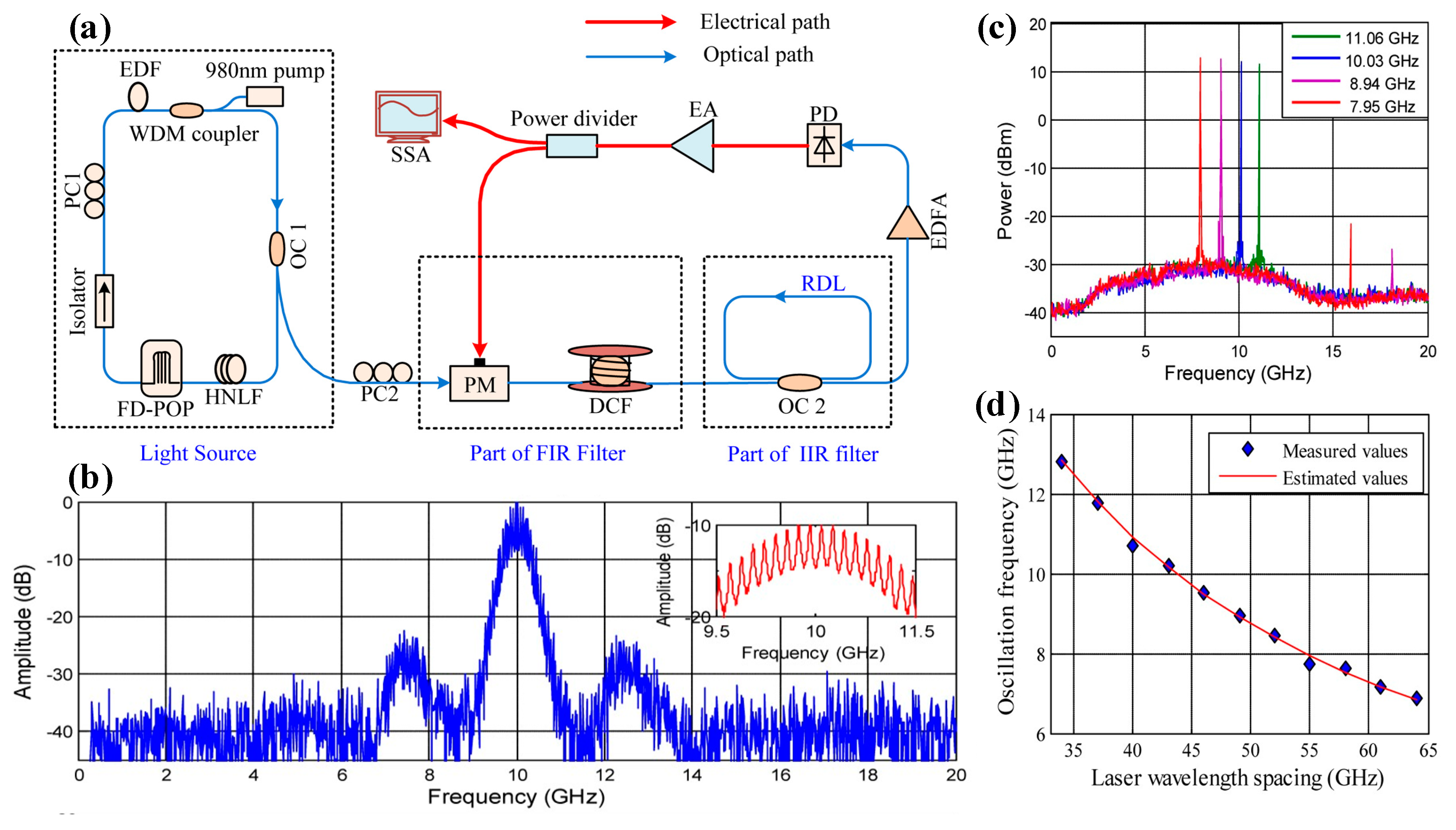
Additionally, MPFs can also be applied to OEO, which is an ideal solution for generating high-frequency microwave signals with low phase noise and broadband tunability [65,66]. In the OEO, using a long optical fiber is a common approach to promoting the quality factor of the loop, thus reducing the phase noise. However, a long fiber loop results in ultra-narrow eigenmode frequency spacing. Therefore, an ultra-narrow electrical bandpass filter (EBF) is required for single-mode oscillation [67,68]. The problem is that the ultra-narrowband EBF is usually difficult to tune over a broad band [69,70]. By contrast, MPFs can be widely tuned and thus provide a promising solution to realizing tunable OEOs. Reference [18] proposes a tunable bandpass MPF that successfully replaces the narrow EBF in a traditional single-loop OEO. The MPF was realized by cascading an FIR filter and an IIR filter, as shown in Figure 9a. The FIR filter is realized based on tunable multi-wavelength lasers and a dispersion-compensated fiber (DCF). The IIR filter is realized simply based on a passive RDL loop. By adjusting the wavelength spacing of the multi-wavelength laser, the center frequency of the MPF passband can be tuned, which determines the frequency of the generated microwave signal. As a result, tunability of the OEO can be achieved over a wide frequency range without sacrificing the quality of the produced signal. Thus, a wide oscillation frequency tuning range of 6.88–12.79 GHz is realized.

2.2.2. Positive, Negative and Complex Coefficient MPF

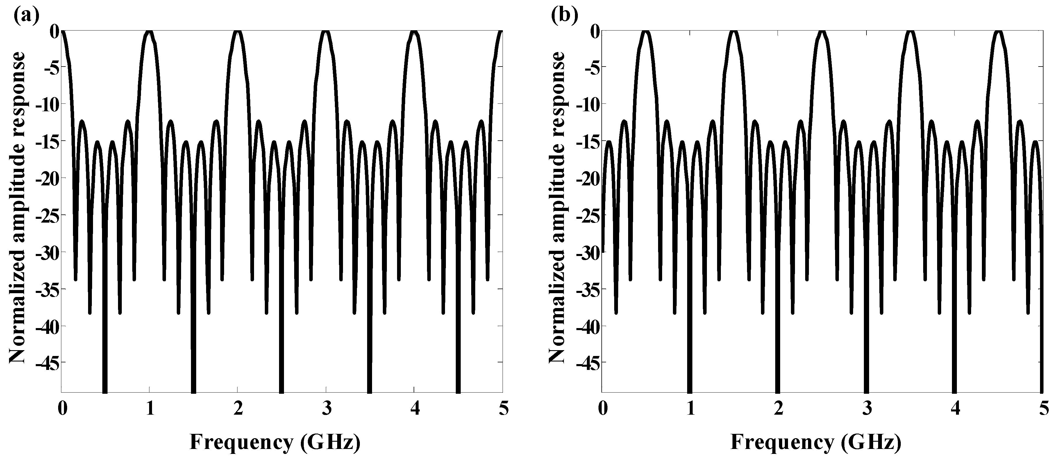
When am > 0 and bn > 0, which indicate that all the coefficients of the MPF are positive, the corresponding MPF is defined as a positive coefficient MPF. The coefficient weighting is usually achieved by using an optical amplifier or attenuator. Since the light power cannot be negative, only positive coefficient MPFs are achieved. However, positive coefficient MPFs always exhibit low-pass transmission and make it impossible to implement some specific response shapes, such as the rectangular filter [71]. On the other hand, positive coefficient MPFs always have a passband at zero frequency, which should be avoided in some application scenarios [72]. When the negative weighting coefficient is obtained, the filter is called the negative coefficient MPF, and the passband at zero frequency can be eliminated by properly setting the positive and negative coefficients [71], as shown in Figure 10. There are several methods that have been proposed to achieve negative coefficient MPFs. The first method is to use differential detection, which means that the taps are divided into two parts, and then, subtraction detection is performed in a microwave hybrid [32,73]. The second method is to use the XGM effect in which the pump light power and probe light power are complementary [74,75,76,77,78]. The third method is to set a pair of Mach–Zehnder modulators (MZMs) at in-phase and counter-phase modulation points, respectively. Therefore, the phase difference between two intensity modulated signals is π, thus achieving negative coefficient taps [79].
Using nonlinear effects in SOA [80,81,82], such as XGM [74,75,76,77,78] and four-wave mixing (FWM) [83], a series of MPFs can be realized. Figure 11a shows a negative coefficient MPF achieved by using XGM in SOA. After XGM, the probe light is counter phase modulated by the pump light, and a negative coefficient is obtained [75,84]. The signal light at wavelength λ1 is modulated and divided into two paths. One is delayed and another is input into the SOA together with the probe light at wavelength λ2. Due to the XGM effect, the signal at λ1 is copied to the probe light at λ2 in inverted phase. Therefore, a negative coefficient tap is obtained. Meanwhile, reference [85] has proposed a bandpass MPF with high-frequency selectivity based on XGM in SOA. As shown in Figure 11b, the intensity modulated signal by MZM is injected into the RDL loop after the power adjusted by EDFA and the attenuator. After XGM, the amplified spontaneous emission (ASE) spectrum of the SOA is modulated by the intensity modulated optical signal, and negative coefficients are obtained. Then, the converted ASE spectrum circulates in the RDL loop and achieves a high-Q factor frequency response after PD. The residual pump signal, unfiltered by the tunable narrowband optical filter (TNOF), realizes a weak all-pass response which can improve the shape factor.
When bn is a complex number and the phase of coefficient bn can be adjusted from 0 to 2π, the MPF is called the complex coefficient MPF, whose transfer function can be expressed as follows:
H ( ω ) = n = 0 N | b n | e j φ n e j ω n T
The biggest advantage of the complex coefficient MPF is its excellent tunability. The passband or the stopband of the complex coefficient MPF can be tuned by adjusting the phases φ n of the complex coefficients. Notably, by changing the unit time delay T, the MPF can also be tuned, but the bandwidth and FSR will be changed at the same time, which is detrimental for processing discrete signals. However, the complex coefficient MPF can be tuned, while the bandwidth and FSR remain unchanged. Notably, the complex coefficient MPFs are achieved by using microwave photonic phase shifters. Several approaches have been proposed to achieve microwave photonic phase shifters, such as using an all-optical differentiator [36], using nonlinear effects in optical devices [86,87], and using a polarization modulator (PolM) [88,89]. Based on stimulated Brillouin scattering (SBS) in optical fiber, an MPF with tunable complex coefficients is reported in reference [9]. The complex coefficients are realized by combining optical single sideband (SSB) modulation and SBS. It shows that when an optical carrier is aligned with the SBS gain spectrum, the phase of the optical carrier is shifted. After photodetection, a phase shifted microwave signal is generated [90]. However, these approaches are realized based on discrete devices and complex. By contrast, the optical all-pass filter is an ideal candidate to achieve a microwave photonic phase shifter [91,92,93]. The all-pass filter based on a microwave photonic phase shifter is quite simple and compact. A detailed introduction of the all-pass filter is given in Section 3.1.3.
Notably, a pair of MPFs with positive and negative coefficients can be applied to microwave frequency measurements [94]. A low-pass MPF with coefficients of (1, 1) and a band-pass MPF with coefficients of (−1, 1) are implemented using a PolM and two sections of polarization preserving fiber (PMF), as shown in Figure 12a. Due to the complementary frequency responses of the MPF pair, an amplitude comparison function (ACF) can be obtained. The ACF is the ratio of the two transfer functions of the MPF pair and is quasi-linearly monotonically decreasing in a large frequency band range. The measurement of the microwave frequency can be obtained by simply measuring the microwave powers from the two outputs of the MPF pair. Since the MPF pair is realized using a single wavelength, the measurement accuracy is independent of the laser wavelength, which significantly reduces the cost and complexity of the system. As shown in Figure 12c, a measurement accuracy of less than 0.2 GHz over the 36 GHz microwave frequency measurement range is finally realized.
As mentioned above, the OEO requires a narrow passband EBF for mode selection. Since the SBS has a narrow and large gain spectrum, SBS-based MPF can be adopted in OEO to replace the EBF for mode selection. A single-passband MPF with an ultra-narrow passband is realized by cascading an SBS-based MPF and an IIR-MPF based on an RDL loop [18,19,95]. The experimental setup is shown in Figure 13a, and the measured frequency response of the cascaded MPFs is shown in Figure 13b. Results show that the cascaded MPF has an ultra-narrow FWHM bandwidth of 150 kHz, while the mode spacing of the OEO is 200 kHz. Therefore, single mode oscillation can be guaranteed, and the mode hopping and side mode noise are significantly suppressed.
The application of MPF in OEOs offers several advantages. Due to the low-loss characteristics of the optical elements, the MPF achieves a high-Q factor, which enables the OEO to generate high-frequency microwave signals with low phase noise. The wide operation bandwidth and tunable center frequency of the MPF enable the OEO to generate microwave signals at different frequencies over a wide frequency range. Additionally, the MPF can also be reconfigured dynamically to enable the OEO to generate different signals [96].

2.2.3. Coherent and Incoherent MPFs

In the MPF, microwave signals are carried by an optical carrier. The schematic diagram of the MPF in Figure 5a shows that multiple taps are summed together in the detector. Notably, the coherence character of the optical carrier can significantly impact the frequency response of the MPF. According to the coherence of the optical carrier, the MPFs can be classified into coherent MPFs and incoherent MPFs.
In a coherent MPF, the unit time delay T is much smaller than the coherent time of the optical carrier τ c o h . Therefore, when all the taps are summed in PD, the converted photocurrent is proportional to the square of the summed optical field of all the taps. Therefore, the optical phases of the taps play a predominant role in the frequency response of MPF. Negative and complex coefficients of MPF can be implemented. On the other hand, since the operation of MPF depends on optical interference, the optical phase variation of any tap of the coherent MPF (e.g., delay or refractive index change due to the environmental fluctuations [46]) will change the frequency response of the MPF and cause high instability. To achieve coherent MPFs with enhanced stability, the unit time delay in the MPF should be reduced to be as small as possible. The minimized unit time delay makes the optical phase variations between the arbitrary two taps caused by environmental fluctuations to be identical to each other.
To reduce the unit time delay, phase-shifted fiber Bragg gratings (PS-FBGs) are used [97]. In reference [97], a PS-FBG is used to eliminate one sideband of the phase modulated signal. After phase modulation to intensity modulation (PM-IM) conversion, a microwave bandpass filter is obtained, as shown in Figure 14a. Instead of using a single PS-FBG in transmission, two cascaded FBGs are used in reference [98], in which a single passband is realized without phase-induced intensity noise. The schematic diagram of the coherent MPF is shown in Figure 14b. One FBG is used to select the optical carrier, and the other FBG is used to select a sideband Then, a phase modulated signal is converted to an SSB intensity modulated signal. The center frequency of the microwave bandpass filter can be tuned simply by tuning the center frequency of the notch filter or the wavelength of the laser source. The spectral shape remains constant during the tuning process.
Besides the FBG, the coherent MPF can also be realized by using integrated devices, which have a compact size and minimize optical phase variation among different taps due to environmental fluctuation. Therefore, the frequency response of the MPF tends to be stable. However, the overall impact caused by environmental fluctuations on the coherent MPF, such as the frequency response drifting, still exists. Details of the integrated MPF are presented in Section 3.
When the coherence time τ c o h is much shorter than the unit time delay T, the corresponding MPF is called incoherent MPF. The optical phase relationship between any two taps is completely random, and the optical power input into the detector is the sum of the optical power of all taps. In this scenario, the incoherent MPF exhibits little susceptibility to environmental fluctuations and shows exceptional stability [17]. However, a drawback of incoherent MPF lies in its coefficients, which are constrained to positive values, and this leads to a serious limitation of the range of transfer functions. Meanwhile, the FSR of an incoherent MPF is usually very small [72]. Fortunately, there are solutions available for the implementation of incoherent MPF with negative coefficients, as mentioned above. Reference [99] reports a technique for generating negative coefficients of incoherent MPF based on two MZMs biased at complementary transmission slopes. Two MZMs are biased in the linear region in opposite transmission slopes, as shown in Figure 15a, respectively. When microwave signals are applied to different modulators, the envelopes of the modulated optical signals are complementary. At the output of the PD, the counter phase microwave signals are generated, resulting in negative coefficients, as shown in Figure 15b.

3. Microwave Photonic Integration

Integrated optoelectronic devices based on semiconductors have a compact size and excellent reliability, and they can even achieve functions impossible to be achieved based on discrete devices. IMWP has the potential to optimize performance and reduce power, footprint, and cost in the large-capacity and bandwidth systems [100]. IMWP deals with the application of integrated photonic techniques in microwave photonic systems [101,102]. In the past few years, IMWP has become the most active area of microwave photonic research [8], with remarkable advances in integrated photonics based on various material platforms such as indium phosphide (InP), silicon on insulators (SOI), silicon nitride (Si3N4), and lithium niobate on insulators (LNOI). The SOI platform is most widely used in IMPF by the feature of COMS compatibility. Several integrated passive elements are available In SOI, such as arrayed waveguide gratings, optical filters, and Ge photodetectors. The InP platform can provide all components for monolithic integration, especially the active optical components, such as the laser diode, semiconductor optical amplifier, and mode-locked laser. The ultra-low loss of Si3N4 facilitates the manufacture and application of optical waveguides and tuning elements, such as MRR and MDR. LNOI has a high refractive index and high second-order nonlinearity, and it is widely used in modulators. In this section, the integrated MPF (IMPF) and its applications in integrated systems are reviewed. A detailed performance comparison of the reported IMPFs is presented in Table 1

3.1. IMPF

In IMPF, the unit time delay can be significantly reduced to as small as 15.4 ps [109]. Therefore, the obtained IMPF is usually coherent MPF, which shows that quite large FSR and complex coefficients can be easily obtained. In IMPF, the performance promotion and flexibility enhancement are two focused problems. Here, we review the advances in promoting the performance and flexibility.

3.1.1. Performance Enhancement

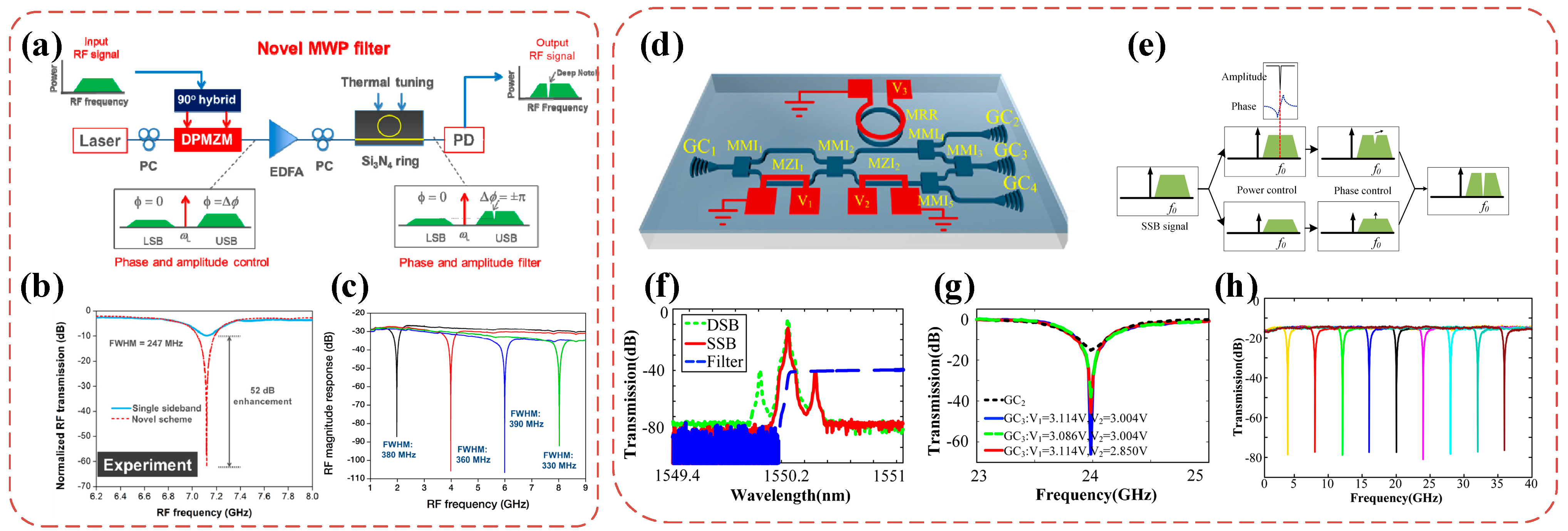
The performance of the MPF includes the rejection ratio, Q factor, shape factor, etc. Traditional FIR-MPFs based on discrete devices have periodic filter transfer functions even within a small operation bandwidth because of rather small FSRs, which block the MPF from being applied in practical RF applications because of periodic passbands in its operation bandwidth. In contrast, IMPFs are advantageous in obtaining very large FSRs, and a single passband filter in a large operation bandwidth can be obtained consequently. The microring resonator (MRR) is usually used to achieve IMPFs with a high-Q factor. However, for an all-pass MRR, there is a trade-off between the rejection ratio and the bandwidth at the output port. It is impossible to obtain the narrowest bandwidth while achieving the maximum rejection ratio. To solve this problem, a technique that optically cancels the microwave signal at the resonant wavelength of the MRR is proposed to increase the rejection ratio of the microwave photonic notch filter [110]. An EOM and a silicon nitride-based MRR are used to operate the phase and amplitude of the two optical sidebands, as shown in Figure 16a. The two sidebands corresponding to the target microwave frequency are placed with equal amplitude and opposite phase. When passing through the PD, the beating between the optical carrier and two sidebands is generated. Notably, the two beating microwave signals are of equal magnitude and opposite phase and, thus, are completely canceled. Therefore, a notch MPF with a peak rejection as high as 62 dB is obtained, as shown in Figure 16b. An improvement of 52 dB in peak rejection is obtained by this technique. The center frequency can be tuned from 1 to 9 GHz, and the peak rejection remains above 55 dB during the tuning process, as shown in Figure 16c.To reduce system complexity, reference [106] proposed and demonstrated an SOI-based widely tunable MPF with an ultra-high rejection ratio. The MPF is realized by using two cascaded tunable Mach–Zehnder Interferometers (MZIs) and an under-coupled MRR, as shown in Figure 16d. Figure 16e shows the principle of the MPF. Two cascaded tunable MZIs are used to achieve destructive interference by controlling the amplitude and phase of the two first order sidebands of the phase modulated signal. When the two first order sidebands are of equal magnitude and counter phase, a microwave photonic bandstop filter with an ultra-high rejection ratio can be obtained. Measured results show that the peak rejection is higher than 60 dB, the FWHM bandwidth is 780 MHz, and the center frequency can be tuned from 0 to 40 GHz. Another advantage of this work is that it simultaneously achieves ultra-high peak rejection and narrow bandwidth without the external electrically orthogonal hybrid coupler.
As mentioned above, the MRR is one of the most important on-chip photonic devices for realizing IMPFs due to its small size, unique amplitude and phase response, and excellent tunability [111,112,113,114]. Many IMPFs using on-chip MRRs [108,111,115,116,117,118] or microdisk resonators (MDRs) [24] have been demonstrated. Most of the MPFs based on silicon MRR exhibit a very coarse resolution in the order of GHz or tens of GHz [24,115,116,119]. This is caused by the high transmission loss due to the rough sidewall scattering of the waveguide. To reduce the bandwidth of the MPF based on MRR, the transmission loss must be reduced. Therefore, several special fabrication processes have been employed, such as thermal reflow [120,121], chemical–mechanical planarization (CMP) [122], and multiple-exposure techniques [123,124]. However, these special fabrication techniques increase complexity. Therefore, approaches that use the design of geometry of the waveguide have been proposed to reduce scattering loss, such as using an ultrathin core waveguide [125,126] and multimode ridge waveguides [127]. The intuitive idea is to reduce the interaction between the optical field confined in the optical waveguide and the rough sidewall. To ensure single-mode propagation, the multimode waveguide can be connected with a single-mode waveguide with a linear adiabatic taper [109] or designed with adiabatic propagation [128]. Figure 17a,b shows the schematic diagram and the microscope image of the fabricated ultrahigh-Q MRR, respectively. The ultrahigh-Q MRR is fabricated based on the standard SOI MPW-foundry processes [129]. The resonator is mainly composed of two multimode straight waveguides (MSWs) connected with two 180° modified Euler multimode waveguide bends (MWBs). Figure 17c shows the simulated light propagation in the Euler MWB and the mode profiles at the input and output ports. The test results show that the transmission loss of the optical waveguide is only 0.065 dB cm−1, which is 20 times smaller than that of traditional SOI strip optical waveguides. Consequently, an intrinsic Q-factor up to 1.02 × 10⁷ is demonstrated for the first time based on the standard 220-nm-SOI MPW-foundry processes. Further, a tunable MPF with an FWHM bandwidth of 20.6 MHz and a tuning range of about 20 GHz is realized based on the ultra-high-Q MRR, as shown in Figure 17e,f, respectively.
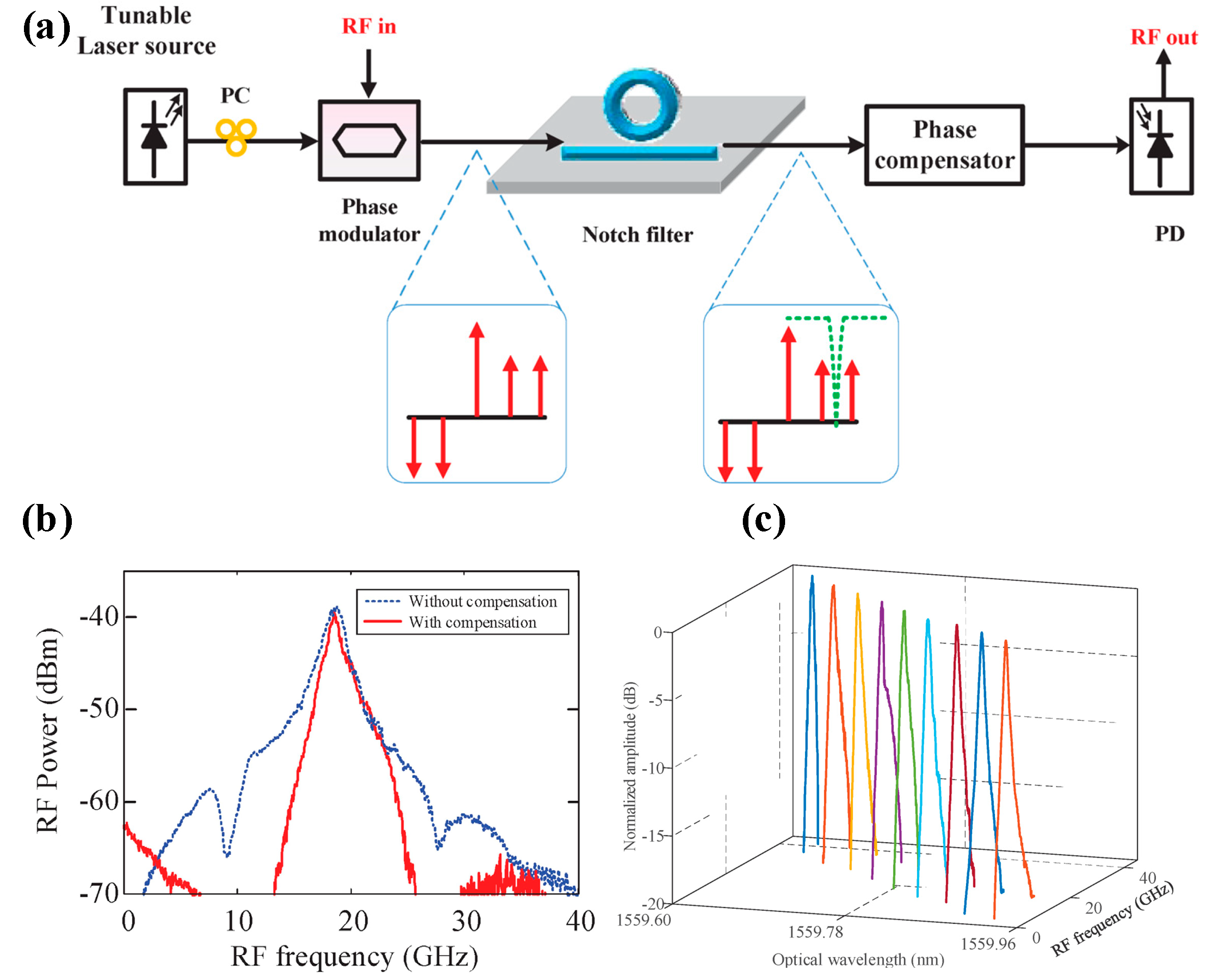
Using PM-IM conversion, it is very convenient to achieve a microwave bandpass filter. However, the optical phase of the MRR-based notch filter can also affect the frequency response of the MPF. This is because the detected RF power can be affected by the phase variation of the two sidebands. To solve this problem, it is proposed to use a phase compensator before the PD to overcome the RF distortion induced by the unwanted phase variation [130], as shown in Figure 18a. The measured MPF response is illustrated in Figure 18b. It can be noted that the FWHM bandwidth is only 1.05 GHz, which is 0.8 GHz narrower than the FWHM bandwidth of the MPF without phase compensation.
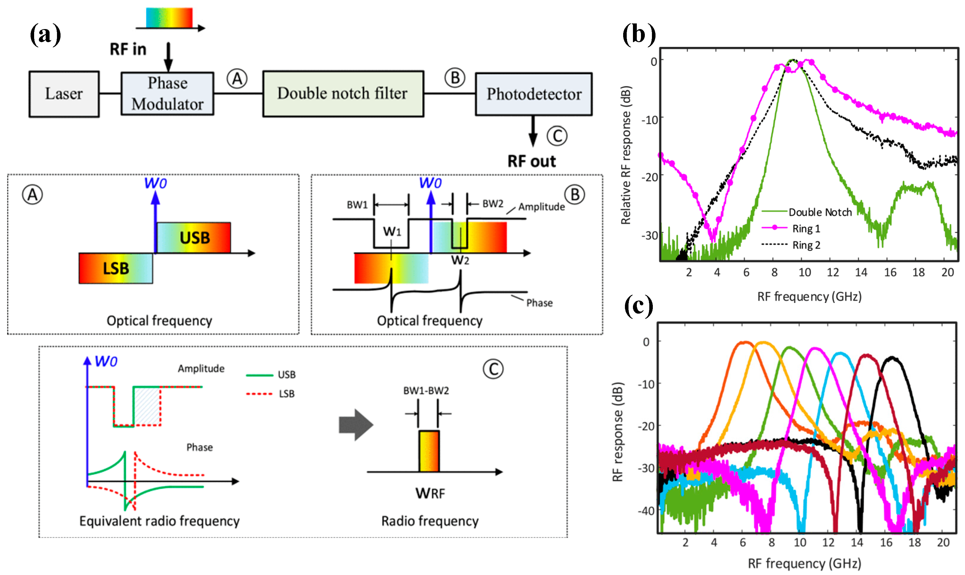
PM-IM conversion is used to realize that single-passband MPF is effective and works well. The premise is that optical notch filters do not introduce an additional phase outside the notch region. In practice, however, the additional non-zero phase introduced by the filter outside its notch band prevents the complete elimination of microwave interference out of the passband of MPF, resulting in a significant reduction of the rejection ratio of the MPF and the shape factor. In reference [116], a tunable single passband MPF is realized with an improved shape factor and rejection ratio. Figure 19a shows the schematic diagram and illustration of the proposed single passband MPF, which is realized by using an optical double-notch based on two cascaded MRRs. By slightly changing the FSRs of the two MRRs, two optical notches with slightly different bandwidths and center frequencies can be obtained. By locating the optical carrier in the middle of the two microring notch filters, the additional phase introduced by each filter outside the notch regions is effectively eliminated. Meanwhile, the shape factor and the rejection ratio of the single passband MPF are also improved, as shown in Figure 19b. In addition, the bandwidth of the MPF is determined by the bandwidth difference of the two optical notch filters, rather than their respective absolute bandwidths. Therefore, to achieve a narrow-passband MPF, the bandwidth requirement is relaxed. Results show that the shape factor of MPF is 1.78, as shown in Figure 19b. The center frequency can be tuned from 6 to 17 GHz, and the rejection ratio is increased to 20 dB, as shown in Figure 19c.

3.1.2. High Flexibility

Promoting flexibility, including tunability and reconfigurability, is another focus of IMPF. The flexibility of IMPF is a major advantage over traditional electrical filters. To enlarge the bandwidth reconfigurable range, an SOI-based flat-top MPF is demonstrated in reference [131]. A 10th-order MRR based on a coupled resonator optical waveguide (CROW) and a PD is monolithically integrated based on SOI. The schematic structure of the SOI-based reconfigurable MPF is shown in Figure 20a. By adjusting the electrical power applied to the micro heaters, the resonant wavelengths of the 10th-order MRR can be tuned to realize an optical bandpass filter with a flat top, as shown in Figure 20b. By changing the wavelength of the optical carrier, the FWHM bandwidth of the MPF is adjusted from 5.3 to 19.5 GHz, while the rejection ratio remains higher than 30 dB. Notably, although the bandwidth can be reconfigured, the center frequency of the MPF cannot be tuned. Therefore, a tunable and reconfigurable MPF realized by using cascaded MRRs is proposed [107]. The schematic diagram of the proposed device is shown in Figure 20d. Four cascaded MRRs are employed in the device, and each coupling region is designed with a tunable MZI. By adjusting the electrical power applied to the micro heater deposited on either arm of the MZI coupler, the coupling coefficient is adjusted, and the bandwidth of the MRR can be consequently reconfigured. Figure 20e shows that the bandwidth of the MPF can be reconfigured from 0.7 to 2.0 GHz. Figure 20f,g shows that the center frequency is tunable from 5.2 to 35.8 GHz, and the rejection ratio remains above 40 dB in the tuning process.
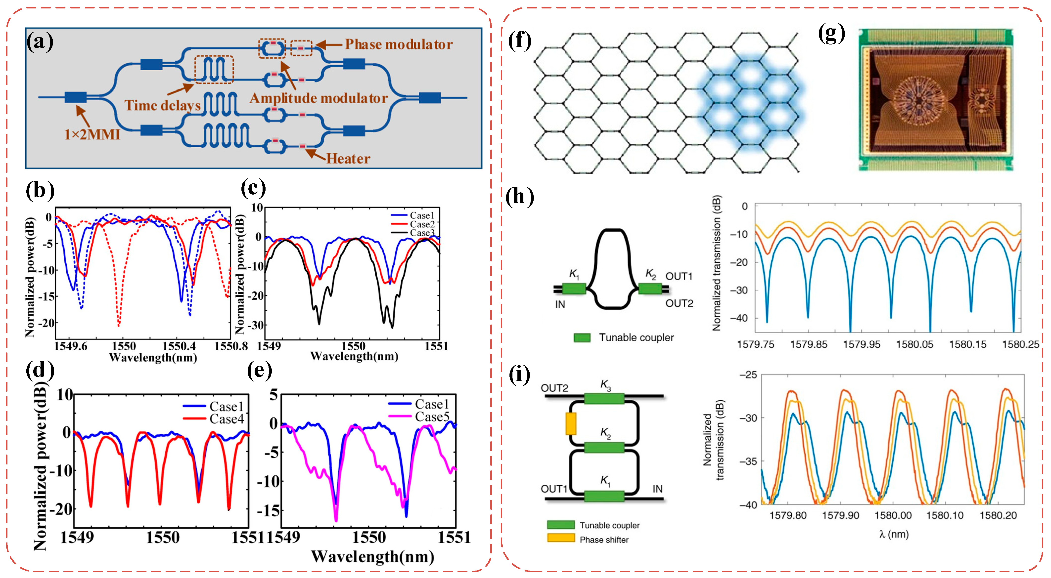
Similar to the versatile programmability of discrete signal processing algorithms, a variety of advanced and complex signal processing functions can be built flexibly and dynamically based on FIR filter configurations [132]. A silicon-based four-tap FIR programmable MPF is proposed in reference [26], as shown in Figure 21a. The MPF is divided into four taps by using cascaded multimode interference (MMI) couplers. The delay between two adjacent waveguides is 10 ps, which is achieved by using waveguides of different lengths. Both amplitude and the phase modulations are implemented with separate thermal electrodes, realizing adjustable center wavelength, bandwidth, and passband shape, as shown in Figure 21b–e. The solution offers significant advantages such as compactness and ease of integration with electronic devices. This approach also demonstrates that a stable coherent MPF can be achieved by reducing its size. Similar to electronic field-programmable gate arrays, a demonstration of silicon-based reconfigurable two-dimensional photonic waveguide networks is reported in reference [27]. As shown in Figure 21f, the mesh is composed of seven-hexagonal MZI waveguide cells. Each cell allows independent control of amplitude and phase, thus realizing a variety of photonic circuits with different structures. Figure 21h,i illustrates typical amplitude responses of the reconfigured unbalanced Mach–Zehnder Interferometer (UMZI) and a bandpass CROW structure, respectively. In addition, over 20 different configurations of photonic circuits are demonstrated, realizing classical FIR and IIR signal processing functions as well as multi-port linear optical operations. This hexagonal lattice network enhances reconfiguration performance, increases the number of switching elements per unit area, and reduces the loss of per-space resolution.
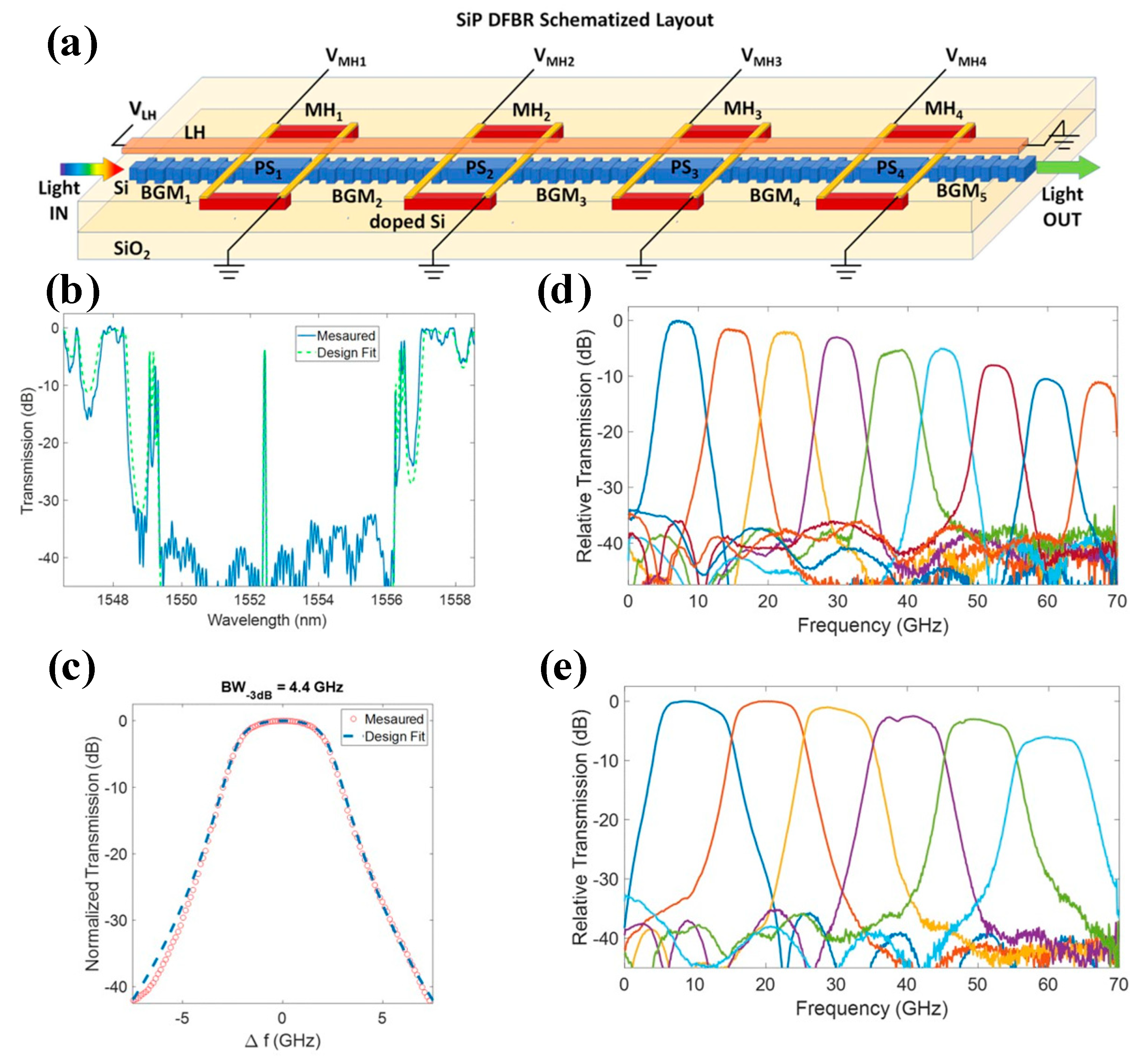
MPFs using FBGs as the delay unit have been described in discrete devices. Many works based on FBGs have realized incoherent multi-tap MPFs [30,44,133,134]. In contrast, integrated waveguide Bragg grating (WBG) can realize IMPFs due to their compactness and flexibility [28,29,135,136]. Arbitrary amplitude and phase responses can be produced by manipulating the coupling coefficients and perturbations of the grating profile [137]. A tunable and bandwidth-reconfigurable MPF has been proposed in reference [135]. The core structure of the MPF is a high-order distributed feedback resonator (DFBR) based on waveguide Bragg gratings, as shown in Figure 22a. The DFBR is realized by inserting PS segments between Bragg grating mirrors (BGMs) in a corrugated silicon strip waveguide. Therefore, fourth-order multicavity filtering can be achieved. Compared to MRR, DFBR can simplify the design of narrow bandpass transfer functions [138]. Figure 22b illustrates the measured spectral transmission of the DFBR MPF, and Figure 22c shows the details of the passband window. In this case, an FWHM bandwidth of 4.5 GHz is measured. Figure 22d,e shows the tunability from 0 to 70 GHz at reconfigurable bandwidths of 5 GHz and 10 GHz, respectively.

3.1.3. Optical All-Pass Filter

Generally, the MPFs are realized by using the amplitude frequency response of optical devices, including lowpass, highpass, bandpass, and bandstop filters. In contrast, the all-pass filter (APF) has a constant amplitude frequency response, and phases only change with frequency. Therefore, the APF can also be called a phase filter or all-pass network. Because of this unique characteristic, the APF is particularly suitable for situations where only optical phase manipulation is required, such as microwave photonic phase shifters [139,140], MPFs [104,141], the synchronization of optical time division multiplexed (OTDM) systems [142], and dispersion compensation [143,144]. Previously implemented APF does not include full-band all-pass responses, but actually includes flat-top bandpass filters with a large bandwidth [145,146,147,148]. The passband amplitude also undulates with frequency [149,150,151]. Therefore, the APF still produces resonant peaks of a smaller amplitude at resonance [152,153,154,155]. Because of the existence of waveguide loss and coupling loss, the APF directly obtained based on MRR is not truly all-pass. In order to eliminate the amplitude variation caused by loss, an APF in the passive silicon waveguide is proposed and demonstrated in reference [91]. The APF uses optical interference between the outputs of an all-pass MRR and a straight waveguide. Figure 23a shows the schematic diagram of the optical APF. The phase response can be continuously tuned by adjusting the electrical power applied to the micro heaters. The application of APF in a microwave photonic phase shifter is further explored. APF is an ideal microwave photonic phase shifter device because only the phase is changed in the frequency response, while the amplitude remains constant. The measured microwave phase is shifted from 0 to 1.84π, and the corresponding RF power variation is less than 1 dB, as shown in Figure 23b,c. In addition, the APF can also be realized by using a dual-injection MRR with self-loss compensation [92]. The structure shown in Figure 23d can be designed to realize an APF based on the MZI-assisted MRR by using the self-compensation of loss. By adjusting the operating state, the device acts as if the transmission loss from the input to the through port is compensated. When the compensation is precisely equal to the transmission loss, the APF can be realized. The measured microwave phase shift and the corresponding amplitude, with respect to the frequency, are shown in Figure 23e,f, respectively. It can be seen that the power variation is less than 0.8 dB during the microwave phase shifting. However, both of the two schemes realize first-order APFs, which achieve a phase shift range of less than 2π. In order to obtain a larger phase shift range and time delay, it is possible to directly cascade multiple first-order APFs to obtain higher-order APFs. The corresponding insertion loss and system complexity will increase consequently. To solve these problems, it is demonstrated that a second-order APF is successfully achieved by cascading a first-order APF with an all-pass MRR [93]. Results show that the phase shift can be adjusted from 0 to 3.27π. Notably, the topology of the second-order APF can be easily extended to achieve higher-order APFs.
Therefore, APF has a constant amplitude response and varied phase response and is particularly suitable for occasions where pure phase manipulations are required, such as a microwave photonic phase shifter, continuous time delay, and dispersion compensation in devices.

3.1.4. System Integration

IMPF has many unparalleled advantages over discrete-based MPF. To further reduce the size, weight, power, and cost (SWaP-C), it is also desired to realize a fully integrated microwave photonic system, including light sources, electro-optical modulators, filters, delay lines, PDs, and other functional devices. Early demonstrations of tunable and reconfigurable MPFs have been reported by integrating SOA and PM [81,82,156].
A milestone demonstration of the first full IMPF [157] was realized in 2017. The chip contains all of the core components in a complete microwave photonic system, including a tunable distributed Bragg reflection (DBR) laser, a dual-drive Mach–Zehnder modulator (DDMZM), a tunable optical filter based on a ring-assisted MZI (RAMZI), and an InP PD. As shown in Figure 24a, the image of a fabricated die is approximately 6 × 4 mm2. The packaged system is shown in Figure 24b. Based on this compact photonic circuit, an RF bandpass filter with a GHz-level bandwidth and moderate tunability is successfully implemented, as shown in Figure 24c. Although the performance of the MPF is constrained by the modulation bandwidth, relatively high waveguide loss, and RF crosstalk, this integration of a microwave photonic system is still the first successful attempt. The performance in the future can be improved based on the high-performance components based on the InP platform [132], including a high-power laser with low relative intensity noise (RIN), MZMs with low half-wave voltage, and high-efficiency PDs with high responsivity [158,159,160,161,162].
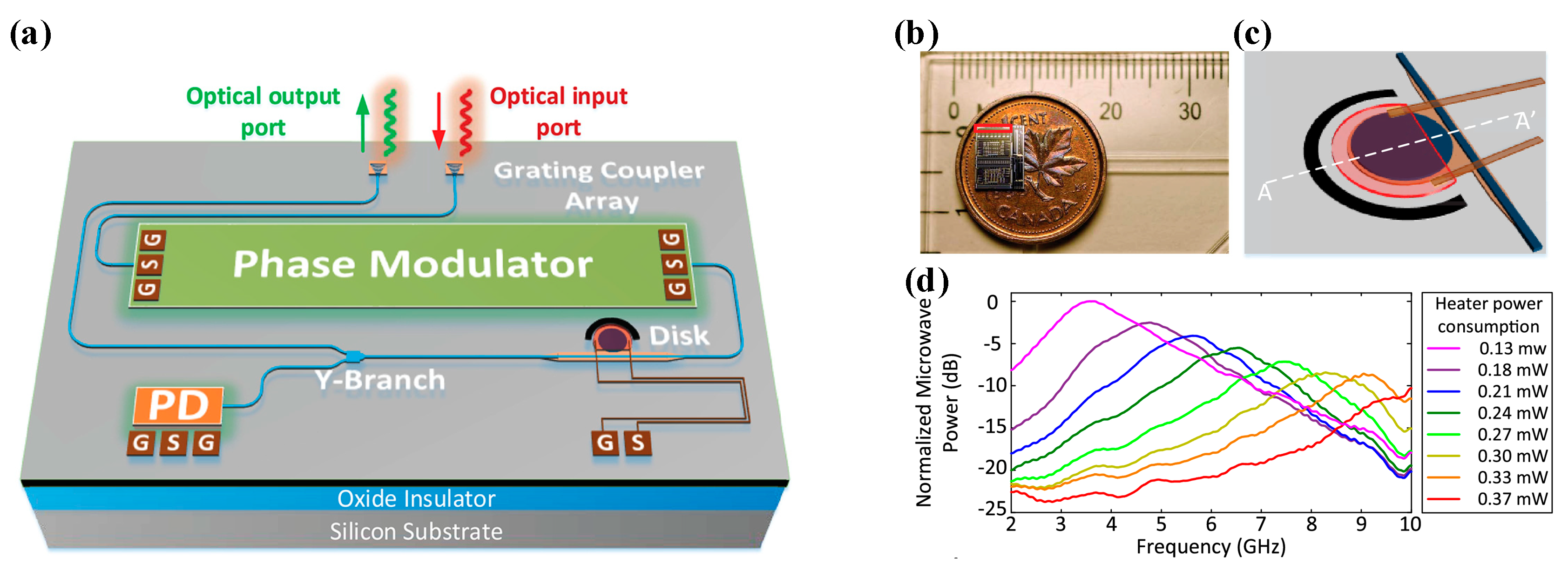
As a widely used platform for IMPFs [163,164], silicon-based photonic circuits offer compact size, low loss [120,165], and high-speed modulators [166,167] and PDs [168]. In reference [169], a silicon-based multifunctional integrated MPF is reported, as shown in Figure 25a. A high-speed PM, a thermally tunable high-Q MDR, and a high-speed PD are integrated on the chip. Based on the integrated chip, a bandpass MPF is achieved. The FWHM bandwidth is 1.93 GHz, and the center frequency can be tuned from 3 to 10 GHz. Additionally, the estimated power consumption of tuning the MPF is no more than 0.37 mW. If the microwave signal output from the MPF is fed back to the RF port of the PM, an integrated OEO can be obtained when the loop gain is higher than the loss [170]. The oscillation frequency of OEO is determined by the center frequency of the MPF. The center frequency of the MPF can be tuned by adjusting the electrical power applied to the micro heaters on the MDR. Therefore, the OEO oscillation frequency can be tuned. Notably, silicon is an indirect bandgap material with low luminescence efficiency. Consequently, the implementation of a silicon-based light source is the most difficult constraint for silicon-based fully monolithic integration.
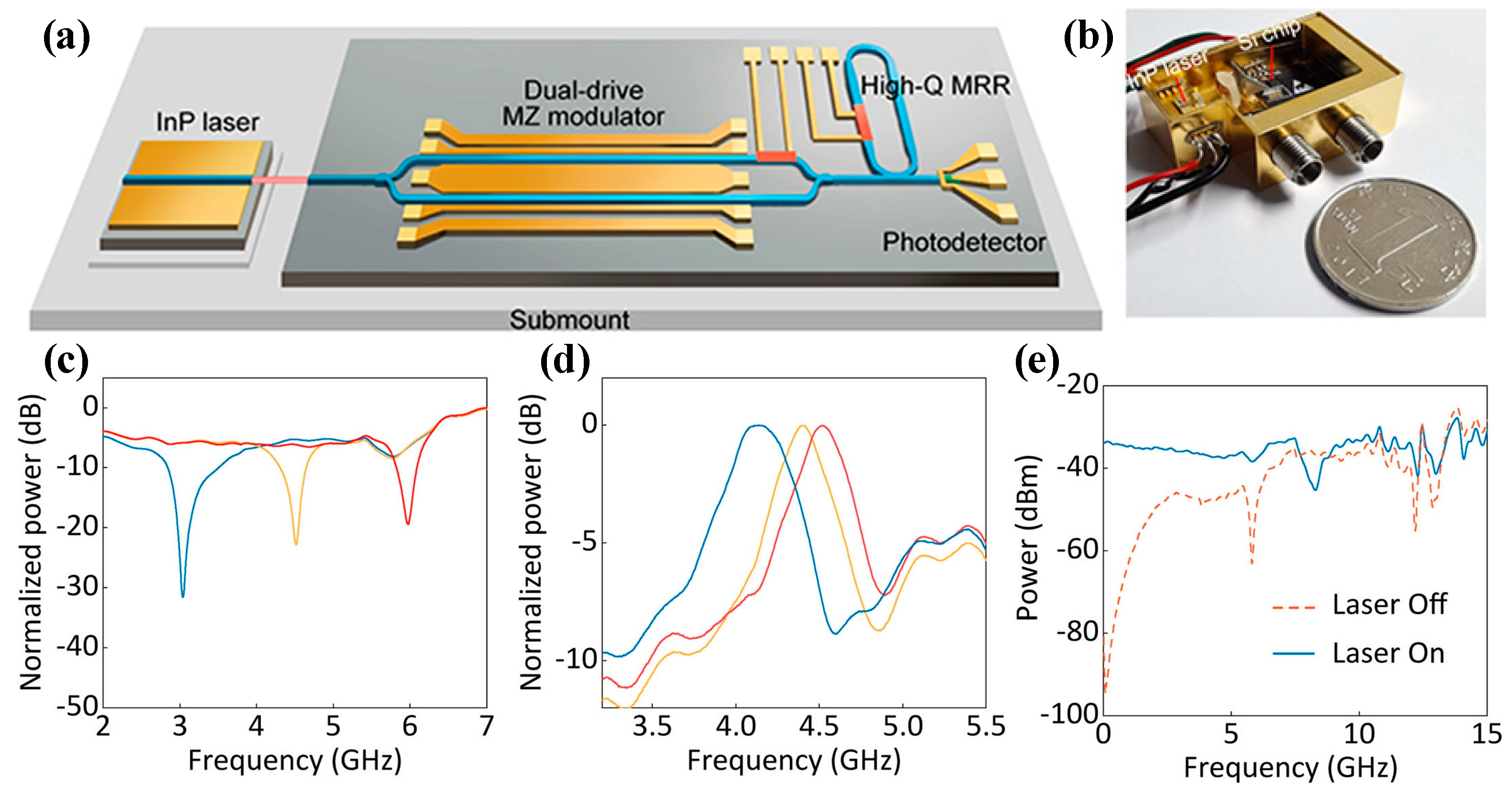
The InP platform enables the monolithic integration of all active and passive devices. However, the large transmission loss severely limits the resolution bandwidth. Due to the low loss, Si and Si3N4 platforms are ideal candidates for achieving high-resolution bandwidths. Unfortunately, the optical source integration on these substrates is still a long-standing challenge. To solve this problem, hybrid integration has recently been recognized as a feasible way to build effective bridges between different material platforms [171]. A hybrid integrated MPF that achieved high filtering performance is demonstrated in reference [105]. The MPF is realized through the hybrid integration of an InP chip-based laser and a monolithic silicon photonic circuit consisting of a DDMZM, a high-Q MRR, and a PD. As shown in Figure 26a, the footprint value of the chip is approximately 1.34 × 3.18 mm2. In the hybrid integration process, the InP-based LD chip and the Si photonic chip are optically connected based on off-the-shelf micro-optic components. The devices are assembled into a compact package, as shown in Figure 26b. This IMPF features a high-resolution bandwidth of 360 MHz, a wide frequency tuning range from S-band to K-band (3–25 GHz), and a large rejection ratio over 40 dB, as shown in Figure 26c–e. In addition, the amplitude frequency responses of the IMPF can be flexibly switched between bandpass and bandstop functions. The scheme uses a hybrid integration approach to realize miniaturized, high-performance, and low-cost MPF.

3.2. Applications of IMPF

Compared with the MPF based on discrete devices, IMPF can be applied to integrated microwave photonic systems, which is advantageous with its small size, light weight, low power consumption, and low cost.

3.2.1. Integrated OEO

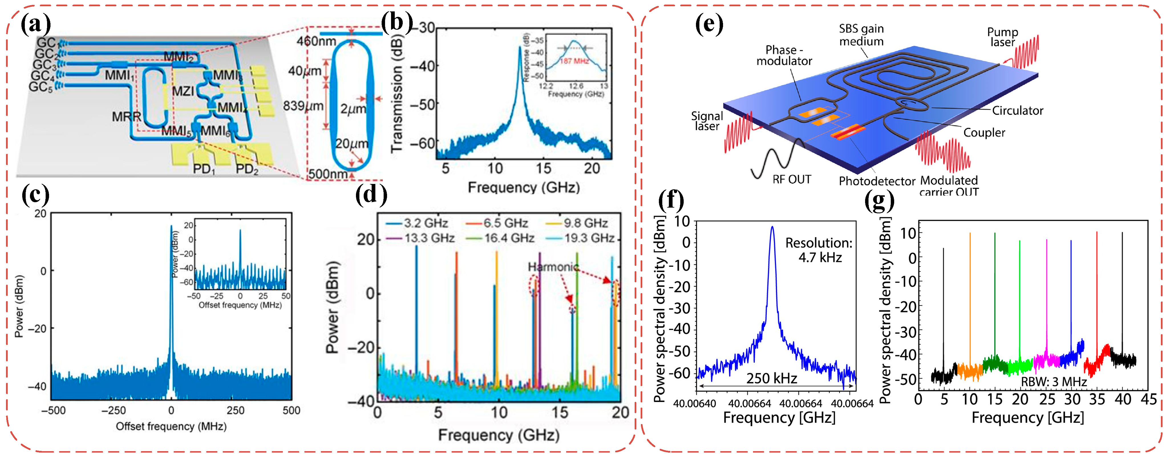
As mentioned in Section 2.2.1, the application of MPFs in OEO offers various advantages, including low phase noise and broadband tunability and high stability. However, most OEOs are implemented based on discrete devices and have a large size, heavy weight, and high power consumption and cost. The silicon-based IMPF in reference [169] utilizes a high-Q MDR, and an integrated OEO can be realized by feeding the MPF output back to the PM [170]. In reference [20], an on-chip tunable PT-symmetric OEO based on an SOI wafer is realized. A high-Q MRR, an adjustable MZI, and two high-speed PDs are monolithically integrated on the chip. The MRR is used to implement a tunable MPF for performing coarse mode selection. To obtain a narrower bandwidth, the optical waveguide scattering loss is reduced by increasing the waveguide width. To ensure single mode propagation, the wide waveguide is connected with a single mode waveguide by an adiabatic taper, as shown in Figure 27a. Figure 27b illustrates the transmission of the MPF. The combination of high-quality MPF and PT symmetry significantly enhances mode selection and enables the OEO oscillation frequency to be widely tuned. Results show that stable single-mode oscillation of the OEO is achieved, and the oscillation frequency can be tuned from 0 to 20 GHz, as shown in Figure 27c,d. Additionally, the on-chip SBS can also generate a narrow-band MPF, which can be used for mode selection in OEO. Reference [21] reports a chip-based highly pure microwave source harnessing SBS. The design and construction of the integrated OEO are shown in Figure 27e. The SBS-based MPF also provides gain to the cavity, and no additional re-amplification is required to compensate for the link loss. Because of the large Brillouin gain employed in a short cavity [172,173], the OEO can achieve single mode oscillation with high stability without detrimental mode hopping. Figure 27f shows the measured electrical spectrum of the OEO, which shows a narrow linewidth. Figure 27g shows that the oscillation frequency of the SBS-based OEO can be tuned from 5 to 40 GHz.

3.2.2. Integrated Microwave Photonic Frequency Measurement

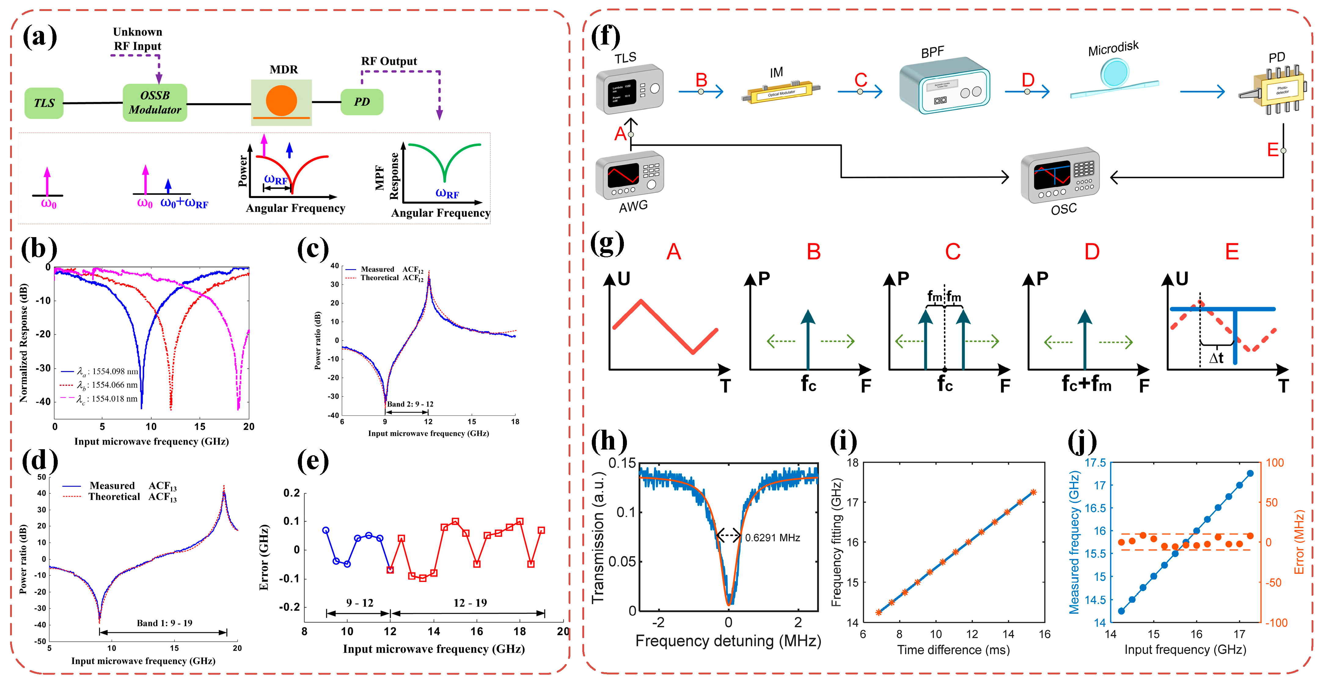
In Section 2.2, several schemes of achieving photonic-assisted microwave IFM were introduced. However, IFMs based on discrete devices are usually large and have low stability against environmental disturbances. In addition to the schemes mentioned above, integrated optoelectronic devices, such as Bragg gratings [25], MRRs [174,175], MZIs [176], and MDRs [24,177], can also be used to realize the frequency-to-power mapping (FTPM). IFM can be achieved by establishing the relationship between the output power and the microwave frequency. To adapt different applications, it is required to achieve an adjustable measurement range and high accuracy. A chip-based microwave photonic notch filter using an integrated silicon MDR can be utilized in microwave IFM with an adjustable measurement range [24]. The schematic diagram of the microwave frequency measurement system is shown in Figure 28a. Figure 28b shows the measured amplitude frequency responses with different laser wavelengths. Therefore, different ACFs can be calculated, and finally, a fixed FTPM can be obtained post-processing. Figure 28e shows that the measurement error is ±0.2 GHz when the measurement range is from 9 to 19 GHz. However, there is a trade-off between the accuracy and measurement range. Namely, a smaller measurement range results in a higher resolution. Reducing the frequency measurement range can increase the steepness of the ACF curve, thus improving the frequency measurement accuracy.
In addition to the FTPM scheme, frequency-to-time mapping (FTTM) can also be used to establish the relationship between microwave frequency and time. Although FTTM does not support IFM, it can be used to obtain the frequencies of microwave signals with different types, including single-frequency signal, multi-frequency signal, frequency-hopping signal, and frequency-chirped signals. It is also essential to achieve higher accuracy. In reference [178], an FTTM scheme is proposed based on an ultra-high Q factor MDR. The schematic diagram of the frequency measurement is shown in Figure 28f, and Figure 28g shows the waveforms corresponding to points A, B, C, D, and E, respectively. The unknown microwave signal is firstly modulated by an intensity modulator (IM) to a periodically sweeping triangular wave and then filtered by a band pass filter to remove one sideband and input to a high-Q MDR. Finally, an oscilloscope (OSC) displays the electrical signals received by the PD. When the input optical frequency is exactly equal to one of the resonant frequencies of the MDR, a depression will appear on the OSC. There will be a time difference ∆t between the appearance of the depression and the beginning of the falling edge of the triangle wave, as shown by the waveform at point E in Figure 28g. Therefore, a mapping of microwave frequency to time can be established, and the unknown microwave frequency can be identified by measuring ∆t. For the magnesium fluoride MDR, Figure 28h shows an FWHM bandwidth of 0.6291 MHz at a wavelength of 1556.77 nm. Figure 28i illustrates the linear relationship between ∆t and microwave frequency, and Figure 28j shows the calculated frequency measurement error from 14.25 to 17.25 GHz. It can be noted that the error remains below 10 MHz over the tested 3 GHz range. This scheme provides a solution to realizing a high-performance microwave frequency measurement system with small size and light weight.

4. Conclusions

The MPF has been emerging as a promising technology to meet the growing demands of modern communication systems, and it offers a wide range of advantages over traditional electronic filters. In this review, we provide a comprehensive introduction of MPFs, discussing their theoretical foundations, various applications, and the evolution of these MPFs from discrete to integrated devices. These concepts are the cornerstone for designing and analyzing MPFs, enabling researchers and engineers to explore new possibilities in signal processing and filtering. Various applications of MPFs are discussed, demonstrating their versatility and effectiveness in different fields. OEOs benefit from MPFs to achieve wide frequency tunability and reconfigurable signals. Advances in microwave frequency measurements have also been made through integrated photonic technology, improving the accuracy and bandwidth of frequency measurements. In addition, novel filter functions, such as APF, are also introduced. APF is a good device to manipulate signal phases. Therefore, microwave photonic phase shifting and adjustable time delay line can be obtained based on APF. The evolution of MPFs from discrete to integrated devices has played a crucial role in expanding their utility and integration into existing systems. These on-chip integrated devices offer compactness, scalability, and higher reliability. However, challenges such as fabrication complexity and device performance limitations need to be addressed to fully realize the potential of IMPFs. For the fast development of MPFs, as well as fabrication techniques and materials, we believe that MPFs have great potential for shaping the future of MWP, enabling new capabilities in various fields and promoting advances in communication and signal processing systems.

Author Contributions

Y.Z. drafted the manuscript; Y.Y. supervised the work; Y.Y., Y.Z., L.W. and Y.L. commented, edited, and reviewed the manuscript; Y.Y. and X.Z. supervised the project. All authors have read and agreed to the published version of the manuscript.

Funding

This research was funded by the National Natural Science Foundation of China, grant number 61975249, the National Key Research and Development Program of China, grant number 2018YFB2201700 and 2018YFA0704403, and the Program for HUST Academic Frontier Youth Team, grant number 2018QYTD08.

Institutional Review Board Statement

Not applicable.

Informed Consent Statement

Not applicable.

Data Availability Statement

Not applicable.

Conflicts of Interest

The authors declare no conflict of interest.

References

  1. Yao, J. Microwave photonics. J. Light. Technol. 2009, 27, 314–335. [Google Scholar] [CrossRef]
  2. Seeds, A.J.; Williams, K.J. Microwave Photonics. J. Light. Technol. 2006, 24, 4628–4641. [Google Scholar] [CrossRef]
  3. Li, M.; Zhu, N. Recent advances in microwave photonics. Front. Optoelectron. 2016, 9, 160–185. [Google Scholar] [CrossRef]
  4. Borges, R.M.; Muniz, A.L.M.; Sodre, A.C. Development and Performance Analysis of a Photonics-Assisted RF Converter for 5G Applications. Fiber Integr. Opt. 2017, 36, 25–37. [Google Scholar] [CrossRef]
  5. Waterhouse, R.; Novack, D. Realizing 5G: Microwave photonics for 5G mobile wireless systems. IEEE Microw. Mag. 2015, 16, 84–92. [Google Scholar] [CrossRef]
  6. Capmany, J.; Novak, D. Microwave photonics combines two worlds. Nat. Photon. 2007, 1, 319–330. [Google Scholar] [CrossRef]
  7. Yao, J. Microwave Photonic Systems. J. Light. Technol. 2022, 40, 6595–6607. [Google Scholar] [CrossRef]
  8. Marpaung, D.; Yao, J.; Capmany, J. Integrated microwave photonics. Nat. Photon. 2019, 13, 80–90. [Google Scholar] [CrossRef]
  9. Loayssa, A.; Capmany, J.; Sagues, M.; Mora, J. Demonstration of incoherent microwave photonic filters with all-optical complex coefficients. IEEE Photon. Technol. Lett. 2006, 18, 1744–1746. [Google Scholar] [CrossRef]
  10. Xue, X.; Zheng, X.; Zhang, H.; Zhou, B. Widely tunable single-bandpass microwave photonic filter employing a non-sliced broadband optical source. Opt. Express 2011, 19, 18423–18429. [Google Scholar] [CrossRef]
  11. Wang, W.; Liu, J.; Sun, W.; Wang, W.; Wang, S.; Zhu, N. Widely tunable single bandpass microwave photonic filter based on Brillouin-assisted optical carrier recovery. Opt. Express 2014, 22, 29304–29313. [Google Scholar] [CrossRef]
  12. Song, M.; Long, C.; Wu, R.; Seo, D.; Leaird, E.; Weiner, A.M. Reconfigurable and Tunable Flat-Top Microwave Photonic Filters Utilizing Optical Frequency Combs. IEEE Photon. Technol. Lett. 2011, 23, 1618–1620. [Google Scholar] [CrossRef]
  13. Preussler, S.; Zadok, A.; Stern, Y.; Schneider, T. Microwave-photonic filters. In Proceedings of the 2016 German Microwave Conference (GeMiC), Bochum, Germany, 14–16 March 2016. [Google Scholar]
  14. Yu, Y.; Xu, E.; Dong, J.; Zhou, L.; Li, X.; Zhang, X. Switchable microwave photonic filter between high Q bandpass filter and notch filter with flat passband based on phase modulation. Opt. Express 2010, 8, 25271–25282. [Google Scholar] [CrossRef]
  15. Zhang, W.; Minasian, R.A. Switchable and Tunable Microwave Photonic Brillouin-Based Filter. IEEE Photon. J. 2012, 4, 1443–1455. [Google Scholar] [CrossRef]
  16. Capmany, J.; Ortega, B.; Pastor, D.; Sales, S. Discrete-time optical Processing of microwave signals. J. Light. Technol. 2005, 23, 702–723. [Google Scholar] [CrossRef]
  17. Xu, E. Microwave Photonic Filters Based on Semiconductor Optical Amplifier. Ph.D. Dissertation, Huazhong University of Science and Technology, Wuhan, China, 2010. [Google Scholar]
  18. Jiang, F.; Wong, J.H.; Lam, H.Q.; Zhou, J.; Aditya, S.; Lim, P.H.; Lee, K.E.K.; Shum, P.P.; Zhang, X. An optically tunable wideband optoelectronic oscillator based on a bandpass microwave photonic filter. Opt. Express 2013, 21, 16381–16389. [Google Scholar] [CrossRef] [PubMed]
  19. Tang, H.; Yu, Y.; Wang, Z.; Xu, L.; Zhang, X. Wideband tunable optoelectronic oscillator based on a microwave photonic filter with an ultra-narrow passband. Opt. Lett. 2018, 43, 2328–2331. [Google Scholar] [CrossRef]
  20. Wang, L.; Xiao, X.; Xu, L.; Liu, Y.; Chen, Y.; Yu, Y.; Zhang, X. On-chip tunable parity-time symmetric optoelectronic oscillator. Adv. Photon. Nexus 2023, 2, 016004. [Google Scholar] [CrossRef]
  21. Merklein, M.; Stiller, B.; Kabakova, I.V.; Mutugala, U.S.; Vu, K.; Madden, S.J.; Eggleton, B.J.; Slavík, R. Widely tunable, low phase noise microwave source based on a photonic chip. Opt. Lett. 2016, 41, 4633–4636. [Google Scholar] [CrossRef] [PubMed]
  22. Li, M.; Hao, T.; Li, W.; Dai, Y. Tutorial on optoelectronic oscillators. APL Photon. 2021, 6, 061101. [Google Scholar] [CrossRef]
  23. Hao, T.; Liu, Y.; Tang, J.; Cen, Q.; Li, W.; Zhu, N.; Dai, Y.; Capmany, J.; Yao, J.; Li, M. Recent advances in optoelectronic oscillators. Adv. Photon. 2020, 2, 044001. [Google Scholar] [CrossRef]
  24. Liu, L.; Jiang, F.; Yan, S.; Min, S.; He, M.; Gao, D.; Dong, J. Photonic measurement of microwave frequency using a silicon microdisk resonator. Opt. Commun. 2015, 335, 266–270. [Google Scholar] [CrossRef]
  25. Burla, M.; Wang, X.; Li, M.; Chrostowski, L.; Azana, J. Wideband dynamic microwave frequency identification system using a low-power ultracompact silicon photonic chip. Nat. Commun. 2016, 7, 13004. [Google Scholar] [CrossRef] [PubMed]
  26. Liao, S.; Ding, Y.; Peucheret, C.; Yang, T.; Dong, J.; Zhang, X. Integrated programmable photonic filter on the silicon-on-insulator platform. Opt. Express 2014, 22, 31993–31998. [Google Scholar] [CrossRef]
  27. Pérez, D.; Gasulla, I.; Crudgington, L.; Thomson, D.J.; Khokhar, A.Z.; Li, K.; Cao, W.; Mashanovich, G.Z.; Capmany, J. Multipurpose silicon photonics signal processor core. Nat. Commun. 2017, 8, 636. [Google Scholar] [CrossRef] [PubMed]
  28. Yao, J.; Zhang, W. Fully Reconfigurable Waveguide Bragg Gratings for Programmable Photonic Signal Processing. J. Light. Technol. 2020, 38, 202–214. [Google Scholar] [CrossRef]
  29. Zhang, W.; Yao, J. A fully reconfigurable waveguide Bragg grating for programmable photonic signal processing. Nat. Commun. 2018, 9, 1396. [Google Scholar] [CrossRef]
  30. Capmany, J.; Ortega, B.; Pastor, D. A Tutorial on Microwave Photonic Filters. J. Light. Technol. 2006, 24, 201–229. [Google Scholar] [CrossRef]
  31. Vidal, B.; Corral, J.L.; Marti, J. WDM photonic microwave filter using nonuniform wavelength spacing. In Proceedings of the 2004 IEEE International Topical Meeting on Microwave Photonics, Ogunquit, ME, USA, 4–6 October 2004. [Google Scholar]
  32. Vidal, B.; Polo, V.; Corral, J.L.; Marti, J. Photonic microwave filter with negative coefficients based on WDM techniques. IEEE Photon. Technol. Lett. 2004, 16, 2123–2125. [Google Scholar] [CrossRef]
  33. Wang, W.; Liu, J.; Mei, H.; Sun, W.; Wang, X.; Zhu, N. Reconfigurable microwave photonic filter based on Brillouin-assisted narrowband rectangular optical amplifier. In Proceedings of the 2015 14th International Conference on Optical Communications and Networks (ICOCN), Nanjing, China, 3–5 July 2015. [Google Scholar]
  34. Chan, E.H.W.; Minasian, R.A. Coherence-free microwave photonic notch filter with a wide passband and a narrow notch. In Proceedings of the 2008 International Topical Meeting on Microwave Photonics Jointly Held with the 2008 Asia-Pacific Microwave Photonics Conference, Gold Coast, QLD, Australia, 9 September–3 October 2008. [Google Scholar]
  35. Yost, T.A.; Herczfeld, P.; Rosen, A.; Singh, S. Hybrid transversal filter utilizing MMIC and optical fiber delay lines. IEEE Microw. Guid. Lett. 1995, 5, 287–289. [Google Scholar] [CrossRef]
  36. Li, X.; Dong, J.; Yu, Y.; Zhang, X. A Tunable Microwave Photonic Filter Based on an All-Optical Differentiator. IEEE Photon. Technol. Lett. 2011, 23, 308–310. [Google Scholar] [CrossRef]
  37. Vidal, B.; Piqueras, M.A.; Marti, J. Photonic microwave filter based on spectrum slicing with reconfiguration capability. Electron. Lett. 2005, 41, 1286–1287. [Google Scholar] [CrossRef]
  38. Xu, E.; Li, P.; Wang, F.; Guan, J. Microwave photonic filters based on optical semiconductor amplifier. Front. Optoelectron. China 2011, 4, 270–276. [Google Scholar] [CrossRef]
  39. Zhang, W.; Williams, J.A.R.; Everall, L.A.; Bennion, I. Fiber-optic radio frequency notch filter with linear and continous tuning by using a chirped fiber grating. Electron. Lett. 1998, 34, 1770–1772. [Google Scholar] [CrossRef]
  40. Pan, S.; Tang, Z.; Huang, M.; Li, S. Reflective-Type Microring Resonator for On-Chip Reconfigurable Microwave Photonic Systems. IEEE J. Sel. Top. Quant. 2020, 26, 1–12. [Google Scholar] [CrossRef]
  41. Lu, Z.; Li, J.; Wu, Y.; Chen, H.; Yang, S.; Chen, M. Reconfigurable RF Filter Based on Cascaded Microring Resonators. IEEE Photon. J. 2023, 15, 1–6. [Google Scholar] [CrossRef]
  42. Li, S.; Cong, R.; He, Z.; Wang, T.; Zhang, F.; Pan, S. Switchable microwave photonic filter using a phase modulator and a silicon-on-insulator micro-ring resonator. Chin. Opt. Lett. 2020, 18, 052501. [Google Scholar] [CrossRef]
  43. Shahoei, H.; Yao, J. A continuously tunable multi-tap complex-coefficient microwave photonic filter based on a tilted fiber Bragg grating. Opt. Express 2013, 21, 7521–7527. [Google Scholar] [CrossRef] [PubMed]
  44. Zeng, F.; Wang, J.; Yao, J. All-optical microwave bandpass filter with negative coefficients based on a phase modulator and linearly chirped fiber Bragg gratings. Opt. Lett. 2005, 30, 2203–2205. [Google Scholar] [CrossRef]
  45. Mora, J.; Ortega, B.; Capmany, J.; Cruz, J.L.; Andrés, M.V.; Pastor, D.; Sales, S. Automatic tunable and reconfigurable fiber-optic microwave filters based on a broadband optical source sliced by uniform fiber Bragg gratings. Opt. Express 2002, 10, 1291–1298. [Google Scholar] [CrossRef]
  46. Liu, X. Study of Sililcon-Based Integrated Microwave Photonic Filter. Master’s Thesis, Huazhong University of Science and Technology, Wuhan, China, 2018. [Google Scholar]
  47. Dai, Y.; Yao, J. Nonuniformly Spaced Photonic Microwave Delay-Line Filters and Applications. IEEE Trans. Microw. Theory Tech. 2010, 58, 3279–3289. [Google Scholar] [CrossRef]
  48. Han, Y.; Li, Z.; Yao, J. A Microwave Bandpass Differentiator Implemented Based on a Nonuniformly-Spaced Photonic Microwave Delay-Line Filter. J. Light. Technol. 2011, 29, 3470–3475. [Google Scholar]
  49. Moslehi, B.; Goodman, J.; Tur, M.; Shaw, H.J. Fiber-optic lattice signal processing. Proc. IEEE 1984, 72, 909–930. [Google Scholar] [CrossRef]
  50. Xu, E.; Zhang, X.; Zhou, L.; Zhang, Y.; Huang, D. A simple microwave photonic notch filter based on a semiconductor optical amplifier. J. Opt. A Pure Appl. Opt. 2009, 11, 085405. [Google Scholar] [CrossRef]
  51. Zhang, W.; Yu, G.; Williams, J.A.R. Tap multiplexed fibre grating-based optical transversal filter. Electron. Lett. 2000, 36, 1708–1710. [Google Scholar] [CrossRef]
  52. Pastor, D.; Ortega, B.; Capmany, J.; Sales, S.; Martinez, A.; Muñoz, P. Optical microwave filter based on spectral slicing by use of arrayed waveguide gratings. Opt. Lett. 2003, 28, 1802–1804. [Google Scholar] [CrossRef]
  53. Vidal, B.; Polo, V.; Corral, J.L.; Marti, J. Cost-effective photonic microwave filter employing tap reusing. In Proceedings of the MWP 2003 Proceedings. International Topical Meeting on Microwave Photonics, Budapest, Hungary, 10–12 September 2003. [Google Scholar]
  54. Zhou, L.; Zhang, X.; Xu, E.; Yu, Y.; Li, X.; Huang, D. A novel tunable cascaded IIR microwave photonic filter. Opt. Commun. 2010, 283, 2794–2797. [Google Scholar] [CrossRef]
  55. Chan, E.H.W.; Minasian, R.A. Reflective Amplified Recirculating Delay Line Bandpass Filter. J. Light. Technol. 2007, 25, 1441–1446. [Google Scholar] [CrossRef]
  56. Pan, S.; Yao, J. Photonics-Based Broadband Microwave Measurement. J. Light. Technol. 2017, 35, 3498–3513. [Google Scholar] [CrossRef]
  57. Zou, X.; Lu, B.; Pan, W.; Yan, L.; Stöhr, A.; Yao, J. Photonics for microwave measurements. Laser Photon. Rev. 2016, 10, 711–734. [Google Scholar] [CrossRef]
  58. Wang, W.S.; Davis, R.L.; Jung, T.J.; Lodenkamper, R.; Lembo, L.J.; Brock, J.C.; Wu, M.C. Characterization of a coherent optical RF channelizer based on a diffraction grating. IEEE Trans. Microw. Theory Tech. 2001, 49, 1996–2001. [Google Scholar] [CrossRef]
  59. Winnall, S.T.; Lindsay, A.C.; Austin, M.W.; Canning, J.; Mitchell, A. A microwave channelizer and spectroscope based on an integrated optical Bragg-grating Fabry–Pérot and integrated hybrid Fresnel lens system. IEEE Trans. Microw. Theory Tech. 2006, 54, 868–872. [Google Scholar] [CrossRef]
  60. Hunter, D.B.; Edvell, L.G.; Englund, M.A. Wideband microwave photonic channelised receiver. In Proceedings of the 2005 International Topical Meeting on Microwave Photonics, Seoul, Republic of Korea, 14 October 2005. [Google Scholar]
  61. Nguyen, L.V.T. Microwave photonic technique for frequency measurement of simultaneous signals. IEEE Photon. Technol. Lett. 2009, 21, 642–644. [Google Scholar] [CrossRef]
  62. Nguyen, T.A.; Chan, E.H.W.; Minasian, R.A. Photonic Multiple Frequency Measurement Using a Frequency Shifting Recirculating Delay Line Structure. J. Light. Technol. 2014, 32, 3831–3838. [Google Scholar] [CrossRef]
  63. Zhou, Y.; Zhang, F.; Shi, J.; Pan, S. Deep neural network-assisted high-accuracy microwave instantaneous frequency measurement with a photonic scanning receiver. Opt. Lett. 2020, 45, 3038–3041. [Google Scholar] [CrossRef]
  64. Zhou, J.; Aditya, S.; Shum, P.P.; Yao, J. Instantaneous Microwave Frequency Measurement Using a Photonic Microwave Filter with an Infinite Impulse Response. IEEE Photon. Technol. Lett. 2010, 22, 682–684. [Google Scholar] [CrossRef]
  65. Yao, X.S.; Maleki, L. Optoelectronic microwave oscillator. J. Opt. Soc. Am. B 1996, 13, 1725–1735. [Google Scholar] [CrossRef]
  66. Maleki, L. The optoelectronic oscillator. Nat. Photon. 2011, 5, 728–730. [Google Scholar] [CrossRef]
  67. Yao, X.S.; Maleki, L. Optoelectronic oscillator for photonic systems. IEEE J. Quantum Electron. 1996, 32, 1141–1149. [Google Scholar] [CrossRef]
  68. Salik, E.; Yu, N.; Maleki, L. An Ultralow Phase Noise Coupled Optoelectronic Oscillator. IEEE Photon. Technol. Lett. 2007, 19, 444–446. [Google Scholar] [CrossRef]
  69. Zhang, J.; Gao, L.; Yao, J. Tunable Optoelectronic Oscillator Incorporating a Single Passband Microwave Photonic Filter. IEEE Photon. Technol. Lett. 2014, 26, 326–329. [Google Scholar] [CrossRef]
  70. Poinsot, S.; Porte, H.; Goedgebuer, J.P.; Rhodes, W.T.; Boussert, B. Continuous radio-frequency tuning of an optoelectronic oscillator with dispersive feedback. Opt. Lett. 2002, 27, 1300–1302. [Google Scholar] [CrossRef]
  71. Yu, Y. Investigation of All-Optical Microwave Signal Processing Techniques. Ph.D. Dissertation, Huazhong University of Science and Technology, Wuhan, China, 2013. [Google Scholar]
  72. Yao, J. Photonics to the Rescue: A Fresh Look at Microwave Photonic Filters. IEEE Microw. Mag. 2015, 16, 46–60. [Google Scholar] [CrossRef]
  73. Sales, S.; Capmany, J.; Marti, J. Experimental demonstration of fibre-optic delay line filters with negative coefficients. Electron. Lett. 1995, 31, 1095–1096. [Google Scholar] [CrossRef]
  74. Li, J.; Cheung, K.K.Y.; Wong, K.K.Y. Photonic Microwave Filter with Negative Coefficients Using Fiber Optical Parametric Amplifier. In Proceedings of the National Fiber Optic Engineers Conference, San Diego, CA, USA, 22–26 March 2009. [Google Scholar]
  75. Li, X.; Yu, Y.; Dong, J.; Zhang, X. Widely Tunable Microwave Photonic Filter Based on Semiconductor Optical Amplifier. In Proceedings of the Asia Communications and Photonics Conference and Exhibition, Shanghai, China, 8–12 December 2010. [Google Scholar]
  76. Mora, J.; Martínez, A.; Manzanedo, M.D.; Capmany, J. Microwave photonic filters with arbitrary positive and negative coefficients using multiple phase inversion in SOA based XGM wavelength converter. Electron. Lett. 2005, 41, 921–922. [Google Scholar] [CrossRef]
  77. Yi, X.; Fang, W.; Hong, N.J.; Lu, C. Tunable microwave filter design using wavelength conversion technique and high dispersion time delays. IEEE Photon. Technol. Lett. 2001, 13, 857–859. [Google Scholar]
  78. Zheng, R.; Alameh, K.; Lee, Y.K.; Wang, Z. Multitap coherence-free photonic RF filter employing semiconductor optical amplifier. Microw. Opt. Technol. Lett. 2007, 49, 1103–1106. [Google Scholar] [CrossRef]
  79. Pastor, D.; Capmany, J.; Ortega, B.; Martinez, A.; Pierno, L.; Varasi, M. Reconfigurable RF photonic filter with negative coefficients and flat-top resonances using phase inversion in a newly designed designed 2×1 integrated Mach-Zehnder modulator. IEEE Photon. Technol. Lett. 2004, 16, 2126–2128. [Google Scholar] [CrossRef]
  80. Norberg, E.J.; Guzzon, R.S.; Nicholes, S.C.; Parker, J.S.; Coldren, L.A. Programmable Photonic Lattice Filters in InGaAsP–InP. IEEE Photon. Technol. Lett. 2010, 22, 109–111. [Google Scholar] [CrossRef]
  81. Norberg, E.J.; Guzzon, R.S.; Parker, J.S.; Johansson, L.A.; Coldren, L.A. Programmable Photonic Microwave Filters Monolithically Integrated in InP–InGaAsP. J. Light. Technol. 2011, 29, 1611–1619. [Google Scholar] [CrossRef]
  82. Guzzon, R.S.; Norberg, E.J.; Parker, J.S.; Johansson, L.A.; Coldren, L.A. Integrated InP-InGaAsP tunable coupled ring optical bandpass filters with zero insertion loss. Opt. Express 2011, 19, 7816–7826. [Google Scholar] [CrossRef] [PubMed]
  83. Li, X.; Xu, E.; Zhou, L.; Yu, Y.; Dong, J.; Zhang, X. Microwave photonic filter with multiple taps based on single semiconductor optical amplifier. Opt. Commun. 2010, 283, 3026–3029. [Google Scholar] [CrossRef]
  84. Coppinger, F.; Yegnanarayanan, S.; Trinh, P.D.; Jalali, B. All-optical RF filter using amplitude inversion in a semiconductor optical amplifier. IEEE Trans. Microw. Theory Tech. 1997, 45, 1473–1477. [Google Scholar] [CrossRef]
  85. Xu, E.; Zhang, X.; Zhou, L.; Zhang, Y.; Yu, Y.; Li, X.; Huang, D. All-optical microwave filter with high frequency selectivity based on semiconductor optical amplifier and optical filter. J. Light. Technol. 2010, 28, 2358–2365. [Google Scholar]
  86. Sagues, M.; Loayssa, A.; Capmany, J. Multitap Complex-Coefficient Incoherent Microwave Photonic Filters Based on Stimulated Brillouin Scattering. IEEE Photon. Technol. Lett. 2007, 19, 1194–1196. [Google Scholar] [CrossRef]
  87. Yan, Y.; Yao, J. A Tunable Photonic Microwave Filter with a Complex Coefficient Using an Optical RF Phase Shifter. IEEE Photon. Technol. Lett. 2007, 19, 1472–1474. [Google Scholar] [CrossRef]
  88. Li, W.; Zhang, W.; Yao, J. A wideband 360° photonic-assisted microwave phase shifter using a polarization modulator and a polarization-maintaining fiber Bragg grating. Opt. Express 2012, 20, 29838–29843. [Google Scholar] [CrossRef]
  89. Zhang, Y.; Pan, S. Complex Coefficient Microwave Photonic Filter Using a Polarization-Modulator-Based Phase Shifter. IEEE Photon. Technol. Lett. 2013, 25, 187–189. [Google Scholar] [CrossRef]
  90. Loayssa, A.; Hernandez, R.; Benito, D.; Galech, S. Characterization of stimulated Brillouin scattering spectra by use of optical single-sideband modulation. Opt. Lett. 2004, 29, 638–640. [Google Scholar] [CrossRef]
  91. Jiang, W.; Xu, L.; Liu, Y.; Chen, Y.; Liu, X.; Yu, Y.; Yu, Y.; Zhang, X. Optical All-Pass Filter in Silicon-on-Insulator. ACS Photon. 2020, 7, 2539–2546. [Google Scholar] [CrossRef]
  92. Xu, L.; Yu, Y.; Liu, X.; Shu, X.; Zhang, X. Optical All-Pass Filter Realized by Self-Compensation of Loss. ACS Photon. 2021, 8, 3156–3161. [Google Scholar] [CrossRef]
  93. Chen, Y.; Xu, L.; Jiang, W.; Wang, L.; Cui, S.; Yu, Y.; Yu, Y.; Zhang, X. Reconfigurable second-order optical all-pass filter. Nanophotonics 2022, 11, 3115–3125. [Google Scholar] [CrossRef]
  94. Pan, S.; Yao, J. Instantaneous Microwave Frequency Measurement Using a Photonic Microwave Filter Pair. IEEE Photon. Technol. Lett. 2010, 22, 1437–1439. [Google Scholar] [CrossRef]
  95. Xu, E.; Zhang, X.; Zhou, L.; Zhang, Y.; Yu, Y.; Li, X.; Huang, D. Ultrahigh-Q microwave photonic filter with Vernier effect and wavelength conversion in a cascaded pair of active loops. Opt. Lett. 2010, 35, 1242–1244. [Google Scholar] [CrossRef] [PubMed]
  96. Wang, L.; Liu, Y.; Chen, Y.; Gou, W.; Cui, C.; Yu, Y.; Xiao, X.; Yu, Y.; Zhang, X. Generation of Reconfigurable Linearly Chirped Microwave Waveforms Based On Fourier domain Mode-Locked Optoelectronic Oscillator. J. Light. Technol. 2022, 40, 85–92. [Google Scholar] [CrossRef]
  97. Li, W.; Li, M.; Yao, J. A narrow-passband and frequency-tunable microwave photonic filter based on phase-modulation to intensity-modulation conversion using a phase-shifted fiber Bragg grating. IEEE Trans. Microw. Theory Tech. 2012, 60, 1287–1296. [Google Scholar] [CrossRef]
  98. Yi, X.; Minasian, R.A. Microwave photonic filter with single bandpass response. Electron. Lett. 2009, 45, 362–363. [Google Scholar] [CrossRef]
  99. Capmany, J.; Pastor, D.; Martinez, A.; Ortega, B.; Sales, S. Microwave photonics filter with negative coefficients based on phase inversion in an electro-optic modulator. Opt. Lett. 2003, 28, 1415–1417. [Google Scholar] [CrossRef]
  100. Blumenthal, D.J.; Barton, J.; Beheshti, N. Integrated photonics for low-power packet networking. IEEE J. Sel. Top. Quantum Electron. 2011, 17, 458–471. [Google Scholar] [CrossRef]
  101. Marpaung, D.; Roeloffzen, C.; Heideman, R.; Leinse, A.; Sales, S.; Capmany, J. Integrated microwave photonics. Laser Photon Rev. 2013, 7, 506–538. [Google Scholar] [CrossRef]
  102. Iezekiel, S.; Burla, M.; Klamkin, J.; Marpaung, D.; Capmany, J. RF Engineering Meets Optoelectronics: Progress in Integrated Microwave Photonics. IEEE Microw. Mag. 2015, 16, 28–45. [Google Scholar] [CrossRef]
  103. Joshi, H.; Sigmarsson, H.H.; Moon, S.; Peroulis, D.; Chappell, W.J. High- Q Fully Reconfigurable Tunable Bandpass Filters. IEEE Trans. Microw. Theory Tech. 2009, 57, 3525–3533. [Google Scholar] [CrossRef]
  104. Liu, Y.; Choudhary, A.; Ren, G.; Vu, K.; Morrison, B.; CasasBedoya, A.; Nguyen, T.G.; Choi, D.-Y.; Ma, P.; Mitchell, A.; et al. Integration of Brillouin and passive circuits for enhanced radio-frequency photonic filtering. APL Photon. 2019, 4, 106103. [Google Scholar] [CrossRef]
  105. Tao, Y.; Shu, H.; Wang, X.; Jin, M.; Tao, Z.; Yang, F.; Shi, J.; Qin, J. Hybrid-integrated high-performance microwave photonic filter with switchable response. Photon. Res. 2021, 9, 1569. [Google Scholar] [CrossRef]
  106. Liu, X.; Yu, Y.; Tang, H.; Xu, L.; Dong, J.; Zhang, X. Silicon-on-insulator-based microwave photonic filter with narrowband and ultrahigh peak rejection. Opt. Lett. 2018, 43, 1359–1362. [Google Scholar] [CrossRef]
  107. Liu, Y.; Chen, Y.; Wang, L.; Yu, Y.; Yu, Y.; Zhang, X. Tunable and Reconfigurable Microwave Photonic Bandpass Filter Based on Cascaded Silicon Microring Resonators. J. Light. Technol. 2022, 40, 4655–4662. [Google Scholar] [CrossRef]
  108. Liu, Y.; Hotten, J.; Choudhary, A.; Eggleton, B.J.; Marpaung, D. All-optimized integrated RF photonic notch filter. Opt. Lett. 2017, 42, 4631–4634. [Google Scholar] [CrossRef]
  109. Cui, S.; Cao, K.; Pan, Z.; Gao, X.; Yu, Y.; Zhang, X. Compact microring resonator based on ultralow-loss multimode silicon nitride waveguide. Adv. Photon. Nexus 2023, 2, 046007. [Google Scholar] [CrossRef]
  110. Marpaung, D.; Morrison, B.; Pant, R.; Roeloffzen, C.; Leinse, A.; Hoekman, M.; Heideman, R.; Eggleton, B.J. Si3N4 ring resonator-based microwave photonic notch filter with an ultrahigh peak rejection. Opt. Express 2013, 21, 23286–23294. [Google Scholar] [CrossRef]
  111. Rasras, M.S.; Tu, K.Y.; Gill, D.M.; Chen, Y.K.; White, A.E.; Patel, S.S.; Pomerene, A.; Carothers, D.; Beattie, J.; Beals, M.; et al. Demonstration of a Tunable Microwave-Photonic Notch Filter Using Low-Loss Silicon Ring Resonators. J. Light. Technol. 2009, 27, 2105–2110. [Google Scholar] [CrossRef]
  112. Zhuang, L.; Marpaung, D.; Burla, M.; Beeker, W.; Leinse, A.; Roeloffzen, C. Low-loss, high-index-contrast Si3N4/SiO2 optical waveguides for optical delay lines in microwave photonics signal processing. Opt. Express 2011, 19, 23162–23170. [Google Scholar] [CrossRef]
  113. Burla, M.; Marpaung, D.; Zhuang, L.; Roeloffzen, C.; Khan, M.R.; Leinse, A.; Hoekman, M.; Heideman, R. On-chip CMOS compatible reconfigurable optical delay line with separate carrier tuning for microwave photonic signal processing. Opt. Express 2011, 19, 21475–21484. [Google Scholar] [CrossRef] [PubMed]
  114. Bogaerts, W.; De Heyn, P.; Van Vaerenbergh, T.; De Vos, K.; Kumar Selvaraja, S.; Claes, T.; Dumon, P.; Bienstman, P.; Van Thourhout, D.; Baets, R. Silicon microring resonators. Laser Photon Rev. 2012, 6, 47–73. [Google Scholar] [CrossRef]
  115. Dong, J.; Liu, L.; Gao, D.; Yu, Y.; Zheng, A.; Yang, T.; Zhang, X. Compact notch microwave photonic filters using on-chip integrated microring resonators. IEEE Photon. J. 2013, 5, 5500307. [Google Scholar] [CrossRef]
  116. Song, S.; Chew, S.X.; Yi, X.; Nguyen, L.; Minasian, R.A. Tunable Single-Passband Microwave Photonic Filter Based on Integrated Optical Double Notch Filter. J. Light. Technol. 2018, 36, 4557–4564. [Google Scholar] [CrossRef]
  117. Zhu, Z.; Liu, Y.; Merklein, M.; Daulay, O.; Marpaung, D.; Eggleton, B.J. Positive link gain microwave photonic bandpass filter using Si3N4-ring-enabled sideband filtering and carrier suppression. Opt. Express 2019, 27, 31727–31740. [Google Scholar] [CrossRef] [PubMed]
  118. Tu, K.Y.; Rasras, M.S.; Gill, D.M.; Patel, S.S.; Chen, Y.K.; White, A.E.; Pomerene, A.; Carothers, D.; Beattie, J.; Beals, M.; et al. Silicon RF-photonic filter and down-converter. J. Light. Technol. 2010, 28, 3019–3028. [Google Scholar] [CrossRef]
  119. Long, Y.; Wang, J. Ultra-high peak rejection notch microwave photonic filter using a single silicon microring resonator. Opt. Express 2015, 23, 17739–17750. [Google Scholar] [CrossRef]
  120. Biberman, A.; Shaw, M.J.; Timurdogan, E.; Wright, J.B.; Watts, M.R. Ultralow-loss silicon ring resonators. Opt. Lett. 2012, 37, 4236–4268. [Google Scholar] [CrossRef]
  121. Jiang, W.C.; Zhang, J.; Usechak, N.G.; Lin, Q. Dispersion engineering of high-Q silicon microresonators via thermal oxidation. Appl. Phys. Lett. 2014, 105, 031112. [Google Scholar] [CrossRef]
  122. Ji, X.; Barbosa, F.A.; Roberts, S.P.; Dutt, A.; Cardenas, J.; Okawachi, Y.; Bryant, A.; Gaeta, A.L.; Lipson, M. Ultra-low-loss on-chip resonators with sub-milliwatt parametric oscillation threshold. Optica 2017, 4, 619–624. [Google Scholar] [CrossRef]
  123. Griffith, A.; Cardenas, J.; Poitras, C.B.; Lipson, M. High quality factor and high confinement silicon resonators using etchless process. Opt. Express 2012, 20, 21341–21345. [Google Scholar] [CrossRef] [PubMed]
  124. Luo, L.W.; Wiederhecker, G.S.; Cardenas, J.; Poitras, C.; Lipson, M. High quality factor etchless silicon photonic ring resonators. Opt. Express 2011, 19, 6284–6289. [Google Scholar] [CrossRef]
  125. Bauters, J.F.; Heck, M.J.; John, D.; Dai, D.; Tien, M.; Barton, J.S.; Leinse, A.; Heideman, R.G.; Blumenthal, D.J.; Bowers, J.E. Ultra-low-loss high-aspect-ratio Si3N4 waveguides. Opt. Express 2011, 19, 3163–3174. [Google Scholar] [CrossRef] [PubMed]
  126. Dai, D.; Wang, Z.; Bauters, J.; Tien, M.-C.; Heck, M.; Blumenthal, D.; Bowers, J.E. Low-loss Si3N4 arrayed-waveguide grating (de)multiplexer using nano-core optical waveguides. Opt. Express 2011, 19, 14130–14136. [Google Scholar] [CrossRef]
  127. Zhang, Y.; Hu, X.; Chen, D.; Wang, L.; Li, M.; Feng, P.; Xiao, X.; Yu, S. Design and demonstration of ultra-high-Q silicon microring resonator based on a multi-mode ridge waveguide. Opt. Lett. 2018, 43, 1586–1589. [Google Scholar] [CrossRef]
  128. Nijem, J.; Naiman, A.; Zektzer, R.; Frydendahl, C.; Mazurski, N.; Levy, U. High Q-factor microring resonator using local oxidation of silicon (LOCOS) and adiabatic geometry. In Proceedings of the 2021 Conference on Lasers and Electro-Optics (CLEO), San Jose, CA, USA, 9–14 May 2021. [Google Scholar]
  129. Zhang, L.; Hong, S.; Wang, Y.; Yan, H.; Xie, Y.; Chen, T.; Zhang, M.; Yu, Z.; Shi, Y.; Liu, L.; et al. Ultralow-Loss Silicon Photonics beyond the Singlemode Regime. Laser Photon. Rev. 2022, 16, 2100292. [Google Scholar] [CrossRef]
  130. Yang, W.; Yi, X.; Song, S.; Chew, S.X.; Li, L.; Nguyen, L. Tunable single bandpass microwave photonic filter based on phase compensated silicon-on-insulator microring resonator. In Proceedings of the 2016 21st OptoElectronics and Communications Conference (OECC) Held Jointly with 2016 International Conference on Photonics in Switching (PS), Niigata, Japan, 3–7 July 2016. [Google Scholar]
  131. Xu, L.; Hou, J.; Tang, H.; Yu, Y.; Yu, Y.; Shu, X.; Zhang, X. Silicon-on-insulator-based microwave photonic filter with widely adjustable bandwidth. Photon. Res. 2019, 7, 110–115. [Google Scholar] [CrossRef]
  132. Liu, Y.; Choudhary, A.; Marpaung, D.; Eggleton, B.J. Integrated microwave photonic filters. Adv. Opt. Photon. 2020, 12, 485–555. [Google Scholar] [CrossRef]
  133. Hunter, D.B.; Minasian, R.A. Reflectively tapped fibre optic transversal filter using in-fibre Bragg gratings. Electron. Lett. 1995, 31, 1010–1012. [Google Scholar] [CrossRef]
  134. Yi, X.; Minasian, R.A. Dispersion induced RF distortion of spectrum-sliced microwave-photonic filters. IEEE Trans. Microw. Theory Tech. 2006, 54, 880–886. [Google Scholar] [CrossRef]
  135. Porzi, C.; Reza, M.; Ghelfi, P.; Sorel, M.; Bogoni, A. Silicon-on-Insulator Microwave Photonic Filter with Widely Tunable and Reconfigurable Flat-Top Bandpass Functionality. J. Light. Technol. 2022, 40, 6666–6675. [Google Scholar] [CrossRef]
  136. Brunetti, G.; Dell’Olio, F.; Conteduca, D.; Armenise, M.N.; Ciminelli, C. Ultra-Compact Tuneable Notch Filter Using Silicon Photonic Crystal Ring Resonator. J. Light. Technol. 2019, 37, 2970–2980. [Google Scholar] [CrossRef]
  137. Burla, M.; Cortés, L.R.; Li, M.; Wang, X.; Chrostowski, L.; Azaña, J. Integrated waveguide Bragg gratings for microwave photonics signal processing. Opt. Express 2013, 21, 25120–25147. [Google Scholar] [CrossRef] [PubMed]
  138. Porzi, C.; Sharp, G.J.; Sorel, M.; Bogoni, A. Silicon photonics high-order distributed feedback resonators filters. IEEE J. Quantum Electron. 2020, 56, 1–9. [Google Scholar] [CrossRef]
  139. Adams, D.B.; Madsen, C.K. A Novel Broadband Photonic RF Phase Shifter. J. Light. Technol. 2008, 26, 2712–2717. [Google Scholar] [CrossRef]
  140. Yang, W.J.; Sun, T.B.; Rao, Y.; Megens, M.; Chan, T.; Yoo, B.W.; Horsley, D.A.; Wu, M.C.; Chang Hasnain, C.J. High speed optical phased array using high contrast grating all-pass filters. Opt. Express 2014, 22, 20038–20044. [Google Scholar] [CrossRef]
  141. Liu, Y.; Marpaung, D.; Choudhary, A.; Eggleton, B.J. Lossless and high-resolution RF photonic notch filter. Opt. Lett. 2016, 41, 5306. [Google Scholar] [CrossRef]
  142. Lenz, G.; Madsen, C.K. Optical all-pass filters for synchronization in optical time division multiplexed (OTDM) systems. In Proceedings of the Integrated Photonics Research: OSA Trends in Optics and Photonics, Québec City, QC, Canada, 12 July 2000. [Google Scholar]
  143. Madsen, C.K. Optical all-pass filters for polarization mode dispersion compensation. Opt. Lett. 2000, 25, 878–880. [Google Scholar] [CrossRef]
  144. Madsen, C.K.; Lenz, G. Optical all-pass filters for phase response design with applications for dispersion compensation. IEEE Photon. Technol. Lett. 1998, 10, 994–996. [Google Scholar] [CrossRef]
  145. Gupta, S.; Zhang, Q.; Zou, L.; Jiang, L.J.; Caloz, C. Generalized Coupled-Line All-Pass Phasers. IEEE Trans. Microw. Theory Tech. 2015, 63, 1007–1018. [Google Scholar] [CrossRef]
  146. Guyette, A.C.; Naglich, E.J.; Shin, S. Switched allpass-to-bandstop absorptive filters with constant group delay. IEEE Trans. Microw. Theory Tech. 2016, 64, 2590–2595. [Google Scholar] [CrossRef]
  147. Naglich, E.J.; Lee, J.; Peroulis, D.; Chappell, W.J. Switchless tunable bandstop-to-all-pass reconfigurable filter. IEEE Trans. Microw. Theory Tech. 2012, 60, 1258–1265. [Google Scholar] [CrossRef]
  148. Viveiros, D.; Consonni, D.; Jastrzebski, A.K. A tunable all-pass MMIC active phase shifter. IEEE Trans. Microw. Theory Tech. 2002, 50, 1885–1889. [Google Scholar] [CrossRef]
  149. Minaei, S.; Cicekoglu, O. A Resistorless realization of the first-order all-pass filter. Int. J. Electron. Lett. 2006, 93, 177–183. [Google Scholar] [CrossRef]
  150. Minaei, S.; Yuce, E. Novel voltage-mode all-pass filter based on using DVCCs. Circuits Syst. Signal Process 2010, 29, 391–402. [Google Scholar] [CrossRef]
  151. Ibrahim, M.A.; Kuntman, H.; Cicekoglu, O. First-order all-pass filter canonical in the number of resistors and capacitors employing a single DDCC. Circuits Syst. Signal Process 2003, 22, 525–536. [Google Scholar] [CrossRef]
  152. Jablonski, M.; Takushima, Y.; Kikuchi, K. The realization of all-pass filters for third-order dispersion compensation in ultrafast optical fiber transmission systems. J. Light. Technol. 2001, 19, 1194–1205. [Google Scholar] [CrossRef]
  153. Lunardi, L.M.; Moss, D.J.; Chandrasekhar, S. Tunable dispersion compensation at 40-Gb/s using a multicavity Etalon all-pass filter with NRZ, RZ, and CS-RZ modulation. J. Light. Technol. 2002, 20, 2136–2144. [Google Scholar] [CrossRef]
  154. Madsen, C.K. Subband all-pass filter architectures with applications to dispersion and dispersion-slope compensation and continuously variable delay lines. J. Light. Technol. 2003, 21, 2412–2420. [Google Scholar] [CrossRef]
  155. Kim, J.; Ko, Y.; Kim, H.; Chung, Y. Variable Time Delay Experiments in Serially Cascaded Ring Resonator All-Pass Filters. In Proceedings of the 2013 18th OptoElectronics and Communications Conference Held Jointly with 2013 International Conference on Photonics in Switching, Kyoto, Japan, 30 June–4 July 2013. [Google Scholar]
  156. Liu, W.; Li, M.; Guzzon, R.S.; Norberg, E.J.; Parker, J.S.; Lu, M.; Coldren, L.A.; Yao, J. A fully reconfigurable photonic integrated signal processor. Nat. Photon. 2016, 10, 190–195. [Google Scholar] [CrossRef]
  157. Fandiño, J.S.; Muñoz, P.; Doménech, D.; Capmany, J. A monolithic integrated photonic microwave filter. Nat. Photon. 2017, 11, 124–129. [Google Scholar] [CrossRef]
  158. Nagarajan, R.; Kato, M.; Pleumeekers, J.; Evans, P.; Corzine, S.; Hurtt, S.; Dentai, A.; Murthy, S.; Missey, M.; Muthiah, R.; et al. InP photonic integrated circuits. IEEE J. Sel. Top. Quantum Electron. 2010, 16, 1113–1125. [Google Scholar] [CrossRef]
  159. Zhao, H.; Pinna, S.; Song, B.; Megalini, L.; Brunelli, S.S.; Coldren, L.; Klamkin, J. High-power integrated indium phosphide transmitter for free spaceoptical communications. In Proceedings of the 2018 Conference on Lasers and Electro-Optics (CLEO), San Jose, CA, USA, 13–18 May 2018. [Google Scholar]
  160. Letal, G.; Prosyk, K.; Millett, R.; Macquistan, D.; Paquet, S.; Thibault-Maheu, O.; Gagné, J.-F.; Fortin, P.-L.; Dowlatshahi, R.; Rioux, B.; et al. Low loss InP C-band IQ modulator with 40GHz bandwidth and 1.5V Vπ. In Proceedings of the 2015 Optical Fiber Communications Conference and Exhibition (OFC), Los Angeles, CA, USA, 22–26 March 2015. [Google Scholar]
  161. Lange, S.; Wolf, S.; Lutz, J.; Altenhain, L.; Schmid, R.; Kaiser, R.; Schell, M.; Koos, C.; Randel, S. 100 GBd intensity modulation and direct detection with an InP-based monolithic DFB laser Mach–Zehnder modulator. J. Light. Technol. 2018, 36, 97–102. [Google Scholar] [CrossRef]
  162. Griffin, R.A.; Jones, S.K.; Whitbread, N.; Heck, S.C.; Langley, L.N. InP Mach–Zehnder modulator platform for 10/40/100/200-Gb/s operation. IEEE J. Sel. Top. Quantum Electron. 2013, 19, 158–166. [Google Scholar] [CrossRef]
  163. Chen, L.R. Silicon photonics for microwave photonics applications. J. Light. Technol. 2017, 35, 824–835. [Google Scholar] [CrossRef]
  164. Chen, L.R.; Moslemi, P.; Wang, Z.; Ma, M.; Adams, R. Integrated microwave photonics for spectral analysis, waveform generation, and filtering. IEEE Photon. Technol. Lett. 2018, 30, 1838–1841. [Google Scholar] [CrossRef]
  165. Qiu, H.; Zhou, F.; Qie, J.; Yao, Y.; Hu, X.; Zhang, Y.; Xiao, X.; Yu, Y.; Dong, J.; Zhang, X. A continuously tunable sub-gigahertz microwave photonic band-pass filter based on an ultra-high-Q silicon microring resonator. J. Light. Technol. 2018, 36, 4312–4318. [Google Scholar] [CrossRef]
  166. Baba, T.; Akiyama, S.; Imai, M.; Hirayama, N.; Takahashi, H.; Noguchi, Y.; Horikawa, T.; Usuki, T. 50-Gb/s ring-resonator-based silicon modulator. Opt. Express 2013, 21, 11869–11876. [Google Scholar] [CrossRef]
  167. Tu, X.; Liow, T.Y.; Song, J.; Luo, X.; Fang, Q.; Yu, M.; Lo, G.Q. 50-Gb/s silicon optical modulator with traveling-wave electrodes. Opt. Express 2013, 21, 12776–12782. [Google Scholar] [CrossRef] [PubMed]
  168. Lischke, S.; Knoll, D.; Mai, C.; Zimmermann, L.; Peczek, A.; Kroh, M.; Trusch, A.; Krune, E.; Voigt, K.; Mai, A. High bandwidth, high responsivity waveguide-coupled germanium pin photodiode. Opt. Express 2015, 23, 27213–27220. [Google Scholar] [CrossRef] [PubMed]
  169. Zhang, W.; Yao, J. On-chip silicon photonic integrated frequency-tunable bandpass microwave photonic filter. Opt. Lett. 2018, 43, 3622–3625. [Google Scholar] [CrossRef] [PubMed]
  170. Zhang, W.; Yao, J. Silicon photonic integrated optoelectronic oscillator for frequency-tunable microwave generation. J. Light. Technol. 2018, 36, 4655–4663. [Google Scholar] [CrossRef]
  171. Kim, J.; Aghaeimeibodi, S.; Carolan, J.; Englund, D.; Waks, E. Hybrid integration methods for on-chip quantum photonics. Optica 2020, 7, 291–308. [Google Scholar] [CrossRef]
  172. Pant, R.; Poulton, C.G.; Choi, D.-Y.; Mcfarlane, H.; Hile, S.; Li, E.; Thevenaz, L.; Luther-Davies, B.; Madden, S.J.; Eggleton, B.J. On-chip stimulated Brillouin scattering. Opt. Express 2011, 19, 8285–8290. [Google Scholar] [CrossRef]
  173. Eggleton, B.J.; Poulton, C.G.; Pant, R. Inducing and harnessing stimulated Brillouin scattering in photonic integrated circuits. Adv. Opt. Photon. 2013, 5, 536–587. [Google Scholar] [CrossRef]
  174. Yao, Y.; Zhao, Y.; Wei, Y.; Zhou, F.; Chen, D.; Zhang, Y.; Xiao, X.; Li, M.; Dong, J.; Yu, S.; et al. Highly Integrated Dual-Modality Microwave Frequency Identification System. Laser Photon. Rev. 2022, 16, 2200006. [Google Scholar] [CrossRef]
  175. Zhu, B.; Zhang, W.; Pan, S.; Yao, J. High-Sensitivity Instantaneous Microwave Frequency Measurement Based on a Silicon Photonic Integrated Fano Resonator. J. Light. Technol. 2019, 37, 2527–2533. [Google Scholar] [CrossRef]
  176. Fandino, J.S.; Munoz, P. Photonics-based microwave frequency measurement using a double-sideband suppressed-carrier modulation and an InP integrated ring-assisted Mach-Zehnder interferometer filter. Opt. Lett. 2013, 38, 4316–4319. [Google Scholar] [CrossRef]
  177. Chen, Y.; Zhang, W.; Liu, J.; Yao, J. On-chip two-step microwave frequency measurement with high accuracy and ultra-wide bandwidth using add-drop micro-disk resonators. Opt. Lett. 2019, 44, 2402–2405. [Google Scholar] [CrossRef]
  178. Zhao, M.; Wang, W.; Shi, L.; Che, C.; Dong, J. Photonic-Assisted Microwave Frequency Measurement Using High Q-Factor Microdisk with High Accuracy. Photonics 2023, 10, 847. [Google Scholar] [CrossRef]
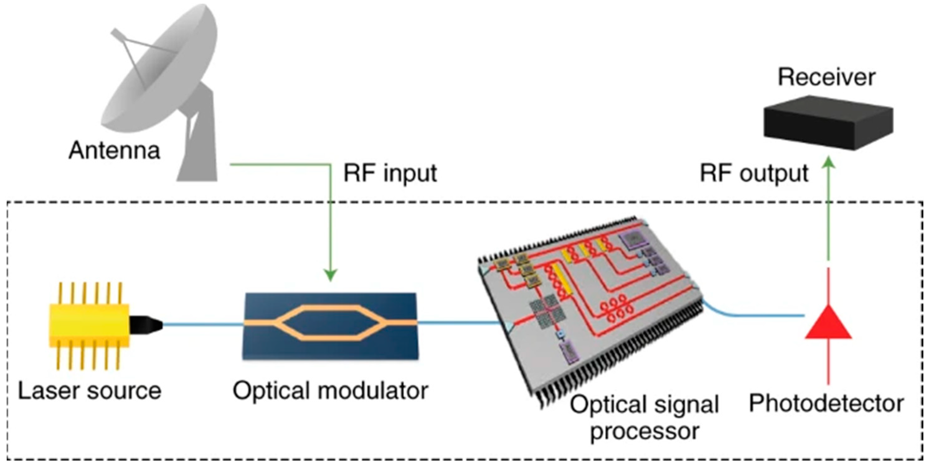
Figure 1. Schematic diagram of the microwave photonic link. Courtesy of [8].
Photonics 10 01110 g001
Figure 2. Comparison of traditional RF filter and MPF. (a) Schematic diagram of the traditional microwave filter. (b) Schematic diagram of the MPF. c.w.: continuous wave. Courtesy of [6].
Photonics 10 01110 g002
Figure 3. Schematic diagram of microwave filters.
Photonics 10 01110 g003
Figure 4. The typical amplitude frequency response of an FIR-MPF.
Photonics 10 01110 g004
Figure 5. (a) Schematic diagram of the FIR-MPF. EOM: electro-optical modulator. (b) FBG-based implementation of FIR-MPF with different delay times. PM: phase modulator. Courtesy of [46].
Photonics 10 01110 g005
Figure 6. (a) Schematic diagram of the IIR-MPF. Courtesy of [46]. (b) IIR-MPF used an optical variable delay line (OVDL). MZM: Mach–Zehnder modulator; EDFA: erbium-doped fiber amplifier; SOA: semiconductor optical amplifier; TNOF: tunable narrowband optical filter. Courtesy of [50].
Photonics 10 01110 g006
Figure 7. Schematic diagram of the cascaded IIR-MPFs. (a) An IIR-MPF consisting of two cascaded active RDL loops. ATT: attenuator; TDL: tunable delay line; TOF: tunable optical filter. (b) Amplitude frequency response of the MPF. Courtesy of [54].
Photonics 10 01110 g007
Figure 8. IFM based on FIR-MPF and IIR-MPF. (a) Schematic diagram of the IFM system. (b) Measured and simulated amplitude frequency responses. (c) Measurement error versus the input frequency. Courtesy of [64].
Photonics 10 01110 g008
Figure 9. OEO based on FIR-MPF and IIR-MPF. (a) Schematic diagram of the OEO based on cascading an IIR-MPF and an FIR-MPF. (b) Measured amplitude frequency response of the cascaded MPFs. (c) Frequency tunability of the OEO. (d) Correlation of the oscillation frequency and the wavelength spacing. PC: polarization controller; FD-POP: Fourier-domain programmable optical processor; HNLF: highly non-linear fiber; OC: optical coupler; EA: electrical amplifier; SSA: signal source analyzer. Courtesy of [18].
Photonics 10 01110 g009
Figure 10. (a,b) Amplitude frequency responses of (a) the positive coefficient MPF with coefficients of (1, 1, 1, 1, 1, 1) and (b) the negative coefficient MPF with coefficients of (1, −1, 1, −1, 1, −1). Courtesy of [71].
Photonics 10 01110 g010
Figure 11. Implementations of negative coefficient MPF. Courtesy of [16]. (a) Schematic diagram of negative coefficient MPF based on XGM in SOA. (b) A negative coefficient MPF with high-frequency selectivity. Courtesy of [85].
Photonics 10 01110 g011
Figure 12. Applications of MPF in microwave frequency measurement. (a) Schematic diagram of the microwave photonic frequency measurement based on a pair of complementary frequency responses of MPF. (b) Measured and calculated frequency responses of the MPF pair and the corresponding ACF. (c) Measurement errors. Courtesy of [94].
Photonics 10 01110 g012
Figure 13. Applications of MPF in OEO. (a) Schematic diagram of the OEO based on an ultra-narrow passband MPF. TLD: tunable laser diode; TOBF: tunable optical bandpass filter; OTDL: optical tunable delay line; ESA: electrical spectrum analyzer. (b) Measured amplitude frequency response of the cascaded MPFs. (c) Frequency tunability of the OEO. Courtesy of [19].
Photonics 10 01110 g013
Figure 14. Schematic diagram of coherent MPFs. (a) A frequency-tunable MPF based on a PS-FBG. Courtesy of [97]. (b) A single passband coherent MPF based on cascaded FBGs. Courtesy of [98].
Photonics 10 01110 g014
Figure 15. Schematic diagram of the incoherent MPF. (a) Phase inversion in MZMs. Courtesy of [99]. (b) Negative coefficients obtained by counter phase modulation in MZM. Courtesy of [1].
Photonics 10 01110 g015
Figure 16. MPFs with an ultra-high rejection ratio. (a) The topology of the microwave photonic notch filter with an ultra-high rejection ratio based on DPMZM. (b) Measured frequency response of the MPF (red dashed line) and conventional SSB filter. (c) Measured frequency tunability of the MPF. DPMZM: dual-parallel Mach–Zehnder modulator. Courtesy of [94]. (d) The schematic diagram of the SOI-based device. (e) The principle of implementing ultrahigh peak rejection. (f) Measured optical spectra of DSB, SSB, and optical bandpass filter. (g) Measured frequency responses of the MPF under different operation conditions. (h) Measured frequency tunability of the MPF. Courtesy of [106].
Photonics 10 01110 g016
Figure 17. The bandwidth of IMPF is reduced by increasing the Q factor of MRR. (a) Schematic diagram of the ultrahigh-Q MRR. (b) Microscope image of the fabricated ultrahigh-Q MRR. (c) Simulated light propagation in the designed 180°-Euler MWB and the mode profile at the input and output ports. (d) Measured result of the resonator with the Lorentzian-curve fitting. (e) Measured frequency response of the IMPF. (f) Experimental results of the frequency tunable IMPF from 3.4 to 19.3 GHz. (g) The measured center frequency of the IMPF as the temperature varies. Courtesy of [129].
Photonics 10 01110 g017
Figure 18. Schemes of single-bandpass MPF. (a) Schematic diagram of the MPF based on phase-compensated SOI MRR. (b) Measured microwave filter response without and with phase compensation. (c) Tunable MPF frequency response. Courtesy of [130].
Photonics 10 01110 g018
Figure 19. The shape factor and rejection ratio of the single-passband MPF are improved. (a) Schematic diagram and illustration of the single-passband MPF based on a double-notch filter. (b) Measured RF responses of the single-passband MPF. (c) Measured frequency tunability of the MPF. Courtesy of [116].
Photonics 10 01110 g019
Figure 20. MPFs with flexible tunability and reconfigurability. (a) Structure of the 10th-order MRR. (b) Optical transmission spectrum from GC2 to GC3. (c) Measured frequency responses of the MPF with different bandwidths. GC: grating coupler. Courtesy of [131]. (d) The schematic diagram of four cascaded MRRs. (e) Measured and simulated frequency responses with different bandwidths. The center frequency of the MPF variation when the FWHM bandwidth is set as 0.7 GHz (f) and 2 GHz (g). Courtesy of [107].
Photonics 10 01110 g020
Figure 21. MPFs based on programmable structure. (a) Schematic diagram of the SOI-based four-tap FIR filter. (b) Measured frequency tunability of the MPF. (c) Measured bandwidth reconfigurability of the MPF. (d,e) Measured reconfigurability of amplitude response. Courtesy of [26]. (f) Schematic diagram of the hexagonal waveguide mesh. (g) Fabricated chip based on SOI. (h) An 8-BUL UMZI and its amplitude responses. (i) A 6-BUL CROW and its amplitude responses. BUL: basic unit length. Courtesy of [27].
Photonics 10 01110 g021
Figure 22. MPF based on DFBR. (a) Schematic diagram of the SOI-based DFBR MPF. MH: micro-heater; LH: long heater. (b) DFBR spectral reflectivity for passband window tuned in the Bragg wavelength. (c) Details of the passband window. (d) Measured frequency tunability of the MPF with a 5 GHz bandwidth. (e) Tuning characteristics of the MPF for reconfigurable bandwidth values of 10 GHz. Courtesy of [135].
Photonics 10 01110 g022
Figure 23. Optical APFs based on SOI. (a) The APF realized by using MRR-coupled MZIs. (b,c) Measured amplitude and phase frequency responses of the microwave photonic phase shifter based on fabricated APF, respectively. Courtesy of [91]. (d) The APF realized by using MZI-assisted MRR. (e,f) Measured amplitude and phase frequency responses of the APF, respectively. Courtesy of [92].
Photonics 10 01110 g023
Figure 24. The full IMPF. (a) The image of a monolithically integrated photonic chip. (b) Image of the packaged chip. (c) Measured frequency responses of the bandpass MPF. Courtesy of [157].
Photonics 10 01110 g024
Figure 25. IMPF based on SOI. (a) Schematic diagram of the IMPF. (b) Image of the fabricated device. (c) Schematic diagram of the thermally tunable high-Q MDR. (d) Measured amplitude frequency responses of the MPF under different heater power consumptions. Courtesy of [169].
Photonics 10 01110 g025
Figure 26. A hybrid integrated MPF. (a) Schematic diagram of the hybrid integrated MPF. (b) Image of the packaged MPF. (c) Measured amplitude frequency responses of the band-stop filtering. (d) Measured amplitude responses of the bandpass filtering. (e) Measured amplitude responses when the InP laser is turned off and turned on, respectively. Courtesy of [105].
Photonics 10 01110 g026
Figure 27. Applications of IMPF in OEO. (a) Schematic diagrams of the SOI chip. (b) Measured amplitude frequency response of the MRR-based MPF. (c) Measured electrical spectrum when the MPF and PT-symmetry breaking are combined in OEO. (d) Measured electrical spectrum with different oscillation frequencies of the PT-symmetric OEO. Courtesy of [20]. (e) Schematic diagram of the integrated OEO based on SBS. (f) Measured electrical spectrum of the OEO. (g) Frequency tunability demonstration of the OEO. Courtesy of [21].
Photonics 10 01110 g027
Figure 28. Applications of IMPF in microwave photonic frequency measurement. (a) Schematic diagram of the FTPM frequency measurement. (b) Measured MPF responses for different wavelengths. (cd) Theoretical and measured ACF12 and ACF13, respectively. (e) Measurement range and error for different wavelengths. Courtesy of [24]. (f) Schematic diagram of the FTTM frequency measurement. (g) The corresponding waveform diagram at points A, B, C, D, and E marked in (f). (h) The resonant mode of the MDR. (i) The fitted relationship between time difference and microwave frequency. (j) Measured frequency and the corresponding error. Courtesy of [178].
Photonics 10 01110 g028
Table 1. Performance comparison of reported IMPFs.
PlatformFilter
Type
FWHM
Bandwidth
(GHz)
Tunable
Range
(GHz)
Rejection
Ratio
(dB)
Gain
(dB)
Noise
Figure
(dB)
SFDR *
(dB/Hz2/3)
RF [103]Bandpass0.0253–5.640−3.13.1137
As2S3 [104]Band-stop30–15>40−10.127.196.5
InP [81]Bandpass1.9–5.40–2732N/A23.286.3
InP + SOI [105]Bandpass/
Band-stop
0.36–0.47/
0.38–0.45
3–21/
3–25
>10/
>40
−28.251.299.7
SOI [106]Band-stop0.780–4060N/AN/AN/A
SOI [107]Bandpass0.7–5.22–35.8518.973390.1
Si3N4 [108]Band-stop0.15–0.350–1250815.6116
* SFDR: Spurious Free Dynamic Range.
Disclaimer/Publisher’s Note: The statements, opinions and data contained in all publications are solely those of the individual author(s) and contributor(s) and not of MDPI and/or the editor(s). MDPI and/or the editor(s) disclaim responsibility for any injury to people or property resulting from any ideas, methods, instructions or products referred to in the content.