Article

A Data Generation Method for Image Flare Removal Based on Similarity and Centrosymmetric Effect

State Key Laboratory of Extreme Photonics and Instrumentation, Zhejiang University, Hangzhou 310027, China
*
Author to whom correspondence should be addressed.
Photonics 2023, 10(10), 1072; https://doi.org/10.3390/photonics10101072
Submission received: 18 July 2023 / Revised: 17 August 2023 / Accepted: 14 September 2023 / Published: 22 September 2023

Abstract

:
Image pairs in under-illuminated scenes along with the presence of complex light sources often result in strong flare artifacts in images, affecting both image quality and the performance of downstream visual applications. Removing lens flare and ghosts is a challenging issue, particularly in low-light environments. Existing methods for flare removal are mainly restricted by inadequate simulation and real-world capture, resulting in singular categories of scattered flares and unavailable reflected ghosts. Therefore, a comprehensive deterioration procedure is crucial for generating a dataset for flare removal. We propose a methodology based on spatial position relationships for generating data pairs with flare deterioration, which is supported by theoretical analysis and real-world evaluation. Our procedure is comprehensive and realizes the similarity of scattered flares and the symmetric effect of reflected ghosts. We also construct a real-shot pipeline that respectively processes the effects of scattering and reflective flares, aiming to directly generate data for end-to-end methods. Experimental results demonstrate that our methodology adds diversity to existing flare datasets and constructs a comprehensive mapping procedure for flare data pairs. Our method facilitates the data-driven model to achieve better restoration in flare images and proposes a better evaluation system based on real shots, thus promoting progress in the area of real flare removal.

1. Introduction

Photographs taken in scenes with strong light sources often exhibit lens flare, which is a prominent visual artifact caused by unintended reflections and scattering within the camera. These flare artifacts can be distracting, reduce the level of image detail, and obscure image content. Severe flare often disrupts the imaging process, preventing users from obtaining the desired image. Additionally, flare can interfere with subsequent computer vision tasks, leading to significantly increased error rates in tasks such as registration, segmentation, detection, and recognition. Even though significant efforts have been made in the optical design of lenses to minimize lens flare, both consumer cameras and expensive professional film lenses can still produce a substantial amount of flare when exposed to unsuitable light sources.
The pattern of lens flare depends on various factors, such as the optical characteristics of the lens, the lens protection glass, the infrared cut-off glass, the position and intensity of the light source, manufacturing defects, scratches, and dust that accumulates through daily use. Due to the diversity of these causes, lens flares can manifest in a variety of ways, including halos, streaks, bright lines, saturated spots, reflections, haze, and more as shown in Figure 1. This complexity makes removing flare a challenging problem.
Most current methods for generating lens flares do not take into account the physical factors that cause flares, including the relative positions of objects and light sources that contribute to the flare effect. Instead, these methods rely on flare templates and intensity thresholds to synthesize data. These flare templates are often generated from laboratory shots, which means they can only detect and potentially remove a limited number of flare types, and do not work well in more complex real-world scenarios.
Despite various methods for generating data in the field of flare removal, the main challenge remains the lack of training data. Collecting data requires outdoor nighttime static scenes with completely unchanged imaging positions and the constant switching of imaging devices. One method for generating no-flare and flare images involves switching lenses [2], which requires post-registration and is labor-intensive. Other researchers have manually placed an occluder between the light source and the camera [3], but this method is also labor intensive and difficult to compensate for the central light source. Due to the complex causes of lens flare, even changing lenses or blocking light sources cannot guarantee that new images will be completely free of flare.
To overcome this challenge, we propose to generate real-world datasets using purely optical methods. Specifically, we will create datasets based on our prior knowledge of optical physics and the three-dimensional relationships of objects in physical space.
To address scattering situations, such as scratches, dust, oil, and other defects, we propose a method that takes into account the similarity effect of scattered flare in multi-light source scenes. We believe that the scattered flare formed by light spots in different areas of a scene maintains a similar appearance. Additionally, we reproduce a real-world data collection method that is fast, does not require registration, retains the central light source, and is not limited by the camera lens parameters. Compared to previous work on similar data collection, our real dataset is specifically designed to capture the similarity effect of scattered flare. Furthermore, we develop an optical point spread function (PSF) calibration plate to demonstrate the similarity effect of diffuse lens flares through theoretical derivation and device experiments. To account for the similarity effect of multi-light source scenes in real-world images, we use a data augmentation technique on our simulated data. We demonstrate the effectiveness of these improvements through experiments on our dataset and with our network.
For reflection cases, such as lens reflections and protective glass reflections, we propose a method to remove the reflection flare without changing the lens. Based on real-world experiments and analysis of optical lens models, we find that reflection flares are often symmetrical to the center of the main light source. Furthermore, due to the centrosymmetric effect, the position of the reflected light spot often differs from the displacement direction of the subject when the camera moves. Using 3D reconstruction and super-resolution methods, we can obtain batches of reconstructed images without reflection flares by inputting batches of images with reflection flares. We also apply the centrosymmetric effect of reflected flares to the construction of simulated data. We discuss the existence of the centrosymmetric effect of flare through theoretical derivation and image analysis. We demonstrate the effectiveness of this improvement through experiments on our datasets and with our network.
To demonstrate the effectiveness of our new real-world dataset, data augmentation, synergy, and centrosymmetric effects, we retrain two different neural networks [4,5] that were originally designed for other tasks. We ensure the same training conditions, do not perform special optimization or parameter adjustments, and focus solely on the effect of the data and the proposed methods. Both subjective and objective evaluations demonstrate the effectiveness of our approach. We use our real-world dataset for subjective and objective evaluation of the network’s ability to remove flare.
In summary, we make several innovations in the field of image flare removal:
  • Based on the principles of Fourier optics, we propose the similarity effect of scattering flare. The effectiveness of this principle has been demonstrated through both theoretical analysis and optical experiments.
  • Based on the similarity effect of scattering flare, we propose a real-world dataset of scattering flare with multiple light sources
  • Based on the principles of optical lens design, we propose the central symmetry effect of reflective flare.
  • Based on the centrosymmetric effect of reflective flare, we propose a real-world dataset for removing reflective flare based on three-dimensional reconstruction.
  • We apply the similarity effect of scattering flare and the centrosymmetric effect of reflective flare in the generation of simulated data, enabling the network to achieve better anti-flare effects after training.

2. Related Work

2.1. Single Image Flare Removal

Hardware solutions for flares usually involve complex optical designs and materials to reduce the occurrence of flares. Anti-reflective coatings are applied to lens components to minimize internal reflections. However, these coatings can only be optimized for specific wavelengths, and the constantly changing working length and incident angle of the lens make it difficult to achieve a perfect solution. In addition, adding a coating to an optical surface can be expensive. Therefore, many post-processing techniques have been proposed to remove flares.
In addition, there have been many studies focused on developing specialized optical imaging structures to reduce flares. One approach that researchers initially explored involved capturing flare-free data by inserting structured occlusions [6]. However, this approach often resulted in artifacts and only provided limited improvement in image signal-to-noise ratio. Another approach involves placing an array of filters on the sensor to obtain specific spectral information, which can then be used to remove flare [7].
A variety of digital processing methods are employed to address flares in HDR photography [8]. However, these methods largely rely on the assumption of a point spread function (PSF), which can vary spatially, leading to inaccurate results. Other solutions [9,10] use a two-stage process involving the detection of flares based on their unique shape and position, and the image degradation they cause. However, these solutions are only applicable to certain types of flares and can mistakenly classify all bright areas as flares. In reality, images contaminated by flares resemble a local haze, and the perception and recovery of data information obscured by this haze are the key focus.
Several machine learning-based methods have been proposed for removing flares, including those described in [3,11,12,13]. These methods are capable of removing flares during the day or flares with specific pattern types.
Some researchers have applied methods from other image-processing tasks to single-frame flare removal, including dehazing [14], removing reflections [15], and denoising [9]. These methods attempt to decompose an image into normal (ground truth) and flare parts, effectively separating the image into two layers. The performance of these networks largely depends on the quality of the training dataset. While there have been many efforts focused on generating flare datasets, there is still much room for improvement. Additionally, some researchers have proposed a method for removing flare by using multiple images to reconstruct the original camera flare scene from multiple apertures, assuming that the depths of the scene and the occlusion layer are known. This method requires two images if the depth is known and three images if the depth is unknown [16].
Recently, a new method called Flare7K++ [17] was proposed, which complements the approach presented in this paper. According to the replication results, the Flare7K [2] dataset, which consists of reflective flare data, was captured in a laboratory setting and lacks the diversity found in our dataset. The subjective comparison of different types of existing deflare image data is shown in the Figure 2. The network trained on Flare7K is able to perceive most of the diffuse and reflective flare components but still struggles to completely eliminate flare. The replication results of Flare7K++ better ensure the stability of light source textures and colors after flare removal. Additionally, a workshop on image flare removal was held at ECCV [18], where multiple groups showcased their respective flare removal algorithms. Some researchers also explored processing data in the raw domain following the approach of Flare7K [19]. Furthermore, the researchers of Flare7K++ proposed a method for capturing reflective flare using different exposure levels and achieved certain results in reflective flare removal [20]. However, these data-driven methods were conducted in a simulated environment, and there is still a significant gap between them and real-world scenarios.

2.2. NeRF-Based View Rendering

The neural radiance field (NeRF) [21] is an implicit MLP-based model that maps 5D vectors—3D coordinates plus 2D viewing directions to opacity and color values, computed by fitting the model to a set of training views. NeRF++ [22] aims to address the ambiguity problem in image reconstruction within NeRF and introduces a novel spatial parameterization scheme. PixelNeRF [23] can achieve similar results with fewer images. NGP [24] uses hash coding and other acceleration methods to greatly speed up the computation of neural radiance fields.
In addition to reducing the number of required images and computation overhead, there are variations of NeRF-type algorithms for specific areas. BlockNeRF [25] focuses on street view generation, MegaNeRF [26] focuses on large-scale images, WildNeRF [27] focuses on image fusion in different exposure ranges, and DarkNeRF [28] focuses on low illumination at night.
We believe that NeRF can be used not only for view interpolation and three-dimensional (3D) reconstruction but also as a data generation tool. In 3D space, many challenging 2D image problems can be easily solved. By feeding batches of speckle images into 3D reconstruction and rendering, we can obtain batches of new speckle-free images. These new images are automatically stripped of information that does not correspond to a 3D position, such as reflective flares that we want to remove.

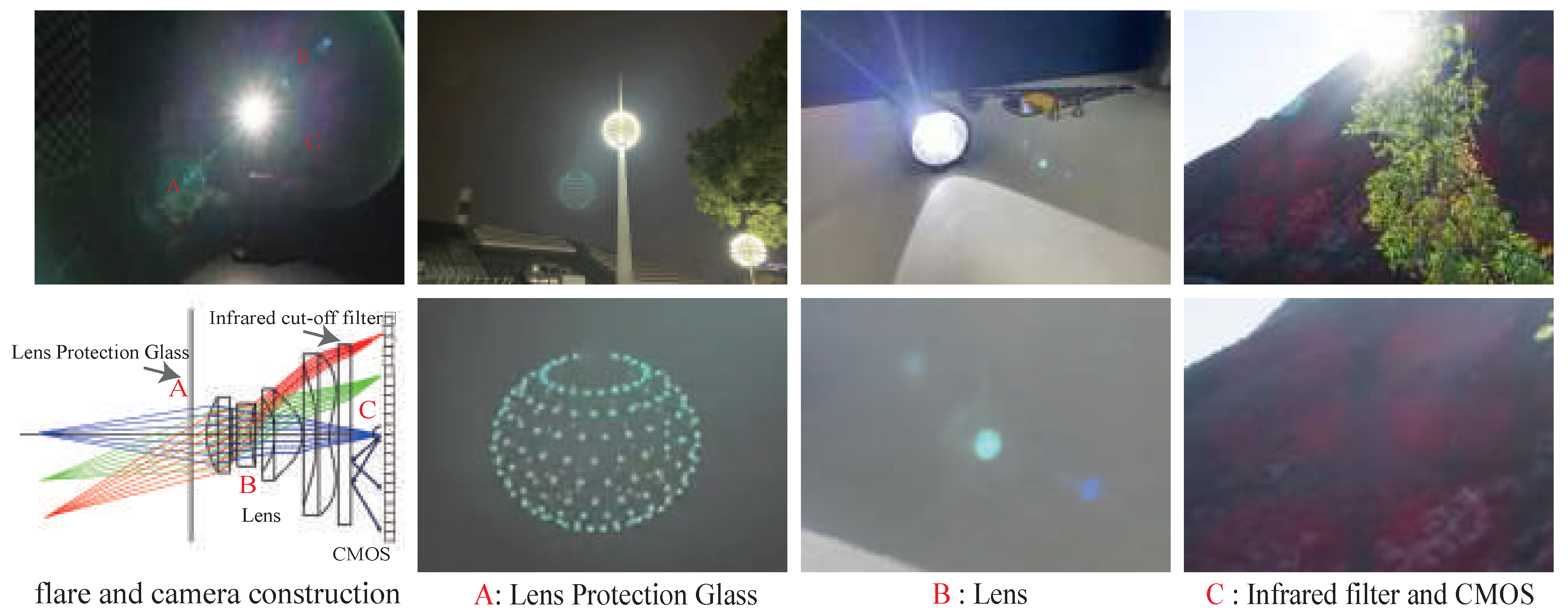
3. Physics of Lens Flare

In an ideal lens design, a cluster of rays should converge on the sensor along the normal operating path after multiple refractions. However, in real-world scenes with high light ratios, light can scatter along unintended paths, causing flare. The actual image surface will receive scattered and reflected light along unintended paths, leading to unwanted artifacts in the image as shown in Figure 3. Scattering and reflection are always present in the optical imaging model, but the scattered and reflected portion is typically a small fraction of each incident light ray. Therefore, they may not be detectable in most photographs.
In this section, we first explain the physical mechanisms of different types of flares, which are mainly divided into two categories: scattering and reflecting flares. We then introduce the challenges of existing single-image flare removal methods.

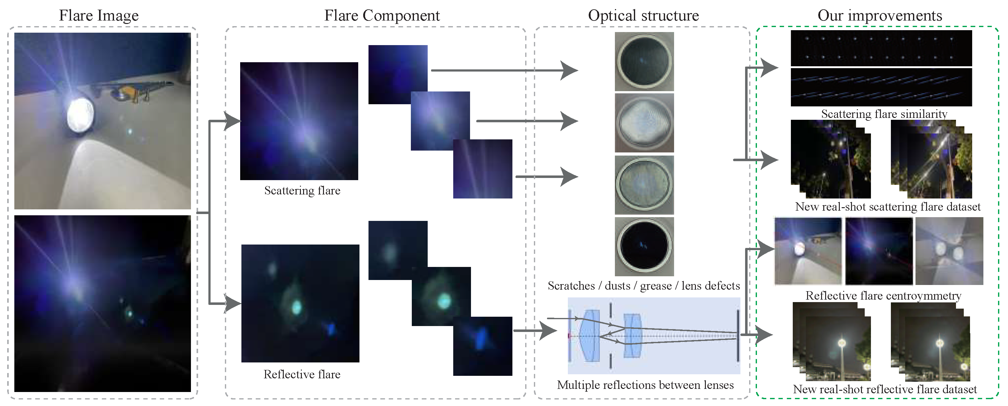
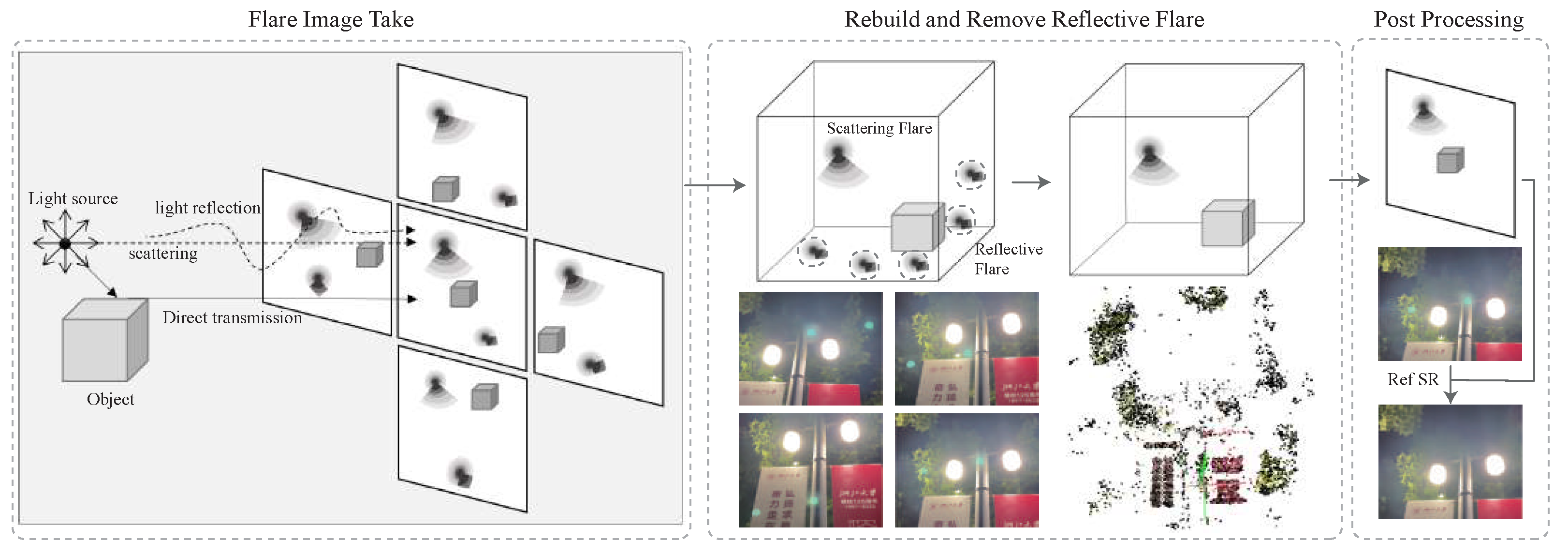
3.1. Scattering Flare

Dust, scratches, and grease in manufactured lenses can introduce diffraction to the incident light, causing rays to scatter or diffract along unintended paths, leading to image degradation. Dust can add an iridescent effect, while scratches can create one or more streaks of rays originating from the light source. Scattering can also reduce the contrast in the area around the light source.

3.2. Reflective Flare

In practical lens systems, a small amount of reflection occurs at each air–glass interface. After an even number of reflections, the direction of light propagation changes slightly, and sometimes the light still reaches the image plane. Since the number of air–glass interfaces is twice that of the number of lenses, there are more opportunities for reflection flares to occur.
In the spatial distribution of reflective flares, the optical path is symmetric due to the circular aperture. In the image, these reflective flares are usually located in a straight line connecting the light source and the center point. They are sensitive to the angle of incidence of the light source. The distribution of reflective flares is related to the field of view. The reflective flare is also limited by the mechanical structure of the lens, such as the aperture. Part of the structure can block the light path of the reflected flare, leading to arcing artifacts.
In the spectrum distribution, reflection flare also behaves differently on different spectra. Due to the different lens transmittance of different wavelengths of light, the camera lens suffers from chromatic aberration. At the same time, to reduce the reflection of air–glass spacing and improve the transmittance, the lens surface is commonly coated with an optical coating. However, this coating responds differently to different spectral bands. So the color of the reflected flare varies a lot and is difficult to simulate.
It is important to note that there are two commonly overlooked cases of reflected flare: reflections from protective glass and CMOS reflections caused by IR-cut glass [1]. Reflections from protective glass often produce flares that are symmetrical to the light source, resulting in over exposure and loss of image information. However, the reflective flare produced by protective glass often exhibits more complex texture changes of the light source, offering a new avenue for restoring image information. The reflection flare caused by IR-cut glass CMOS occurs when light hits the CMOS, is diffracted by the periodic circuit structure on the CMOS, and is then reflected back from the IR-cut glass. This type of reflection flare can also be observed and should be taken into consideration when analyzing the image.

4. Proposed Method

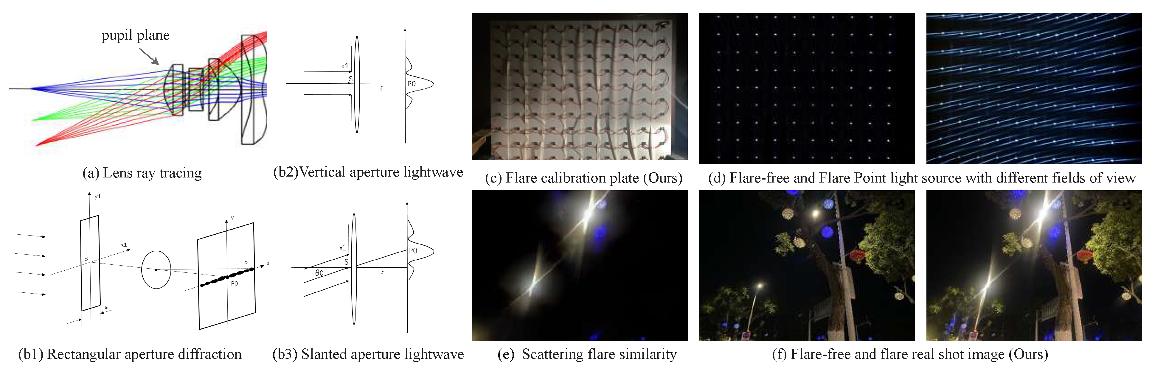
4.1. Scattering Flare Similarity

In a typical consumer-level camera, the pupil plane is located on the first surface of the lens. As a result, light entering from different angles is equally affected by the polluted entrance pupil. Therefore, light sources from different fields of view produce similar flare results as shown in Figure 4. It is worth noting that when light passes through an imperfect lens, diffraction can occur, resulting in a diffraction pattern in the far field. This phenomenon can be described using the far-field Fraunhofer diffraction formula.
E = C A f exp ( i k f ) exp i k x 2 + y 2 2 f Σ E ˜ x 1 , y 1 exp i k l x 1 + ω y 1 d x 1 d y 1 ,
Here, the term C A f exp ( i k f ) represents the phase delay from S to P as indicated in Figure 4(b1–b3). The intensity distribution of the incident light on the diffraction plane, denoted as E ˜ x 1 , y 1 , is the same as the intensity distribution on the aperture of a camera. The term exp i k l x 1 + ω y 1 represents the phase difference between each point relative to the center point of the entrance pupil.
Based on this formula, the structure of the first surface functions as a physical Fourier transform operator to generate the scattering flare.
A damaged lens that causes scattering can be modeled as a complex diffraction element. In a given scene, there may be various light sources with different positions and intensities. The complex amplitude from different fields of view (FoVs) can be represented as
E θ = E 0 exp i 2 π x 1 sin θ 0 λ ,
where θ 0 represents the angle between the incident direction and the optical axis of the camera, and λ represents the wavelength of light. This representation of complex amplitude corresponds to a plane wave that is inclined to the diffraction aperture plane in the spatial domain. The spatial inclination is equivalent to a linear phase shift in the Fourier domain, which can be expressed as follows:
E θ = E 0 exp i 2 π x 1 u 0 ,
where the translation amount u 0 can be expressed as
u 0 = x 0 λ f = sin θ 0 λ ,
Due to Fraunhofer diffraction of the incident light source, Fourier transformation is required. When the aperture is illuminated with a tilted plane wave, it causes a shift in the diffraction results. This conclusion is known as the phase shift theorem of the Fourier transform, which states that a spatial displacement in the time domain corresponds to a phase shift in the frequency domain. The specific formula is given as follows:
F f x 1 exp i 2 π u 0 x 1 = F u u 0 ,
where F represents the Fourier transform. The shape of the frequency domain F ( u u 0 ) remains unchanged, with only a horizontal shift occurring. The change in the central position still conforms to the geometrical optics.
Based on the formula derivation above, scattering caused by the same point light source in different image fields is similar. Although the size, brightness, and color of the scattering flare may vary due to the different colors and intensities of the light source, the shape of the scattering image and its spectrum remain similar. To demonstrate the similarity of scattering flares from actual shooting, we build an experimental device that can fill the camera’s full field of view with point light sources.
We use various types of degraded lenses to capture scattering flare. As shown in Figure 4d–f, the similarity of scattering flare was maintained throughout the entire field of view. In summary, through theoretical derivation and real-world capture, we demonstrate the similarity effect of scattering flare. This characteristic can be utilized for the generation of datasets.

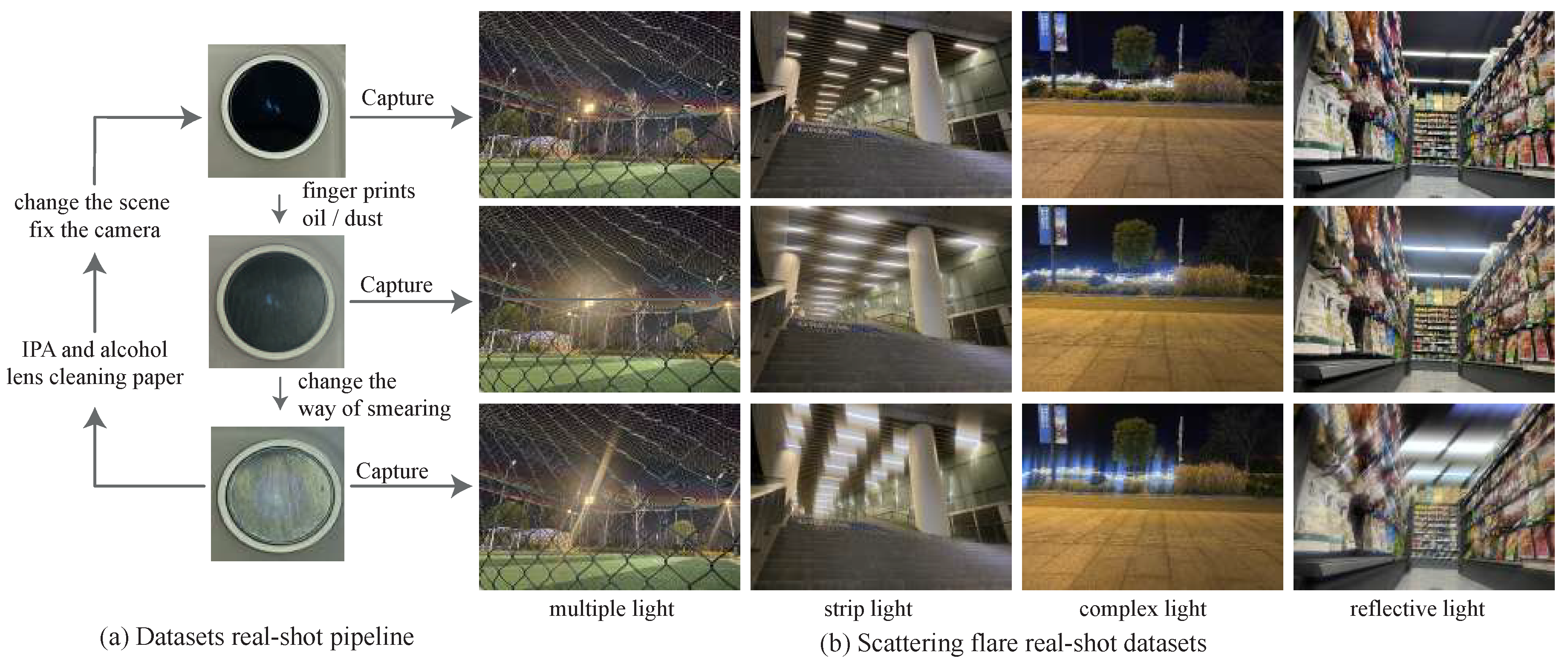
4.2. Scattering Flare Datasets

For ordinary consumer lenses, the pupil plane is often located at the first surface of the camera lens. By continuously degrading and repairing the pupil plane, the desired scattering flare data can be obtained.
Figure 5 illustrates our process for capturing scattered flares, which mainly consists of the following steps:
(1)
Wipe the protective glass with isopropylamine (IPA) and a cleaning cloth.
(2)
Find a suitable shooting position where a light source in the scene will produce some flare, and hold the camera steady.
(3)
Take pictures of the ground truth.
(4)
Spread oil and dust onto the protective glass to degrade the pupil plane.
(5)
Take pictures of the flare caused by the degraded pupil plane.
(6)
Repeat steps 4 and 5 continuously to obtain multiple sets of scattered flare images, and return to step 1 to clean the protective glass and start the process again.
Due to the influence of slight lens flare defects on the ground truth, it is not possible to completely avoid the evaluation of paired real-world data. Therefore, it can only serve as a reference and may not fully reflect the actual performance of lens flare removal methods. However, compared to existing real shot datasets, our real scattered flare dataset has several advantages, including a larger quantity of data, more diverse forms of light sources, more light sources, and a smaller ground truth flare effect.
For the simulation dataset, we use the Optical Flares plugin in Adobe AE to generate data, similar to what Flare7K does. However, we improve the scattering synergistic effect and central symmetry effect in data generation. In night scenes, compared to daylight flares, there are often multiple light sources. Therefore, we first generate multiple light sources of random size and position, and then generate the corresponding flare size and position based on the position and size of the light sources. The generated flares have a similar appearance but different positions and sizes, which conform to the scattering flare similarity effect in the real world.

4.3. Reflective Flare Centrosymmetry

Reflective flare components are challenging to simulate using rendering techniques due to their dependence on an accurate description of the optics [29,30]. However, the unpredictability of reflective flare is often exacerbated by the lack of available lens prescriptions. Fortunately, most existing optical lenses are centrally symmetric, meaning that the flare data are distributed along the axis of symmetry of the light source, regardless of its position relative to the camera. Moreover, lenses with similar designs tend to exhibit similar internal reflections. Data collected from one camera example can be used to model lenses with similar designs or applications.
Reflective flare is closely related to the structure of the light source, and natural scenes offer a wide range of lighting conditions to study. However, the limited range of artificial light sources makes it difficult to capture comprehensive reflective flare datasets in the laboratory. Additionally, the structure of reflected flares varies across different fields of view (FoV). Therefore, it is necessary to capture reflective flare components from various angles by moving the camera to ensure a comprehensive dataset.

4.4. Reflective Flare Datasets

Flare7k [2] is a software tool that can simulate dynamic reflective flare effects. In this tool, the opacity of the flare component is set to be proportional to the distance between the aperture and the light source. To demonstrate the clipping effect of the aperture on reflective flare, the algorithm erases part of the flare when the distance between the reflective flare component and the clipping threshold is greater than the threshold.
Simulation data are advantageous due to their low cost. However, a disadvantage of this approach is the limited number of simulated reflection flares. The availability of only a limited number of lenses and light sources in the laboratory makes it impossible for simulated data to accurately capture the variety of reflection flare scenes that can occur in the real world.
Based on the centrosymmetric effect, we also make improvements to the existing simulation method for reflective flares. Typically, reflective flare templates are based on laboratory experiments and have a consistent direction, such as a 45-degree oblique direction. However, we modify this approach by constraining the positions of the scattered flare and light source to be on the central symmetry line of the reflective flare. We then randomly rotate the entire flare template by a certain angle to put it into the clean image.
We propose a reflective flare removal method based on 3D reconstruction, the brief process is shown in Figure 6. As the camera’s position changes, the light source and reflective flares in the image also change. Reflective flares are symmetrical with respect to the center of the light source, with different flares generally distributed on the central axis of symmetry. Additionally, the displacement of reflective flares is also symmetrical with respect to the light source. As a result, the displacement changes of reflective flares do not conform to the laws of 3D reconstruction, which means that the reconstructed image will not have any reflective flares.
The formula for 3D reconstruction is as follows:
r ( t ) = o + t d ,
where r ( t ) represents the sampled ray, o represents the sampled ray emission point, and t represents the displacement along the ray direction d . Let σ ( r ( t ) ) denote the differential probability of the infinitesimal particle, where the light ray terminates at position t. The color of this sampled ray is determined by integrating from the near boundary t n to the far boundary t f . The integration result is given by the following expression:
C = ( r , g , b ) = t n t f T ( t ) σ ( r ( t ) ) c ( r ( t ) , d ) d t ,
where c represents the pixel value of the voxel at the corresponding position of t. T ( t ) represents the cumulative transmission rate along the ray from t n to t, which is the probability that the ray propagates from t n to t without being blocked:
T ( t ) = exp t n t σ ( r ( s ) ) d s ,
In a three-dimensional scene, objects and light sources are typically stationary. However, due to the centrosymmetric effect of reflective flares, changes in the camera pose result in significant variations in the spatial distribution of reflective flares, which do not correspond to the camera pose change. As shown in the middle part of Figure 6, when all the information is input into the three-dimensional space, the reflective flare appears at various positions in the space. The probability of occurrence at each position is the reciprocal of the entire dataset, and the sum of the probabilities of all positions is equal to one. Since the flare occasionally blocks certain sampling rays, the color in this area must change. By applying the derivation in NeRF [21], the integration can be discretized in the calculation process. Specifically, we assume that the specular flare is blocked at positions t i to t i 1 . In this case, the formula should be adjusted as follows:
C i = ( r i , g i , b i ) = t n t i 1 T ( t ) σ ( r ( t ) ) c ( r ( t ) , d ) d t + t i 1 t i T ( t ) σ ( r ( t ) ) c ( r ( t ) , d ) d t + t i t f T ( t ) σ ( r ( t ) ) c ( r ( t ) , d ) d t ,
When the reflective flare is added to the sampling ray from t i to t i 1 , it leads to changes in the transparency σ ( r ( t ) ) and color c in the integral from t i 1 to t i . The color σ ( r ( t ) ) , transparency c , and transmission rate T ( t ) in the range from t n to t i 1 are also changed.
The formula presented earlier represents only the rendering process of the neural radiance field network. In actual network training, only two types of parameters are involved: σ ( r ( t ) ) and c . Since the flare C i only appears once at the same position, the probability of C i is much smaller than that of C . When the network starts training and converges, the optimal solution will be close to a large number of flare-free σ ( r ( t ) ) and c . The erroneous parameters of the flare part will be automatically discarded to achieve the goal of removing the flare. It is worth noting that there are many improved versions of NeRF, which often use image encoding features to improve the performance of NeRF. However, these methods often do not perform well in fitting reflective flare, as the encoding feature tends to pay more attention to the interference of reflective flares.
Compared to capturing reflected flare images in a laboratory setting, our data generation method enables the acquisition of datasets using any lens, imaging device, and scene. This approach significantly enhances the diversity and reliability of the data while also reducing the overall difficulty of collection. Moreover, it eliminates the complexities associated with both flare and image fusion.
Compared to previous datasets, the data obtained by our method accurately capture the degradation process of reflection-type flare for various light source imaging distances and various FoVs. Three-dimensional reconstruction also requires a significant number of images captured from multiple angles, and the dataset for reflective flares similarly demands a substantial number of images taken from different angles. The requirements for both methods are perfectly aligned.
During nighttime situations, various LED lights with different shapes and brightness levels are common and may result in reflected light spots with varying shapes and textures, such as Figure 7. Previously, there was no effective way to handle these complex scenarios, but our method can automatically handle these challenging situations. Compared to previous datasets, our designs more accurately represent real-world nighttime conditions.

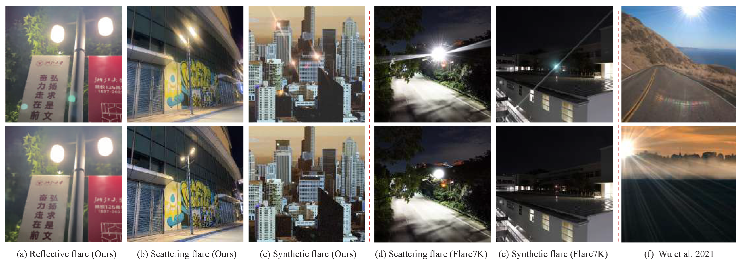
4.5. Comparison with Existing Flare Dataset

The benchmark flare datasets proposed by Wu [3] and flare7K [2] were designed for removing flares during both daytime and nighttime scenarios. In Wu’s pipeline [3], flares are primarily caused by stains on the lens surface. Wu’s method collects real-world flares by simulating various pupil functions. However, the simulated pupil functions and actual complex lens damage exhibit significant differences, resulting in a diversity and accuracy gap between synthetic flares and real-world scenes.
The simulation component of the Flare7K dataset primarily employs AE simulation plug-ins but does not consider the physical phenomena that cause lens flare generation, such as the flare similarity and centrosymmetry effects. Although the simulation cost is low and the speed is fast, there are still significant disparities between the simulated and actual flares.
The Wu method [3] includes very few real-world images, which are all based on a single light source and do not account for the similarity effect of diffuse flare. Additionally, in order to capture reflected glare spots in these images, the main light source is often placed outside the field of view, resulting in a lack of light source in the actual shot dataset and preventing the centrosymmetric effect from being represented.
The scatter-type real-shot data in Flare7K are obtained using various cameras and lenses, and the resulting images are then registered, leading to high costs and a smaller data volume. The real-world shooting data do not take into account multi-light source scenarios. Furthermore, the Flare7K dataset lacks a real-world reflective flare dataset, making it impossible to evaluate the effectiveness of reflective flares.
Table 1 demonstrates that our dataset is more comprehensive in terms of quantity, the similarity effect, and the central symmetry effect, whether it comprises simulated data or real-world data. Additionally, further details about the contents, including 5000 × 5 , are introduced in the next section.

5. Experimental Results

5.1. Simulation Data Evaluation

To showcase the effectiveness of our approach, we trained two widely used neural networks, each with a distinct architecture that was previously employed in other image restoration tasks. By utilizing our proposed method, both networks yielded commendable results. Notably, all network configurations were based on the fundamental structure that is publicly available for each network.
We trained Restormer [5] and Uformer [4] using our synthetic dataset. To evaluate the efficacy of the dataset and our proposed similarity and centrosymmetric effects, we employed the same network and parameters. Our primary focus was on comparing the deflare results obtained using different data generation methods. We used sharp images from the Flickr dataset [31], while scattered and reflected flare images were provided by Flare7K. The synthetic dataset includes five different variants, as shown by 5000 × 5 in Table 1. Furthermore, the ground truth (GT) is divided into two categories with or without central light source information, resulting in a total of ten variations. To ensure fairness in network training, we utilized the same hardware and training time, and the training dataset consisted of 5000 × 512 × 512 pixels image pairs. The specific definitions of these data variants, shown in Figure 8, are as follows:
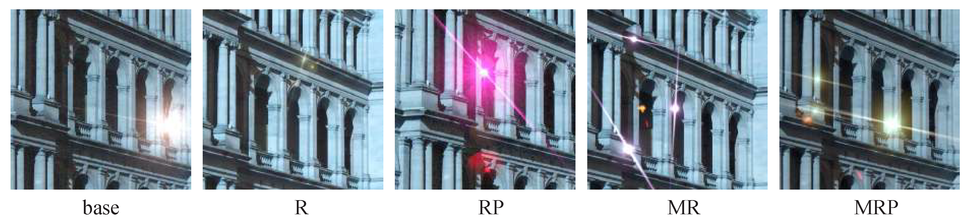
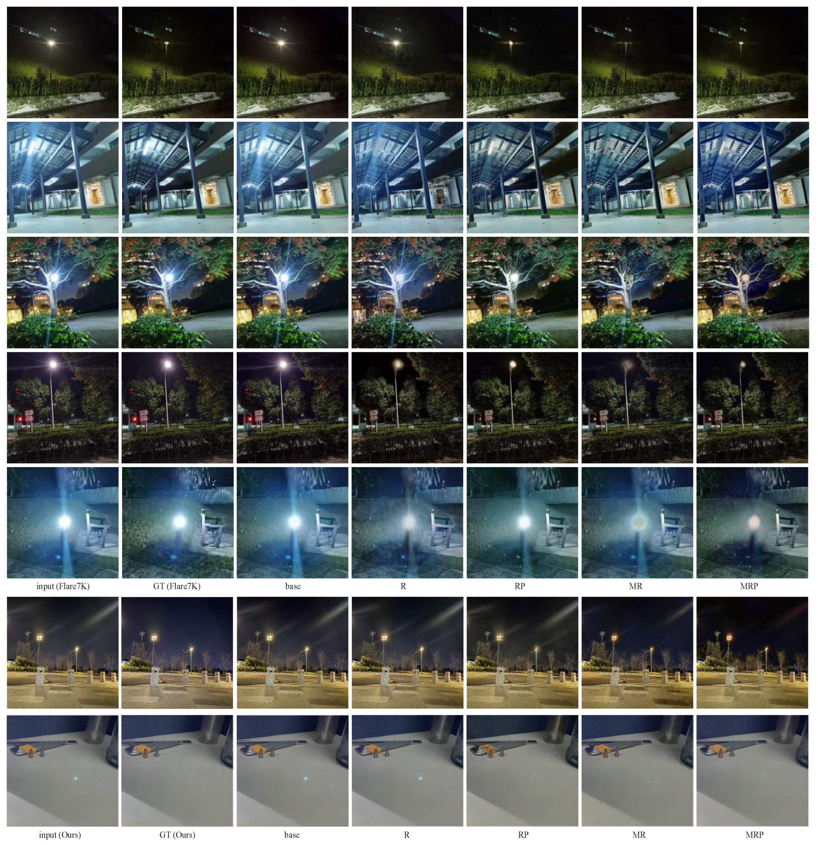
  • Base: added scattering flare same to Flare7K.
  • R: added scattering and reflective flare same to Flare7K.
  • RP: with added scattering flare and reflective flare based on centrosymmetric effect.
  • MR: with added scattering flare based on similarity effect and reflective flare.
  • MRP: with added scattering flare based on similarity effect and reflective flare base on centrosymmetric effects.
  • w/o L. the ground truth image without a light source, the flare should be removed first before adding the light source.
As shown in Table 2, the performance of the two networks is similar in our dataset. There is no specific evaluation metric for flare removal in the field of image processing. Therefore, we adopted commonly used evaluation metrics from the image-processing domain for objective assessment. Specifically, we used the peak signal-to-noise ratio (PSNR) [32] and the structural similarity index measure (SSIM) [33]. Our proposed method demonstrates superior performance compared to other methods in terms of PSNR and SSIM scores. Keeping the light source in GT preserves data that can train a better-performing network. Therefore, our later discussions are mainly based on the dataset that preserves the light source in GT. Simply added reflective flare may result in only a small improvement. However, increasing reflective flare based on the central symmetry effect can further enhance the network performance. Compared with dataset R, dataset MR increases the scattering flare. Flare number augmentation can further improve the network’s fitting ability. Compared with dataset RP, dataset MRP increases the scattering flare based on the similarity effect, which is a much greater improvement than the data augmentation from dataset R to dataset MR. Compared with dataset MR, dataset MRP maintains the same amount of scattering flare but introduces similarity effects, leading to improved training results. In summary, our experiments on the simulation dataset confirm that adding light sources in GT, increasing the number of scattering flares, and adding reflective flares, based on similarity and central symmetry effects, can all further improve network performance.

5.2. Real Shot Data Evaluation

Since the flare area can occupy a non-uniform portion of the image area, many image metrics (such as PSNR, SSIM, and LPIPS) can yield high objective scores even in the absence of flare removal. Removing the flare can result in a slight degradation of non-flare areas and potentially impact the overall image metrics. Therefore, it is critical to employ a range of real-world shooting data for subjective testing and comparison.
The upper half of Figure 9 displays the test results obtained using Flare7K real-world shooting data, whereas the lower half shows the outcomes produced by our own real shooting data using the same network training. From top to bottom, the results demonstrate the superiority of our dataset over the existing Flare7K dataset. Our real shooting data feature smaller flares, more complex light sources, and better handling of reflective flares. However, our real shooting dataset still exhibits some degree of flare, which necessitates further refinements to address it effectively.
We also identified some limitations of the Flare7K dataset. Firstly, the flare in the provided ground truth is still discernible and not entirely convincing as a test benchmark. Additionally, as can be observed from the last line of the Flare7K section in Figure 9, it not only features severe scattering flare but also fails to capture the effects of reflective flare. The reflective flare in the ground truth is indistinguishable from that in the input image.
As illustrated in Figure 9, moving from left to right, we can observe a substantial improvement in the subjective evaluation of network results stemming from changes in the training dataset. In the upper half of Figure 9, we compare our results to those obtained using the latest Flare7K real-world shooting dataset. The experimental subjective results are in complete agreement with our dataset improvement direction. Under the same training time, existing methods, such as the dataset base, yielded relatively poor results, and the flare removal effect was not significant. Dataset R, which added reflective flare, exhibited improved suppression ability compared to the dataset base, but the removal ability of scattering flare was not significantly enhanced. For example, in the bottom row of the Flare7K section in the upper half of Figure 9, a blue reflective flare is present, and the removal of reflective flare using dataset base, dataset R, and dataset RP improves progressively. Increasing the number of flares had a limited effect on removing scattering flares. The results of dataset MR show the possibility of eliminating the light source entirely.Dataset MR also had minimal impact on the reflective flare. However, dataset MRP, which combines all our data enhancements, more effectively removed scattering flare and reflective flare. For instance, as shown in the lower half of Figure 9, the dataset MRP results can remove most of the scattering flare while preserving the approximate shape of the light source. Simultaneously, they can also suppress the blue reflective flare in the last row.
The experimental results obtained using dataset MRP demonstrate a significant improvement in handling both scattering and reflective flare compared to the ground truth (GT) of existing real-world shooting datasets. As the benchmark real-world shooting datasets, the GT urgently requires improvements. Otherwise, it would be difficult to evaluate the effectiveness of the network’s deflare results.
The lower half of Figure 9 shows the network testing that we conducted using our real-world shooting data. The training outcomes for removing scattering flare using dataset base, dataset R, and dataset RP were average. However, using dataset MR substantially enhanced the flare removal results. By incorporating the scattering flare similarity effect, dataset MRP yielded excellent outcomes in removing scattering flare. Subjectively, the results of dataset MRP are even better than those of the ground truth image.
We generated our own real-world shooting reflective flare dataset, which enables us to subjectively evaluate the image quality of reflective flare removal. Although the bottom row of Figure 9 displays only the reflective flare portion of the image, both the actual shooting image and network processing strictly adhere to the centrosymmetric effect. Similar to Figure 7, the image was cropped to better showcase the details. As obtaining a scattering flare dataset is relatively mature, our dataset was designed solely to evaluate the removal of reflective flare. Since the network handles both scattering and reflective flare, it was necessary to remove the scattering flare portion to compare the reflective flare removal ability. As shown in the bottom row of Figure 9, dataset base and dataset R exhibit almost no effect on reflective flare, as all flare still persists. Dataset R randomly adds reflective flare in what appears to be a suboptimal approach and necessitates reflective flare data guided by the centrosymmetric effect to improve its effectiveness. Dataset RP can partly remove reflective flare, but it poorly processes the brightest part, resulting in incorrect black spots. Dataset MR can detect reflective flare, but it processes it poorly overall, leading to a degradation in image quality. Dataset MRP has the best effect and can effectively detect and process reflective flare. Although these data enhancements can gradually improve the network’s ability to remove reflective flare, there is currently a scarcity of reliable datasets with light sources for evaluating this aspect. Since our real-world shooting datasets can be entirely free of any trace of reflective flare, they can serve as reliable and effective test data.

5.3. Dataset Performance Evaluation

In addition to qualitatively comparing the improvements of different real-world shooting datasets on the network’s ability and subjective flare removal results, we also attempted to use objective image evaluation metrics to assess the effects of these datasets. The subjective differences between the various datasets are shown in Figure 2. As shown in Table 3, the Flare7K unreal dataset exhibits faster improvements in objective indicators after enhancement due to its more consistent construction method with the training dataset, which underscores the effectiveness of our enhancement approach. However, this effect is not entirely convincing since Unreal is not a real-world shooting dataset, and the final processing result of the network serves the real world. Therefore, we employed the Flare7K real dataset, which comprises a total of 100 pairs. Compared to the Unreal dataset, our data enhancement on Flare7K real exhibited a more gradual improvement, primarily because there remains a gap between the simulated flare texture and the actual flare. The Flare7K real dataset mostly comprises single-light-source scenes, with only a small proportion featuring multiple light sources as depicted in Figure 2d. This real-world shooting dataset includes scattering flare and very little reflective flare, with the reflective flare remaining unremoved.
Considering the shortcomings of existing real-world datasets, we propose our real-world dataset, which is categorized into scattering flare and reflective flare datasets. These two types of real-shot datasets are not universally applicable. Generating a real-shot dataset with de-reflective flare often proves ineffective in removing scattered flare, while generating a dataset with de-scattered flare may encounter challenges in eliminating reflected flare.
For the scattering flare dataset, we focused more on including different colored light sources, a larger number of lights, and various light shapes as depicted in Figure 5. The new real-world dataset for scattering flare also highlights the improvements achieved through our data enhancement methods. However, the progress is not as significant as that observed in the Flare unreal and Flare real datasets. We believe that this is due to the limited variety of light source types in the simulated dataset, which is not adaptable enough to the various colors and shapes of real-world light sources, resulting in a relatively smaller improvement over the baseline. The more gradual increase in test result indicators also provides room for the evaluation of future new work, and future improvements can be reflected in our real-world scattered dataset.
For the reflective flare real-world dataset, the objective image evaluation only compares the image portion of the reflective flare, with the scattering flare portion cropped and removed. Due to the reduced image resolution, the evaluation indicators improve significantly, and we only need to focus on the improvement between different data enhancement methods. Compared to the dataset base, dataset R’s randomly added reflective flare does not enhance the ability to remove reflective flare. It is necessary to increase the center symmetry effect, and then dataset RP can improve the ability to remove reflective flare. The subjective image comparison in the bottom row of Figure 9 also displays the same results. Dataset MR adds multiple scattered light sources and random reflective flare, which can partially remove reflective flare. Our data demonstrate the degradation of reflective flare removal from both subjective images and objective indicators with random multi-light sources and non-centrally symmetric reflective flare data. It also highlights the advantages of dataset MRP in removing reflective flare.

6. Conclusions

Based on the proposed pipeline, most of our flare removal results are satisfactory, with some even surpassing the real-world shooting ground truth images. For a variety of real-world scenes, our new data generation method can improve both subjective and objective indicators. In the generation of simulation data, we demonstrated the similarity effect of scattering flare and the centrality symmetry effect of reflective flare, which is more in line with real-world scenes than existing datasets. Compared to existing real-world shooting data, we also focus on the similar effects of scattering flare and the centrality symmetry effect of reflective flare. Our real-world dataset generation method incurs lower costs and offers more diverse types. By leveraging the characteristics of NeRF, we constructed a reflective flare dataset that can accurately process various types of light sources and reflective flare in complex scenes. Simultaneously, our method enables the separate evaluation of the network’s ability to remove scattering and reflective flare.
However, there are still areas for improvement in single-image flare removal. Firstly, when there is strong scattering or reflection throughout the image, the effect is often not satisfactory, and texture errors can occur in the central light source area. When there is excessive flare in the image, or the light source completely covers the background image information, accurate image decomposition methods cannot be processed perfectly due to the lack of essential information. These limitations stem mainly from the lack of physical information and cannot be resolved simply by improving the dataset. Secondly, the current light source scenes are too complex, and we aim to generate more styles of light sources in the simulation dataset rather than simple point source templates.

Author Contributions

Conceptualization, Z.J.; Software, Z.J.; Writing—original draft, Z.J.; Writing—review & editing, Y.C.; Project administration, H.F. and Z.X.; Funding acquisition, Z.X. All authors have read and agreed to the published version of the manuscript.

Funding

This work is supported by National Natural Science Foundation of China: No. 62275229; Civil Aerospace Pre-Research Project: No. D040104.

Institutional Review Board Statement

Not applicable.

Informed Consent Statement

Not applicable.

Data Availability Statement

Not applicable.

Conflicts of Interest

The authors declare no conflict of interest. The funders had no role in the design of the study; in the collection, analyses, or interpretation of data; in the writing of the manuscript; or in the decision to publish the results.

References

  1. Crocherie, A.; Pond, J.; Gomez, F.D.; Channon, K.; Fantoni, F. Micro to macro scale simulation coupling for stray light analysis. Opt. Express 2021, 29, 37639–37652. [Google Scholar] [CrossRef] [PubMed]
  2. Dai, Y.; Li, C.; Zhou, S.; Feng, R.; Loy, C.C. Flare7K: A Phenomenological Nighttime Flare Removal Dataset. Adv. Neural Inf. Process. Syst. 2022, 35, 3926–3937. [Google Scholar]
  3. Wu, Y.; He, Q.; Xue, T.; Garg, R.; Chen, J.; Veeraraghavan, A.; Barron, J.T. How to train neural networks for flare removal. In Proceedings of the IEEE/CVF International Conference on Computer Vision, Montreal, BC, Canada, 11–17 October 2021; pp. 2239–2247. [Google Scholar]
  4. Fu, Y.; Liu, Y.; Li, J.; Luo, D.; Lv, S.; Jv, Y.; Xie, L. Uformer: A unet based dilated complex & real dual-path conformer network for simultaneous speech enhancement and dereverberation. In Proceedings of the ICASSP 2022—2022 IEEE International Conference on Acoustics, Speech and Signal Processing (ICASSP), Singapore, 22–27 May 2022; pp. 7417–7421. [Google Scholar]
  5. Zamir, S.W.; Arora, A.; Khan, S.; Hayat, M.; Khan, F.S.; Yang, M.H. Restormer: Efficient Transformer for High-Resolution Image Restoration. In Proceedings of the 2022 IEEE/CVF Conference on Computer Vision and Pattern Recognition (CVPR), New Orleans, LA, USA, 18–24 June 2022. [Google Scholar]
  6. Talvala, E.V.; Adams, A.; Horowitz, M.; Levoy, M. Veiling glare in high dynamic range imaging. ACM Trans. Graph. (TOG) 2007, 26, 37-es. [Google Scholar] [CrossRef]
  7. Sassoon, E.; Schechner, Y.Y.; Treibitz, T. Flare in interference-based hyperspectral cameras. In Proceedings of the IEEE/CVF International Conference on Computer Vision, Seoul, Republic of Korea, 27 October–2 November 2019; pp. 10174–10182. [Google Scholar]
  8. Reinhard, E.; Ward, G.; Pattanaik, S.N.; Debevec, P.E.; Heidrich, W. High Dynamic Range Imaging: Acquisition, Display, and Image-Based Lighting; Morgan Kaufmann: Burlington, MA, USA, 2010. [Google Scholar]
  9. Asha, C.; Bhat, S.K.; Nayak, D.; Bhat, C. Auto removal of bright spot from images captured against flashing light source. In Proceedings of the 2019 IEEE International Conference on Distributed Computing, VLSI, Electrical Circuits and Robotics(DISCOVER), Manipal, India, 11–12 August 2019; pp. 1–6. [Google Scholar]
  10. Vitoria, P.; Ballester, C. Automatic Flare Spot Artifact Detection and Removal in Photographs. J. Math. Imaging Vis. 2019, 61, 515–533. [Google Scholar] [CrossRef]
  11. Qiao, X.; Hancke, G.P.; Lau, R. Light Source Guided Single-Image Flare Removal From Unpaired Data. In Proceedings of the International Conference on Computer Vision, Montreal, BC, Canada, 11–17 October 2021. [Google Scholar]
  12. Sun, Q.; Tseng, E.; Fu, Q.; Heidrich, W.; Heide, F. Learning Rank-1 Diffractive Optics for Single-Shot High Dynamic Range Imaging. In Proceedings of the 2020 IEEE/CVF Conference on Computer Vision and Pattern Recognition (CVPR), Seattle, WA, USA, 13–19 June 2020. [Google Scholar]
  13. Feng, R.; Li, C.; Chen, H.; Li, S.; Loy, C.C.; Gu, J. Removing diffraction image artifacts in under-display camera via dynamic skip connection network. In Proceedings of the IEEE/CVF Conference on Computer Vision and Pattern Recognition, Nashville, TN, USA, 20–25 June 2021; pp. 662–671. [Google Scholar]
  14. Song, Y.; He, Z.; Qian, H.; Du, X. Vision Transformers for Single Image Dehazing. IEEE Trans. Image Process. 2023, 32, 1927–1941. [Google Scholar] [CrossRef] [PubMed]
  15. Li, C.; Yang, Y.; He, K.; Lin, S.; Hopcroft, J.E. Single Image Reflection Removal Through Cascaded Refinement. In Proceedings of the 2020 IEEE/CVF Conference on Computer Vision and Pattern Recognition (CVPR), Seattle, WA, USA, 13–19 June 2020. [Google Scholar]
  16. Gu, J.; Ramamoorthi, R.; Belhumeur, P.; Nayar, S. Removing image artifacts due to dirty camera lenses and thin occluders. In ACM SIGGRAPH Asia 2009 Papers; ACM: New York, NY, USA, 2009; pp. 1–10. [Google Scholar]
  17. Dai, Y.; Li, C.; Zhou, S.; Feng, R.; Luo, Y.; Loy, C.C. Flare7K++: Mixing Synthetic and Real Datasets for Nighttime Flare Removal and Beyond. arXiv 2023, arXiv:2306.04236. [Google Scholar]
  18. Dai, Y.; Li, C.; Zhou, S.; Feng, R.; Zhu, Q.; Sun, Q.; Sun, W.; Loy, C.C.; Gu, J.; Liu, S.; et al. MIPI 2023 Challenge on Nighttime Flare Removal: Methods and Results. In Proceedings of the IEEE/CVF Conference on Computer Vision and Pattern Recognition, Vancouver, BC, Canada, 17–24 June 2023; pp. 2852–2862. [Google Scholar]
  19. Lan, F.; Chen, C.W. Tackling Scattering and Reflective Flare in Mobile Camera Systems: A Raw Image Dataset for Enhanced Flare Removal. arXiv 2023, arXiv:2307.14180. [Google Scholar]
  20. Dai, Y.; Luo, Y.; Zhou, S.; Li, C.; Loy, C.C. Nighttime smartphone reflective flare removal using optical center symmetry prior. In Proceedings of the IEEE/CVF Conference on Computer Vision and Pattern Recognition, Vancouver, BC, Canada, 17–24 June 2023; pp. 20783–20791. [Google Scholar]
  21. Mildenhall, B.; Srinivasan, P.P.; Tancik, M.; Barron, J.T.; Ren, N. NeRF: Representing scenes as neural radiance fields for view synthesis. Commun. ACM 2022, 65, 99–106. [Google Scholar] [CrossRef]
  22. Zhang, K.; Riegler, G.; Snavely, N.; Koltun, V. Nerf++: Analyzing and improving neural radiance fields. arXiv 2020, arXiv:2010.07492. [Google Scholar]
  23. Yu, A.; Ye, V.; Tancik, M.; Kanazawa, A. pixelnerf: Neural radiance fields from one or few images. In Proceedings of the IEEE/CVF Conference on Computer Vision and Pattern Recognition, Nashville, TN, USA, 20–25 June 2021; pp. 4578–4587. [Google Scholar]
  24. Müller, T.; Evans, A.; Schied, C.; Keller, A. Instant Neural Graphics Primitives with a Multiresolution Hash Encoding. ACM Trans. Graph. 2022, 41, 1–15. [Google Scholar] [CrossRef]
  25. Tancik, M.; Casser, V.; Yan, X.; Pradhan, S.; Mildenhall, B.; Srinivasan, P.P.; Barron, J.T.; Kretzschmar, H. Block-NeRF: Scalable Large Scene Neural View Synthesis. arXiv 2022, arXiv:2202.05263. [Google Scholar]
  26. Turki, H.; Ramanan, D.; Satyanarayanan, M. Mega-nerf: Scalable construction of large-scale nerfs for virtual fly-throughs. In Proceedings of the IEEE/CVF Conference on Computer Vision and Pattern Recognition, New Orleans, LA, USA, 18–24 June 2022; pp. 12922–12931. [Google Scholar]
  27. Martin-Brualla, R.; Radwan, N.; Sajjadi, M.S.; Barron, J.T.; Dosovitskiy, A.; Duckworth, D. Nerf in the wild: Neural radiance fields for unconstrained photo collections. In Proceedings of the IEEE/CVF Conference on Computer Vision and Pattern Recognition, Nashville, TN, USA, 20–25 June 2021; pp. 7210–7219. [Google Scholar]
  28. Mildenhall, B.; Hedman, P.; Martin-Brualla, R.; Srinivasan, P.P.; Barron, J.T. Nerf in the dark: High dynamic range view synthesis from noisy raw images. In Proceedings of the IEEE/CVF Conference on Computer Vision and Pattern Recognition, New Orleans, LA, USA, 18–24 June 2022; pp. 16190–16199. [Google Scholar]
  29. Hullin, M.; Eisemann, E.; Seidel, H.P.; Lee, S. Physically-based real-time lens flare rendering. In ACM SIGGRAPH 2011 Papers, Proceedings of the SIGGRAPH ’11: Special Interest Group on Computer Graphics and Interactive Techniques Conference, Vancouver, BC, Canada, 7ߝ11 August 2011; ACM: New York, NY, USA, 2011; pp. 1–10. [Google Scholar]
  30. Lee, S.; Eisemann, E. Practical real-time lens-flare rendering. In Computer Graphics Forum; Wiley Online Library: New York, NY, USA, 2013; Volume 32, pp. 1–6. [Google Scholar]
  31. Zhang, X.; Ng, R.; Chen, Q. Single image reflection separation with perceptual losses. In Proceedings of the IEEE Conference on Computer Vision and Pattern Recognition, Salt Lake City, UT, USA, 18–22 June 2018; pp. 4786–4794. [Google Scholar]
  32. Rabbani, M.; Jones, P.W. Digital Image Compression Techniques; SPIE Press: Bellingham, WA, USA, 1991; Volume 7. [Google Scholar]
  33. Wang, Z.; Bovik, A.C.; Sheikh, H.R.; Simoncelli, E.P. Image quality assessment: From error visibility to structural similarity. IEEE Trans. Image Process. 2004, 13, 600–612. [Google Scholar] [CrossRef] [PubMed]
Figure 1. Types and locations of flare. (A) A specially captured lab image with predominantly different types of flare. (B) A schematic diagram showing the location of flare in the lens structure, based on the optical structure from [1]. (C) Illustration of various types of reflective flare, corresponding to the ABC labels in the previous images.
Photonics 10 01072 g001
Figure 2. Comparison of different deflare datasets. (f) note the existing real-shot dataset lacks suitable ground truth. (d,e) note that neither the real-shot dataset nor the simulation dataset can accurately restore the color and shape of the light source, and the flare does not conform to real-world conditions. (c) note the simulation dataset we propose considers the multi-light source situation and takes into account the similar scattering flare caused by different position light sources for the same lens and centrally symmetric reflected flare. (a,b) note our real-shot dataset. Our real-shot dataset can capture complex multi-light source scenes well and can accurately capture data on reflection-type flares [2,3].
Photonics 10 01072 g002
Figure 3. Overview of Flare Causes and Our Improvements. Flare can be divided into two main categories: scattering flare and reflective flare. Each type of flare can be further subdivided based on its specific optical degradation mechanism. We propose improvements for both scattering and reflective flare through simulation and real-shot dataset enhancements.
Photonics 10 01072 g003
Figure 4. Similarity effects of scattering flare. (a) note the typical consumer camera, the aperture plane is located at the first surface of the lens. Light entering the lens from different angles is affected by the same contaminated incident aperture. (b1) note the resulting of rectangular optical diffraction. (b2,b3) note the diffraction results after oblique and vertical incidence. (d) note different light sources in different fields of view may produce slightly different angles of flare. They typically produce similar flare results at the same aperture plane. (c) note the experimental setup for (d). (e) note the real captured images demonstrate the similarity of scattering flare from different light sources. (f) note the data pairs for the image (e).
Photonics 10 01072 g004
Figure 5. Real-world scattered flare dataset. (a) note actual shooting process and the changes to the camera’s protective glass (pupil surface) during the data collection. (b) note various types of non-flare and flare images captured in our dataset. Compared to existing real-world shooting datasets, our dataset pays more attention to the shape and quantity of light sources, as well as the reflection of objects. To reduce the cost of shooting, we adopt a shooting process in which one non-flare image corresponds to multiple flare images.
Photonics 10 01072 g005
Figure 6. Reflective flare data generation pipeline. The process of generating reflective flare data involves shooting multi-angle datasets with reflective flare, followed by 3D reconstruction. Due to the displacement in the distribution of reflective flare in 3D space, reconstruction is not possible. As a result, the output is an image without reflective flare.
Photonics 10 01072 g006
Figure 7. Reflective flare real shot dataset. (a) note images with reflective flare from different angles in the dataset. (b) note the optical flow information from different angles. Due to the central symmetry effect of reflective flare, the optical flow of reflective flare is significantly different from the normal background. (c,d) note the high-quality data without any reflective flare through 3D reconstruction and the reference super-resolution method.
Photonics 10 01072 g007
Figure 8. Comparison of different types of simulation datasets.
Photonics 10 01072 g008
Figure 9. The test results of different datasets trained on the same network. The top half shows the results of Flare7K’s real captured data, while the bottom half shows our own real captured data. The impact of data improvement on the results can be observed from left to right. The advantages of our dataset compared to existing datasets are reflected from top to bottom. Our real shot image ground truth scattering flares are smaller, the light sources are more complex, and reflective flare is eliminated.
Photonics 10 01072 g009
Table 1. Comparison of the number and characteristics of different datasets in simulation and real shooting. (✓ indicates whether an effect is considered in data generation).
SimulationReal (Benchmark)
DatasetScatteredSimilarityReflectedCentrosymmetryTypeScatteredSimilarityReflectedCentrosymmetry
Wu et al. [3]2000 2000 2 + 1 20 20
Flare7K7000 7000 25 + 10 100
Ours5000 × 55000 × 4 25 + 10 5002000
Table 2. Quantitative comparison of training with different synthetic types of data and testing on existing real flare datasets. (✓ indicates whether a certain effect acts on data generation).
Increase scattering flare
Reflective flare in input
Scattering flare similarity
Reflective flare centrosymmetry
Dataset no light sourcebase w/oLR w/oLRP w/oLMR w/oLMRP w/oL
Restormer (PSNR)24.04 (2.92%)23.45 (10.2%)24.15 (16.2%)24.29 (0.00%)23.91 (4.47%)
Restormer (SSIM)0.905 (4.40%)0.898 (12.1%)0.909 (0.00%)0.907 (2.20%)0.906 (3.30%)
Uformer (PSNR)24.39 (6.41%)24.69 (2.80%)23.13 (23.0%)24.47 (5.44%)24.93(0.00%)
Uformer (SSIM)0.887 (24.2%)0.909 (0.00%)0.854 (60.4%)0.897 (13.2%)0.902 (7.70%)
Dataset Light source in GTbaseRRPMRMRP
Restormer (PSNR)24.15 (12.7%)24.38 (9.77%)24.43 (9.14%)24.45 (8.89%)25.19 (0.00%)
Restormer (SSIM)0.907 (5.68%)0.902 (11.3%)0.912 (0.00%)0.909 (3.41%)0.912 (0.00%)
Uformer (PSNR)24.85 (2.21%)24.88 (1.86%)24.92 (1.39%)24.99 (0.58%)25.04 (0.00%)
Uformer (SSIM)0.910 (25.0%)0.913 (20.8%)0.918 (13.9%)0.917 (15.3%)0.928 (0.00%)
Table 3. Quantitative comparison of training on different synthetic data types and testing on different flare removal datasets. (indicates whether a certain effect acts on data generation).
Scattering flare
Reflective flare
Scattering flare similarity
Reflective flare centrosymmetry
DatasetbaseRRPMRMRP
Flare7K unreal (PSNR)24.52 (22.6%)25.46 (10.0%)24.72 (19.8%)25.76 (6.29%)26.29 (0.00%)
Flare7K unreal (SSIM)0.942 (7.41%)0.944 (3.70%)0.943 (5.56%)0.946 (0.00%)0.936 (18.5%)
Flare7K real (PSNR)24.15 (12.7%)24.38 (9.77%)24.43 (9.14%)24.45 (8.89%)25.19 (0.00%)
Flare7K real (SSIM)0.907 (5.68%)0.902 (11.4%)0.912 (0.00%)0.909 (3.41%)0.912 (0.00%)
Wu’s real (PSNR)21.07 (36.3%)21.52 (29.4%)23.25 (6.05%)23.37 (4.59%)23.76 (0.00%)
Wu’s real (SSIM)0.890 (6.80%)0.892 (4.85%)0.896 (0.97%)0.890 (6.80%)0.897 (0.00%)
Scattering flare real (ours) (PSNR)24.75 (6.66%)24.82 (5.80%)24.79 (6.17%)25.09 (2.56%)25.31 (0.00%)
Scattering flare real (ours) (SSIM)0.916 (6.33%)0.917 (5.06%)0.919 (2.53%)0.921 (0.00%)0.914 (8.86%)
Reflective flare real (ours) (PSNR)33.92 (14.6%)33.76 (16.7%)34.16 (11.4%)27.19 (149%)35.10 (0.00%)
Reflective flare real (ours) (SSIM)0.983 (30.8%)0.983 (30.8%)0.984 (23.1%)0.980 (53.9%)0.987 (0.00%)
Reflective flare real (ours) (LPIPS)0.1412 (18.6%)0.1384 (16.2%)0.1292 (8.48%)0.1569 (31.7%)0.1191 (0.00%)
Disclaimer/Publisher’s Note: The statements, opinions and data contained in all publications are solely those of the individual author(s) and contributor(s) and not of MDPI and/or the editor(s). MDPI and/or the editor(s) disclaim responsibility for any injury to people or property resulting from any ideas, methods, instructions or products referred to in the content.

