Article

Multivariable Analysis of Nonlinear Optical Loop Mirror Operating Parameters Using Jones Matrices and Three-Dimensional Renderings

by
Jose D. Filoteo-Razo
1,
Juan C. Hernandez-Garcia
2,3,*,
Julian M. Estudillo-Ayala
2,
Olivier Pottiez
4,
Jose R. Martinez-Angulo
1,
Jose H. Barron-Zambrano
1,
Juan C. Elizondo-Leal
1,
Vicente P. Saldivar-Alonso
1,*,
Jesus P. Lauterio-Cruz
5 and
Roberto Rojas-Laguna
2
1
Facultad de Ingenieria y Ciencias, Universidad Autonoma de Tamaulipas, Ciudad Victoria 87149, Mexico
2
Departamento de Ingenieria Electronica, Division de Ingenierias Campus Irapuato Salamanca, Universidad de Guanajuato, Carretera Salamanca-Valle de Santiago, Salamanca 36787, Mexico
3
Investigadoras e Investigadores por Mexico CONAHCYT, Consejo Nacional de Humanidades Ciencias y Tecnologias, Benito Juarez 03940, Mexico
4
Centro de Investigaciones en Optica A. C., Loma del Bosque No. 115, Col. Lomas del Campestre, Leon 37150, Mexico
5
Departamento de Investigacion en Fisica, Universidad de Sonora, Hermosillo 83000, Mexico
*
Authors to whom correspondence should be addressed.
Photonics 2023, 10(10), 1071; https://doi.org/10.3390/photonics10101071
Submission received: 18 August 2023 / Revised: 13 September 2023 / Accepted: 21 September 2023 / Published: 23 September 2023
(This article belongs to the Special Issue Recent Advances in Mode-Locked Fiber Laser)

Abstract

:
Nonlinear optical loop mirrors (NOLMs) are used in modern fiber optic devices and optical communications. In this study, we present numerical analyses of the multiple variables involved in the operation of an NOLM in low- and high-power transmissions. The Jones matrix formalism was used to model linear and circular polarization inputs. We used three-dimensional (3D) plots to identify the characteristics required in the experimental operation of the NOLM. These characteristics, including the critical power, low- and high-power transmission, and dynamic range, depend on parameters such as the fiber loop length, input power, angle of retarder plate, and input polarization. A standard single-mode fiber (SMF-28) with high twist loop lengths of 100, 300, and 500 m and input powers of 0–100 W was simulated. Three-dimensional surface graphics provided a comprehensive view of the NOLM transmission and considerably enhanced the optimal transmission by manipulating adjustable device components including the power and polarization control plates. Optimal transmission facilitates its use in integrating ultrafast pulse generation, optical signal processing, optical communication systems, and photonic integrated circuit applications.

1. Introduction

In recent years, the nonlinear optical loop mirror (NOLM) has been applied to ultrafast pulse generation [1,2,3], optical signal processing [4,5], optical communication systems [6,7,8], and photonic integrated circuits [9,10]. Many studies have investigated ultrashort pulse generation using fiber lasers [11,12,13,14,15,16,17,18]. The basic NOLM configuration (power-imbalanced nonlinear fiber Sagnac reflector) does not allow precise control of light polarization within the device [19]. Consequently, determining the evolution of the light polarization because of the random birefringence of the optical fiber is challenging [20]. Therefore, the minimum and maximum transmission positions are affected, and the transmission curve offset moves to a random value, necessitating frequent adjustments of the polarization controller inserted in the loop to maintain the desired transmission characteristics. These adjustments do not allow tuning parameters such as the NOLM switching power and dynamic range (DR) during construction. The advantage of the polarization-imbalanced NOLM configuration over the basic NOLM configuration is that it allows substantial flexibility in controlling the NOLM operating parameters, such as low-power transmission (and transmission slope), switching power, and DR, which critically impact the laser operation and mode-locking regime. These parameters are controlled by adjusting the quarter-wave retarder (QWR) inserted in the loop and the input polarization angle [21,22,23].
In the emission of pulses with complex dynamics generated by a figure-eight laser (F8L), switching is based on nonlinear polarization rotation (NPR) in an NOLM rather than in a ring cavity laser [24,25,26]. In such cases, the NOLM acts as an artificial saturable absorber (SA) [20,27]. The operation of an SA used in a passively mode-locked laser is based on a nonlinear phenomenon such as self-phase modulation (SPM) [28]; this effect induces a differential nonlinear phase shift that accumulates only in case of a power imbalance between beams that propagate clockwise (CW) and those that propagate counterclockwise (CCW) in the loop [29]. Other SAs are based on cross-phase modulation (XPM) [30] or NPR [25], both of which occur in the F8L configuration. Owing to their ultrafast (femtosecond) switching responses and operation-parameter controllability, NOLMs have been successfully used as artificial SAs in F8L architectures [20,22].
NOLMs have been used as frequency comb generators based on a dual-cavity Brillouin random fiber lasing oscillation [31]. NOLMs balance the resonant powers between Stokes and anti-Stokes lines of different orders to achieve lower power deviation. A 2D analysis of the NOLM transmission and input power with fixed-length fiber optics in the NOLM loop was also provided. Transmission adjustments were made through a polarization controller (PC) with three wave plates. The NOLM transmission decreased with the input power upon positioning the PC at different degrees. However, NOLM functions as a power balancer, and it experiences higher losses at higher beam powers. Therefore, achieving the optimum performance for power balancing to ensure efficient laser resonance was difficult.
Previous studies reported using NOLMs for regenerating all-optical amplitude or phase signals in their original state [32,33]. The procedure was based on exploiting linear effects inside the NOLM loop. In this context, a 2D representation was used to analyze the mechanism of phase preservation in the regenerator by addressing the amplitude and phase aspects. This was achieved through adjustments of the PC located inside the NOLM loop.
However, NOLM has not been evaluated using three-dimensional (3D) visualizations. The present study aims to achieve optimal NOLM functionality across diverse application domains. This paper presents the numerical results when transmitting a linearly and circularly polarized input through an NOLM. We investigate the NOLM transmission behavior as a function of variables such as input power and PC. Various transmissions for applications in different fiber optic schemes were simulated. We also demonstrated the potential of an NOLM as an SA in an F8L as a function of several input parameters. As a result, the obtained 3D surface plots and contour maps can improve our understanding of the NOLM system behavior.

2. Numerical Development

Figure 1 shows the NOLM configuration. The design comprises a power-symmetric optical coupler (50/50) and a fiber loop composed of a QWR and a highly twisted low-birefringence standard single-mode fiber (SMF-28) [23]. The QWR is located asymmetrically in the loop, thus breaking the polarization symmetry. The operating principle of an NOLM is based on the interference produced by two counterpropagating waves. This facilitates power-dependent transmission (switching) in the fiber loop. CW and CCW propagating waves must experience different nonlinear phase shifts in the nonlinear medium. This effect results from the Kerr nonlinearities that are intrinsic to the NOLM configurations: SPM and XPM. The interplay of these two modulations results in NPR. Here, a nonlinear phase shift difference arises if the counterpropagating beams have different amplitudes or polarizations; therefore, the polarization states must be different because the amplitude in the present scheme is symmetric owing to the 50/50 coupler. The NOLM configuration allows precise control over the polarization of the two counterpropagating CW and CCW beams. This is because the polarization state of the light within the loop does not change, except for certain rotations along the fiber because of the twist-induced circular birefringence. Thus, ellipticity is conserved during propagation, distinguishing this scheme from conventional NOLMs. The twist results in a precession of the fiber birefringence axes, thereby eliminating residual birefringence. Moreover, a twist allows the polarization asymmetry between the counterpropagating beams to be maintained over the entire loop length, thus facilitating switching. Furthermore, eliminating the residual birefringence, which is strongly affected by environmental conditions, facilitates more stable and predictable NOLM operation. A highly twisted arrangement was adopted to effectively suppress the residual birefringence [34]. In [35], it is experimentally demonstrated that even with moderate torque values (~5 turns/m), ellipticity can be maintained in a standard fiber up to distances of the order of a quarter of a kilometer if a coil with a sufficiently large diameter is used.
The NPR in the fiber loop can be described using the following coupled equations for continuous-wave light [22]:
i z C + = μ 1 2 3 A c P N C + i z C = + μ 1 2 3 + A c P N C ,
where z denotes the first partial derivative with respect to the direction of propagation z , A c = ( C + 2 C 2 ) / ( C + 2 + C 2 ) is a constant during propagation, and μ = π 2 + g 2 ( g = γ π / k ) is the ratio of circular to linear birefringence, where k = π δ n / λ is the linear birefringence, and γ = h / 2 n 1 q is the circular birefringence in the rotating frame [n is the refractive index, h 0.13 0.16 in silica fiber, and q is the fiber twist rate (rad/m)]). Further, P N = β π P / k is the normalized power, where P is the power coupled into the fiber, and β = 4 π n 2 / 3 λ A e f f is the nonlinearity coefficient ( n 2 is the Kerr coefficient, λ is the wavelength, and Aeff is the effective mode area). The two partial differential equations (Equation (1)) are based on the polarization eigenmodes; these are the right and left elliptical polarization states [C+, C]. Owing to the high twist in the fiber loop, the polarization eigenmodes coincide approximately with the circular polarization states [C+, C], and any linear birefringence is omitted. Here, C+ and C are the complex amplitudes of the right and left circularly polarized components, respectively. By solving Equation (1), we obtain a matrix representation of the fiber in the eigenmode basis (Table 1 and Table 2). These equations demonstrate that light propagation through a fiber length can result in two individual nonlinear effects: a nonlinear phase shift and a power- and polarization-dependent rotation of the polarization ellipse [22]. To model the behavior of the NOLM as a whole, each optical element in the system, in Figure 1, was represented by its Jones transfer matrix.
This study adopts a continuous-wave model that allows the modeling of the propagation of polarized light using only the Jones matrices while considering the Kerr effect (SPM as XPM) to obtain an overview of the NOLM performance for a wide range of tuning parameters. A continuous-wave model is not applicable only to continuous light; however, it applies very well in practice in the case of quite long pulses (in which case effects such as loop spread can be neglected). The model does not take into account dispersion and nonlinear Kerr effects in the case of ultrashort pulses (e.g., solitons) or when the peak power of the pulses is very high. The results presented here are not going to be strictly correct. However, they still constitute a good approximation for estimating device operation for a wide range of tuning parameters. If more accurate results are required for any combination of these parameters, the corresponding differential or partial derivative equations (Equation (1)) would have to be solved numerically, including all relevant effects.
The QWR generates an asymmetry in polarization, causing the counterpropagating beams in the fiber loop to have a phase difference, thus enabling switching. This phase difference can be observed in the twisted fiber matrix (FCW/CCW) for each analyzed case. The equations for the nonlinear evolution of polarization (Equation (1)) based on the elliptical polarization and high twist in the loop are considered.
F c w / c c w = e i μ + 1 4 3 A c c w / c c w P i n l 0 0 e i μ + 1 4 3 A c c w / c c w P i n l = e i φ + r c w / c c w 0 0 e i φ r c w / c c w ,
Equation (2) shows a nonlinear phase shift φ = 3 4 P i n l and a polarization-dependent rotation of the ellipse 1 4 A c c w / c c w P i n l that is added to the linear rotation to calculate the total rotation r c w / c c w [22]. Thus, the transfer matrix of the NOLM output E o u t can be determined by calculating the sum of the interfering E o u t C W and E o u t C C W fields at the output. This can be expressed using the Jones matrices for the optical elements defined in Table 1 as:
E o u t C W = 1 2 P i n Q W R C W F C W E i n ,
E o u t C C W = 1 2 P i n F C C W Q W R C C W E i n ,
E o u t = E o u t C W + E o u t C C W ,
The NOLM transmission (T) is represented as follows:
T = E o u t 2 E i n 2
In the case of right circular input polarization, the Jones vector of the input field is expressed as:
E i n = 1 0
By algebraic manipulation of Equations (3)–(6) and referring to the matrices in Table 1, we can determine the Jones vector for the NOLM output. Then, by using Equation (6), the NOLM transmission can be written as:
T = 1 2 1 2 c o s 2 α c o s 1 4 β L P i n + 2 α
where β is related to γ (expressed in W−1 km−1) as γ = 3/2β, L is the NOLM fiber loop length, Pin is the power input, and α is the QWR angle.
In the case of a linear NOLM input polarization, the Jones vector of the input field is
E i n = e i ϕ e i ϕ
where φ is the input polarization angle. From Equations (3)–(6), by algebraic manipulation of the matrices shown in Table 2, we can determine the Jones matrix of the NOLM output. Thus, by using Equation (6), the NOLM transmission can be written as:
T = 1 2 1 2 c o s 1 4 s i n 2 ϕ + 2 α β L P i n 2 α
Equations (8) and (10) are in accordance with previously published research [22,23]. Therefore, these results permit the analysis of the NOLM as an SA in an F8L.

3. Results and Discussion

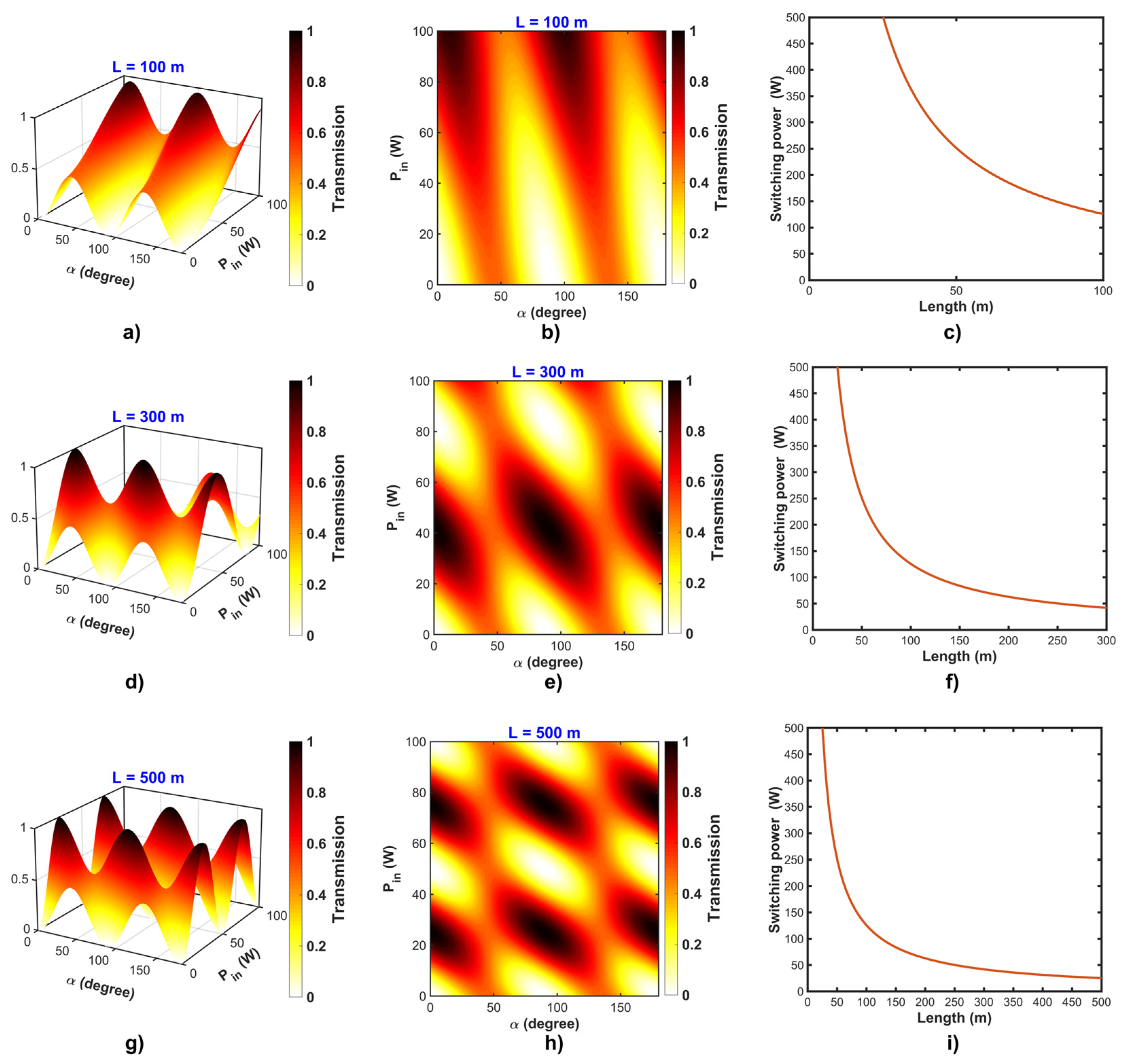
For the present study, we considered linear and circular polarization inputs in NOLM. A standard single-mode fiber (SMF-28) with high torsion was used with the following parameters: β = 1 W−1 km−1 and γ = 1.5 W−1 km−1. In the first case, for circular input polarization, the NOLM transmission is a function of α and Pin (Equation (8)). Figure 2 shows the evolution of the transmission as 3D surface plots and contour maps for fiber loop lengths of 100, 300, and 500 m, and Pin of 0–100 W. Figure 2a,d,h show that the transmission exhibited increasingly sinusoidal behavior with an increase in L. In Figure 2a,b, the transmission starts to increase; specifically, Tmax = 0.6–0.8 (light red) from L = 100 m. After L increases to 300 m (Figure 2d,e) and 500 m (Figure 2g,h), the transmission becomes as high as Tmax = 0.8–1 (dark red to black). By increasing the loop length in the NOLM and adjusting the QWR plate, the nonzero transmission regions (T = 0.1–0.8) enlarge as the power increases. On the contour map, these are indicated by the yellow to black regions, as shown in Figure 2a,b,d,e,g,h. This small increase in the initial transmission (also referred to as initial noise) in the device can be amplified as the light propagates through the NOLM and result in a self-starting characteristic in the pulsed laser [36,37]. As the initial noise is amplified, a precession of modes is initiated, wherein the fluctuations, or amplification noise, are converted into well-defined and stable optical pulses, eventually resulting in laser pulse generation. Consequently, the analysis of this type of polarization in the NOLM loop is highly resistant to polarization-induced disturbances and reduced to phase shift owing to the Kerr effect. This makes NOLMs suitable for applications involving transmitting optical solitons [38].
Another important parameter is the critical power or switching power (Pπ) (Equation (11)) [39,40], defined as the NOLM power corresponding to a nonlinear phase change of π. Figure 2c,f,i show a graphical representation of our investigation into Pπ for the NOLM with circular input polarization. Pπ remains constant as the angle α in the NOLM scheme changes. This value can be modified by changing the loop length in the NOLM; as L increases, Pπ decreases, as shown in Figure 2c,f,i. Another parameter that can be used to modify Pπ is the nonlinearity in the optical fiber. Therefore, the transmission can be switched between two steady states: high and low. The high transmission state allows light to pass through the device, whereas the low transmission state largely blocks light and reflects a large portion of it back to the NOLM input. The control of the switching power is important to ensure optimal operation of the NOLM and to adjust the transmission characteristics according to the specific needs of the application.
Another parameter for studying the NOLM performance is the dynamic range or contrast (DR) (Equation (12)) [22], defined as the ratio between the maximum and minimum transmissions of the device. In the particular case of circular polarization at the input, DR can be adjusted to values between 1 and infinity by rotating the QWR without generating significant changes in Pπ [22]. Thus, DR can be controlled, and the transmission phase can also be adjusted. However, DR is not always minimized when the input power is zero, and DR minimization can be achieved solely by adjusting the QWR.
P π = 4 π β L
D R = T m a x T m i n = 1 s i n 2 ( 2 α ) 2 = 1 2 s i n 2 ( 2 α )
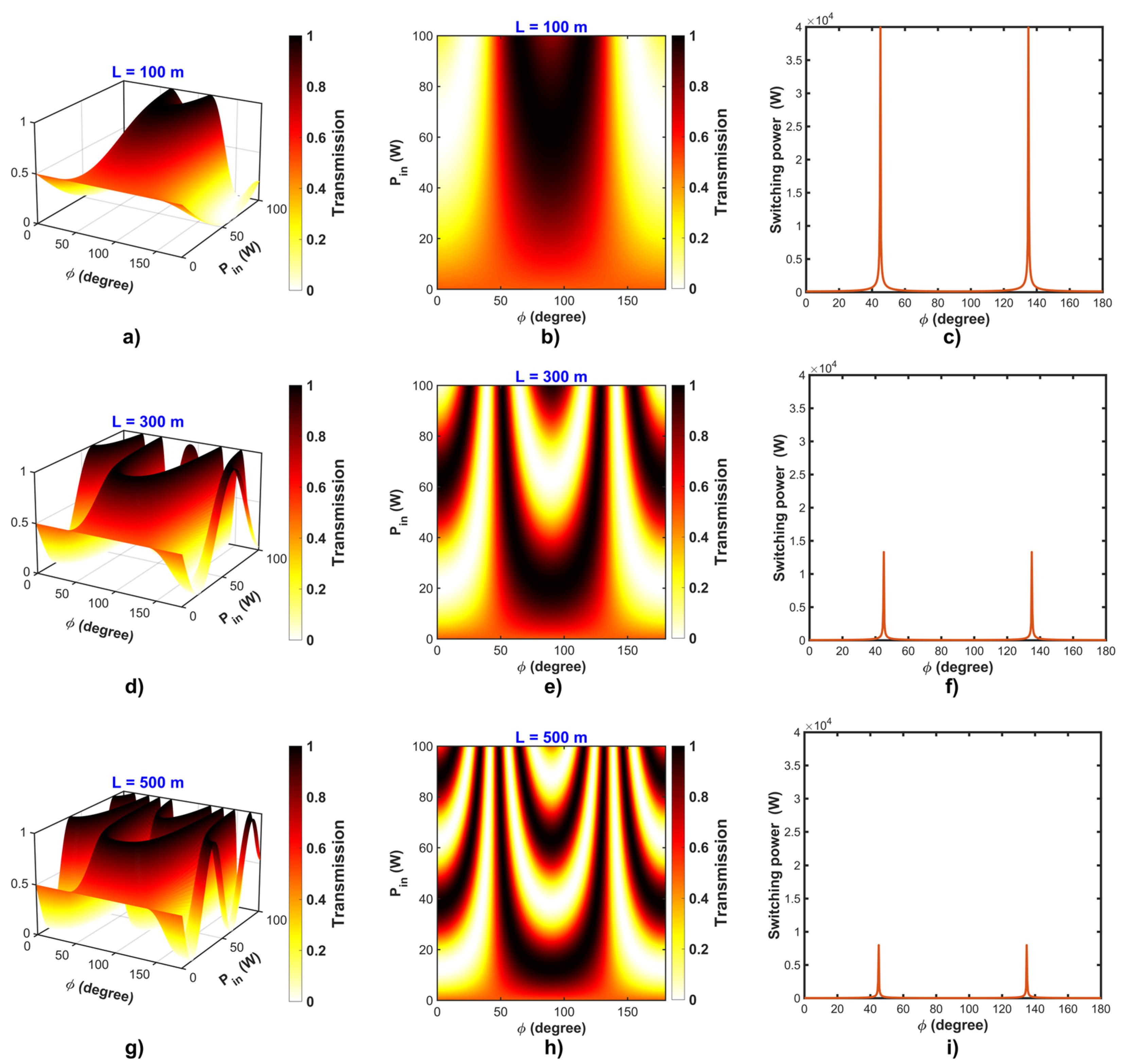
In the second case of linear input polarization, the NOLM transmission is a function of ϕ and Pin, with the QWR angle α set to 45° (Equation (10)). Figure 3 shows transmission as a function of ϕ and Pin for various fiber loop lengths. The results show that high transmission was observed at L = 100 m (light red to dark red) (Figure 3a,b). By increasing the fiber loop to 300 m (Figure 3d,e) and 500 m (Figure 3g,h), more regions of high transmission were obtained for the same ranges of ϕ and Pin. However, a disadvantage of this approach is that the theoretical Pin value can be experimentally affected by losses, efficiency differences, pump power, and other characteristics of the configuration. Equations (13) and (14) yield Pπ and DR for this configuration with linear input polarization. By adjusting α, both Pπ and DR can be modified. However, adjusting Pπ by changing ϕ is more convenient than the adjustment described above for the circular input polarization. In the case of linear input polarization, the minimum value of Pπ was obtained when ϕ = π/4 with respect to the principal axes of the QWR; thus, the CCW beam was circularly polarized (Ac = ±1).
With linear polarization at the input, the fiber optic device is insensitive to polarization changes. This facilitates robust operation by controlling the switchover power with a very high DR. In addition, a higher linearity is achieved by the Kerr effect (NPR) for this type of polarization. Furthermore, a symmetric intensity profile is produced, resulting in a symmetric nonlinear phase shift within the NOLM [41]. This symmetry aids in the realization of stable pulse generation and maintains the pulse quality. These features improve the NOLM performance in applications such as signal processing, pulse compression [42], and pulse repetition rate control [43], and in optical communication systems [44], they facilitate a reduction in the interference between different channels or signals in wavelength division multiplexing systems. In the experimental realization of this scheme, a polarization device (half-wave retarder) was used at the input for polarization manipulation [45]. In Figure 3c,f,i, the maximum Pπ value (infinity) occurred at ϕ = 45° and 135°, corresponding to alignment with the axis of the QWR plate. The advantage of using linear input polarization for the NOLM is that it imparts great flexibility for controlling operating parameters such as transmission, Pπ, and DR.
P π = 4 π s i n 2 ϕ + 2 α β L
D R = T m a x T m i n = 1 1 2 c o s 2 α 2 = 2 1 c o s 2 α
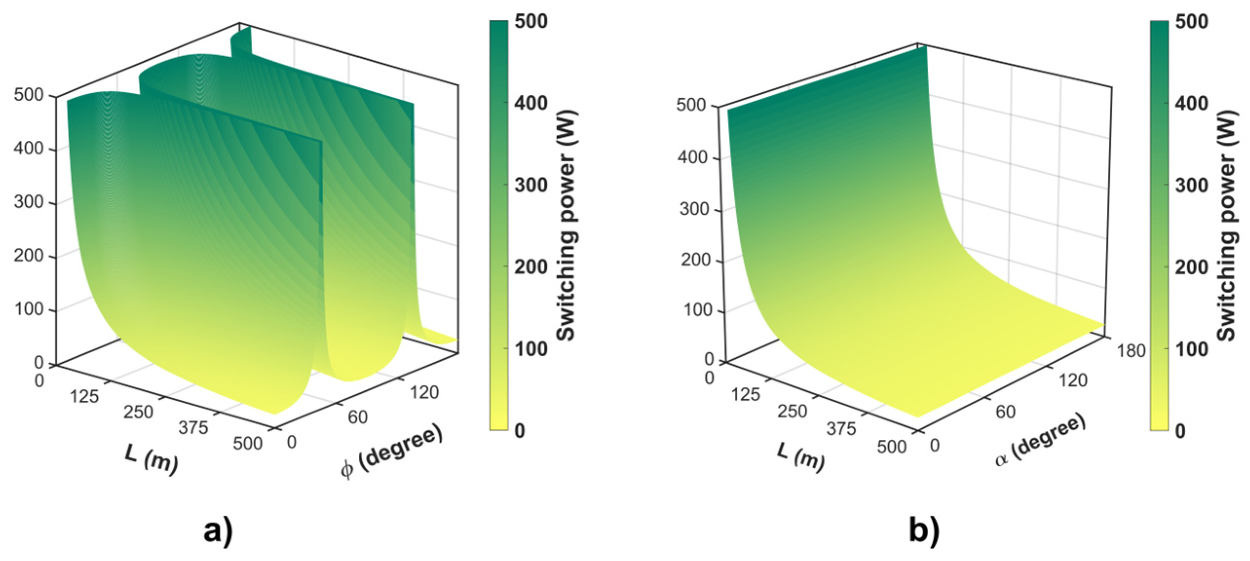
Figure 4a,b show the variation in Pπ when the polarization at the NOLM input is linear and circular, respectively; the variation is shown for L values of 0–500 m and for a half-wave retarder (HWR) with an input polarization angle (ϕ) (Figure 4a) and over a QWR (α) range of 0°–180° (Figure 4b). In Figure 4a, the maximum (infinite) Pπ value was obtained at ϕ = 45° and 135°, when aligned with the axis of the QWR plate (α). Figure 4b shows that the switchover power does not depend solely on α because, with circular input polarization, two beams always exist at any position of the QWR angle (α): circular CW and linear CCW beams. In other words, there is a maximum difference in ellipticity and Ac = 1 and 0. However, this does not imply that the maximum transmission always appears at the same power, as α also modifies the offset of the transmission curve. Thus, linear input polarization imparts great flexibility in controlling operating parameters, such as T, Pπ, and DR, by adjusting the QWR and input polarization angles. This enables adequate SA control for developing passively mode-locked fiber lasers. Here, increasing the fiber loop length decreases Pπ (red areas in Figure 4). Moreover, it yields larger NOLM operation variable spaces corresponding to T = 1 (dark areas in Figure 2 and Figure 3).
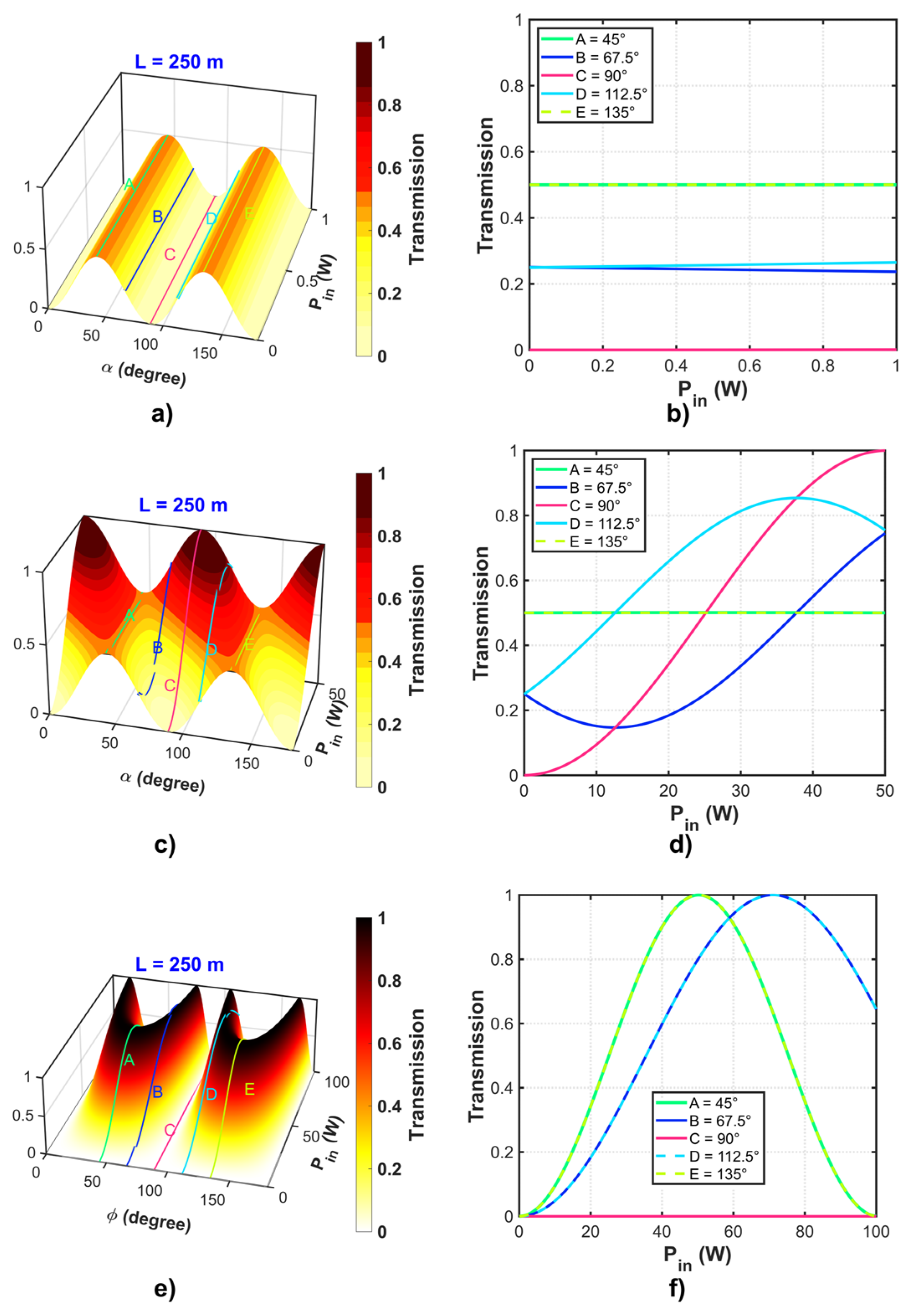
In Figure 5, 3D surface plots illustrate the NOLM operation in an F8L for circular and linear input polarizations. Five specific cases of QWR rotation (α) (A–E) over a range of Pin values and with a loop length of 250 m are considered in detail. Figure 5a,b show the periodic transmission with minimum and maximum values of 0 and 0.5, respectively, depending on the rotation of the QWR (α), for circular polarization at the NOLM input. In contrast, increasing power clearly has only a minor effect on the transmission, and it remains approximately constant as the power is increased (Figure 5b). The ability to easily adjust the QWR angle to realize low-power transmission (0–0.5) renders this type of NOLM useful for certain applications, such as optical regenerative systems [46].
Figure 5c,d show the results of the NOLM analysis in the nonlinear region with circular polarization at the input. For the transmission at lines A and E in Figure 5c, a constant transmission equal to 0.5 is observed (Figure 5d), indicating that for these angles of the QWR, the nonlinearity does not influence the transmission of the NOLM, and the transmission remains constant. At line B, the transmission initially tended to decrease as the power increased and then increased at higher power values. However, owing to the decreasing transmission, this angular dependence only enhanced the steady-state operation in an F8L. At line C, the NOLM transmission started from 0, indicating that the NOLM reflected the low-intensity components and did not allow the mode-locking operation to start. Thus, the power (Pin) must be increased to change the transmission value. Finally, at line D, different low-power behavior was observed; the transmission was nonzero, and this should allow a low-level initial noise signal to be amplified to initiate mode-locking.
Figure 5e,f show the NOLM analysis results in the nonlinear region, with a linear polarization at the input and α = 0°; in this case, five specific cases of different input linear polarizations (ϕ) are examined (lines A–E). For line A, the low-power transmission was independent of the input polarization state; in other words, adjusting ϕ did not change the value of the low-power transmission. Similarly, as in the previous case (Figure 5c,d), for lines B–E, Pin must be increased to obtain a different transmission value to facilitate the amplification of a small initial noise signal. In addition, the input angle (ϕ) can be adjusted to realize the required Pπ in the NOLM, and therefore, proper control over one of the most important parameters in the operation of the F8L can be achieved to trigger mode-locking and allow the NOLM to function as an SA.
Continuous-wave light is suitable for optical communication and mode-locked laser applications because an NOLM structure with a loop with a highly twisted single-mode optical fiber and a QWR breaks the polarization asymmetry. The pulse operation regime is determined by properly adjusting the NOLM low-power transmission by simply rotating the QWR angle. Such lasers offer advantages such as stability, efficiency, and better output beam quality compared with those of conventional lasers. They can be used as pump sources in optical systems and in communication systems.
The optimal parameters required are the input polarization, input power, and loop length. In pulsed laser applications, the NOLM can be used as an SA to achieve ultrafast optical pulses, especially a noise-like pulse. This is essential in the design process of an F8L through the mode-locking technique. An advantage of this analysis with 3D surface plots is a complete and detailed view of the NOLM transmission to determine the optimal transmission characteristics for high- and low-power operation. For example, in the design of a pulsed laser by the mode-locking technique using an NOLM as an SA, we can determine the tuning parameters by using PC plates that can be placed at the input of the NOLM (HWR) and the plate in the loop of the NOLM (QWR). With the visual information, we can determine the optimal positions for the operation of the fiber laser as a continuous-wave laser (continuous transmission) and pulsed laser (transmission with initial noise). In addition, by analyzing the switchover power and DR, we can determine the minimum power required in the NOLM to function as a modulator to allow it to function as an optical switch and ensure flexibility for power management in the fiber optic device.
The high power considered in the numerical part allowed us to observe how it influences the transmission change and the operating parameters in the NOLM. This increase in the initial transmission (also referred to as initial noise) in the device can be amplified as the light propagates through the NOLM and results in a self-starting characteristic in the pulsed laser. As the initial noise is amplified, a precession of modes is initiated, wherein the fluctuations, or amplification noise, are converted into well-defined and stable optical pulses. This eventually results in the generation of laser pulses. Consequently, the analysis of this type of polarization in the loop in the NOLM is highly resistant to polarization-induced disturbances and reduced to phase shift owing to the Kerr effect. This makes NOLMs suitable for applications involving the transmission of optical solitons.

4. Conclusions

In this study, a numerical analysis was conducted based on the Jones matrix formalism of NOLM transmissions for linear and circular input polarizations using 3D graphs. The simulation results demonstrated the simultaneous dependence of the transmission on multiple pairs of variables, including the fiber loop length, input power, QWR angle, and input polarization. These results demonstrate the feasibility of achieving greater control over the switching power of NOLM devices and provide more detailed and accessible visualizations to determine the operating conditions for the experimental F8L development. Moreover, greater flexibility in the experimental control of operational parameters such as transmission, switching power, and DR was achieved by adjusting the QWR angle for circular input polarization or by tuning the HWR for linear input polarization. Our method represents a more detailed and accessible approach to identify appropriate NOLM operating conditions. By using the proposed NOLM design as an SA, a laser with mode-locking functionality was realized by adjusting only the QWR plate and input polarizer. However, in this study, only linear and circular light polarization at the NOLM input were analyzed. Elliptical polarization generation and control require complex optical components, thereby increasing the complexity of the system design and alignment. This can lead to unwanted interactions with other optical components in the system and negatively affect signal quality and overall device performance. Moreover, in practical applications, several drawbacks and constraints delineated in the investigation, such as the potential physical degradation of optical fibers and thermal energy generation within the components, represent pivotal considerations when engaging with elevated power levels in fiber optics. These variables influence the stability, efficacy, and operational longevity of individual components and overarching systems.

Author Contributions

Conceptualization, J.D.F.-R. and J.C.H.-G.; methodology, J.D.F.-R., J.C.H.-G. and J.M.E.-A.; investigation, O.P., J.P.L.-C. and R.R.-L.; writing—original draft preparation, V.P.S.-A., J.P.L.-C. and J.C.E.-L.; writing—review and editing, J.D.F.-R., J.C.H.-G. and J.M.E.-A.; visualization, J.H.B.-Z. and J.R.M.-A.; All authors have read and agreed to the published version of the manuscript.

Funding

We are grateful for the Autonomous University of Tamaulipas (Mexico) for the financial support for the publication of the article.

Institutional Review Board Statement

Not applicable.

Informed Consent Statement

Not applicable.

Data Availability Statement

Under suitable request.

Acknowledgments

Jose D. Filoteo-Razo is grateful to CONAHCYT for the postdoctoral fellowship (CVU: 518100) with project “Estancias Posdoctorales por México 2022” No. 2840970. This work was supported by CONAHCYT through the project Ciencia de Frontera CF-2023-G-109. We are grateful for the Autonomous University of Tamaulipas (Mexico) for the financial support for the publication of the article.

Conflicts of Interest

The authors declare no conflict of interest.

References

  1. Hänsel, W.; Hoogland, H.; Giunta, M.; Schmid, S.; Steinmetz, T.; Doubek, R.; Mayer, P.; Dobner, S.; Cleff, C.; Fischer, M.; et al. All Polarization-Maintaining Fiber Laser Architecture for Robust Femtosecond Pulse Generation. In Exploring the World with the Laser: Dedicated to Theodor Hänsch on His 75th Birthday; Springer: Berlin/Heidelberg, Germany, 2018; pp. 331–340. ISBN 9783319643465. [Google Scholar]
  2. Wang, M.; Liu, M.; Chen, Y.; Ouyang, D.; Zhao, J.; Pei, J.; Ruan, S. Stable Noise-like Pulse Generation in All-PM Mode-Locked Tm-Doped Fiber Laser Based on NOLM. Chin. Opt. Lett. 2021, 19, 91402. [Google Scholar] [CrossRef]
  3. Han, Y.; Guo, Y.; Gao, B.; Ma, C.; Zhang, R.; Zhang, H. Generation, Optimization, and Application of Ultrashort Femtosecond Pulse in Mode-Locked Fiber Lasers. Prog. Quantum Electron. 2020, 71, 100264. [Google Scholar] [CrossRef]
  4. Yamamoto, T.; Yoshida, E.; Nakazawa, M. Ultrafast Nonlinear Optical Loop Mirror for Demultiplexing 640 Gbit/s TDM Signals. Electron. Lett. 1998, 34, 1013–1014. [Google Scholar] [CrossRef]
  5. Zhang, X.; Cao, T.; Dong, W. Engineering Nonlinear Effects of Quantum-Well Semiconductor Optical Amplifiers for Applications in Optical Signal Processing. IEEE J. Sel. Top. Quantum Electron. 2022, 29, 1–11. [Google Scholar] [CrossRef]
  6. Yang, Y.; Wen, F.; Zhao, T.; Yang, F.; Wu, B.; Qiu, K. Optical Reservoir-Based Noise Compensation in a Space Division Multiplexing Transmission System. In Proceedings of the Asia Communications and Photonics Conference, Shanghai, China, 24–27 October 2021; Optica Publishing Group: Washington, DC, USA, 2021; p. T4A-258. [Google Scholar]
  7. Prince, M.N.H.; Faisal, M.; Majumder, S.P. Performance Analysis of an Optical TDM Transmission Link Considering Fiber Dispersion and Demultiplexer Crosstalk. Optik (Stuttg.) 2022, 251, 168435. [Google Scholar] [CrossRef]
  8. Guo, B.; Wen, F.; Wu, B.; Qiu, K. Polarization Rotation Enhanced Nonlinear-Optical Loop Mirror (PR-NOLM) Multilevel Amplitude Regenerator. In Proceedings of the Optical Fiber Communication Conference, San Francisco, CA, USA, 6–10 June 2021; Optica Publishing Group: Washington, DC, USA, 2021; p. W6A-9. [Google Scholar]
  9. Ghazali, N.F.; Wahid, M.H.A.; Hambali, N.A.M.; Juhari, N.; Zahari, S.M.; Shahimin, M.M. Characterization of All-Optical Tofolli and Peres Gates Employing Optimized SOA-NOLM. In Proceedings of the AIP Conference Proceedings, Putrajaya, Malaysia, 22 August 2019; AIP Publishing: Melville, NY, USA, 2020; Volume 2203. [Google Scholar]
  10. Anagha, E.G.; Jeyachitra, R.K. Review on All-Optical Logic Gates: Design Techniques and Classifications–Heading toward High-Speed Optical Integrated Circuits. Opt. Eng. 2022, 61, 60902. [Google Scholar] [CrossRef]
  11. Semaan, G.; Braham, F.B.; Fourmont, J.; Salhi, M.; Bahloul, F.; Sanchez, F. 10 ΜJ Dissipative Soliton Resonance Square Pulse in a Dual Amplifier Figure-of-Eight Double-Clad Er:Yb Mode-Locked Fiber Laser. Opt. Lett. 2016, 41, 4767–4770. [Google Scholar] [CrossRef] [PubMed]
  12. Torres-Muñoz, O.S.; Pottiez, O.; Bracamontes-Rodriguez, Y.; Lauterio-Cruz, J.P.; Ibarra-Villalon, H.E.; Hernandez-Garcia, J.C.; Bello-Jimenez, M.; Kuzin, E.A. Simultaneous Temporal and Spectral Analysis of Noise-like Pulses in a Mode-Locked Figure-Eight Fiber Laser. Opt. Express 2019, 27, 17521–17538. [Google Scholar] [CrossRef]
  13. Hernández-Escobar, E.; Bello-Jiménez, M.; Pottiez, O.; Ibarra-Escamilla, B.; López-Estopier, R.; Duran-Sánchez, M.; García Ramírez, M.A.; Kuzin, E.A. Elimination of Continuous-Wave Component in a Figure-Eight Fiber Laser Based on a Polarization Asymmetrical NOLM. Laser Phys. 2017, 27, 075105. [Google Scholar] [CrossRef]
  14. Guo, Y.-X.; Li, X.-H.; Guo, P.; Zheng, H. Supercontinuum Generation in an Er-Doped Figure-Eight Passively Mode-Locked Fiber Laser. Opt. Express 2018, 26, 9893. [Google Scholar] [CrossRef]
  15. Braham, F.B.; Semaan, G.; Bahloul, F.; Salhi, M.; Sanchez, F. Experimental Optimization of Dissipative Soliton Resonance Square Pulses in All Anomalous Passively Mode-Locked Fiber Laser. J. Opt. 2017, 19, 105501. [Google Scholar] [CrossRef]
  16. Addanki, S.; Amiri, I.S.; Yupapin, P. Review of Optical Fibers-Introduction and Applications in Fiber Lasers. Results Phys. 2018, 10, 743–750. [Google Scholar] [CrossRef]
  17. Zazali, N.A.; Latif, A.A.; Lau, K.Y.; Mahdi, M.A.; Muhammad, F.D.; Yusoff, Z.; Abdul-Rashid, H.A.; Radzi, N.M.; Tamchek, N.; Abu Bakar, M.H. 860 Femtoseconds Mode-Locked Fiber Laser by Gallium Co-Doped Erbium Fiber (Ga-EDF). Results Phys. 2019, 15, 102644. [Google Scholar] [CrossRef]
  18. Zhang, T.; Pan, Y.; Yang, L.; Tian, Z.; Liu, W.; Miao, J.; Dong, Q. NOLM-Based Mode-Locked Yb-Doped Fiber Laser with Wide-Spectrum. J. Electron. Res. Appl. 2019, 3, 35–44. [Google Scholar] [CrossRef]
  19. Birks, T.A.; Morkel, P. Jones Calculus Analysis of Single-Mode Fiber Sagnac Reflector. Appl. Opt. 1988, 27, 3107. [Google Scholar] [CrossRef]
  20. Stępień, W.; Szczepanek, J.; Kardaś, T.; Nejbauer, M.; Radzewicz, C.; Stepanenko, Y. Study on Parameters of Fiber Loop Mirrors as Artificial Saturable Absorbers. In Proceedings of the Frontiers in Ultrafast Optics: Biomedical, Scientific, and Industrial Applications XVII, San Francisco, CA, USA, 29 January–2 February 2017. [Google Scholar]
  21. Ibarra-Escamilla, B.; Kuzin, E.A.; Álvarez-Tamayo, R.I.; Duran-Sanchez, M.; Pottiez, O.; Haus, J.W. Symmetric Nonlinear Optical Loop Using the Nonlinear Polarization Rotation. In Proceedings of the 2015 IEEE Summer Topicals Meeting Series (SUM), Nassau, Bahamas, 13–15 July 2015; pp. 205–206. [Google Scholar]
  22. Pottiez, O.; Kuzin, E.A.; Ibarra-Escamilla, B.; Méndez-Martínez, F. Theoretical Investigation of the NOLM with Highly Twisted Fibre and a λ/4 Birefringence Bias. Opt. Commun. 2005, 254, 152–167. [Google Scholar] [CrossRef]
  23. Pottiez, O.; Kuzin, E.A.; Ibarra-Escamilla, B.; Camas-Anzueto, J.T.; Gutierrez-Zainos, F. Easily Tunable Nonlinear Optical Loop Mirror Based on Polarization Asymmetry. Opt. Express 2004, 12, 3878–3887. [Google Scholar] [CrossRef]
  24. Hernandez-Garcia, J.C.; Estudillo-Ayala, J.M.; Pottiez, O.; Filoteo-Razo, J.D.; Lauterio-Cruz, J.P.; Sierra-Hernandez, J.M.; Rojas-Laguna, R. Flat Supercontinuum Generation by a F8L in High-Energy Harmonic Noise-like Pulsing Regime. Laser Phys. Lett. 2016, 13, 125104. [Google Scholar] [CrossRef]
  25. Lauterio-Cruz, J.P.; Hernandez-Garcia, J.C.; Pottiez, O.; Estudillo-Ayala, J.M.; Kuzin, E.A.; Rojas-Laguna, R.; Santiago-Hernandez, H.; Jauregui-Vazquez, D. High Energy Noise-like Pulsing in a Double-Clad Er/Yb Figure-of-Eight Fiber Laser. Opt. Express 2016, 24, 13778. [Google Scholar] [CrossRef] [PubMed]
  26. Pottiez, O.; Kuzin, E.A.; Ibarra-Escamilla, B.; Camas-Anzueto, J.T.; Gutiérrez-Zainos, F. Experimental Demonstration of NOLM Switching Based on Nonlinear Polarisation Rotation. Electron. Lett. 2004, 40, 1. [Google Scholar] [CrossRef]
  27. Doran, N.J.; Wood, D. Nonlinear-Optical Loop Mirror. Opt. Lett. 1988, 13, 56–58. [Google Scholar] [CrossRef]
  28. Feng, Z.; Rong, Q.; Qiao, X.; Shao, Z.; Su, D. Experimental Observation of Different Soliton Types in a Net-Normal Group-Dispersion Fiber Laser. Appl. Opt. 2014, 53, 6237–6242. [Google Scholar] [CrossRef] [PubMed]
  29. Bernabe, V.; Kuzin, E.A.; Ibarra-Escamilla, B.; Korneev, N.; Flores-Rosas, A. Efectos de Dispersión a Primer Orden y SRS Sobre Un Pulso Con Polarización Circular Dentro de Un NOLM Con Fibra Torcida En Lazo. Rev. Mex. Física 2013, 59, 419–425. [Google Scholar]
  30. Kuzin, E.A.; Korneev, N.; Haus, J.W.; Ibarra-Escamilla, B. Theory of Nonlinear Loop Mirrors with Twisted Low-Birefringence Fiber. J. Opt. Soc. Am. B 2001, 18, 919–925. [Google Scholar] [CrossRef]
  31. Pang, Y.; Ma, S.; Ji, Q.; Zhao, X.; Li, Y.; Qin, Z.; Liu, Z.; Xu, Y. Frequency Comb Generation Based on Brillouin Random Lasing Oscillation and Four-Wave Mixing Assisted with Nonlinear Optical Loop Mirror. In Proceedings of the Photonics; MDPI: Basel, Switzerland, 2023; Volume 10, p. 296. [Google Scholar]
  32. Guo, B.; Wen, F.; Wu, B.; Sun, F.; Qiu, K. All-Optical Multilevel Amplitude Regeneration Based on Polarization-Orthogonal Continuous-Wave-Light-Assisted Nonlinear-Optical Loop Mirror (PC-NOLM) Subsystem. IEEE Access 2019, 7, 149666–149671. [Google Scholar] [CrossRef]
  33. Guo, B.; Wu, B.; Wen, F.; Qiu, K. All-Optical OPC-NOLM Amplitude Regeneration for Intact Phase Preservation. Acta Opt. Sin. 2023, 43, 0306001. [Google Scholar]
  34. Kikuchi, K.; Tanemura, T. Circular-Birefringence Fiber for Nonlinear Optical Signal Processing. J. Light. Technol. 2006, 24, 4108–4119. [Google Scholar]
  35. Flores-Rosas, A.; Peralta-Hernandez, J.I.; Bracamontes-Rodríguez, Y.E.; Villagomez-Bernabe, B.A.; Beltrán-Pérez, G.; Pottiez, O.; Ibarra-Escamilla, B.; Rojas-Laguna, R.; Kuzin, E.A. Observation of a High Grade of Polarization of Solitons Generated in the Process of Pulse Breakup in a Twisted Fiber. JOSA B 2014, 31, 821–826. [Google Scholar] [CrossRef]
  36. Guo, L.; Gan, Z.; Liang, X. 27nJ, 114fs Pulses from an Environmentally Stable All-Normal All-PM Yb-Doped Fiber Laser Mode-Locked with a Nonlinear Amplifying Loop Mirror. IEEE Photonics J. 2022, 14, 1–6. [Google Scholar] [CrossRef]
  37. Kobtsev, S.M. Artificial Saturable Absorbers for Ultrafast Fibre Lasers. Opt. Fiber Technol. 2022, 68, 102764. [Google Scholar] [CrossRef]
  38. Bello-Jiménez, M.; Kuzin, E.A.; Pottiez, O.; Ibarra-Escamilla, B.; Flores-Rosas, A.; Durán-Sánchez, M. Soliton Extraction from a Bunch of Solitons Resulting from Pulse Breakup by Using a Nonlinear Optical Loop Mirror. JOSA B 2009, 26, 1456–1462. [Google Scholar] [CrossRef]
  39. Pottiez, O.; Escamilla, B.I.; Kuzin, E.A.; Haus, J.W. Nonlinear Switching in a Symmetrical Sagnac Interferometer Including a Quarter-Wave Plate. In Proceedings of the OSA Trends in Optics and Photonics Series; Optica Publishing Group; Bellingham, WA, USA, 2004. [Google Scholar]
  40. Pottiez, O.; Ibarra-Escamilla, B.; Kuzin, E.A. High-Quality Amplitude Jitter Reduction and Extinction Enhancement Using a Power-Symmetric NOLM and a Polarizer. Opt. Express 2007, 15, 2564–2572. [Google Scholar] [CrossRef] [PubMed]
  41. Yang, Y.; Wen, F.; Yang, F.; Qiu, K. Optical Dispersion Compensation through a Nonlinear-Optical Loop Mirror (NOLM)-Based Optical Reservoir. In Proceedings of the 2022 Photonics & Electromagnetics Research Symposium (PIERS), Hangzhou, China, 25–27 April 2022; IEEE: Piscataway, NJ, USA, 2022; pp. 557–562. [Google Scholar]
  42. Saeedizadeh, R.; Sabouri, S.G.; Khorsandi, A. Engineering the Temporal Shape of a Chirped Pulse Compressed in a Pressure-Gradient-Based Cascaded Hollow-Core Photonic Crystal Fiber. Opt. Quantum Electron. 2023, 55, 515. [Google Scholar] [CrossRef]
  43. Pan, H.; Chen, Z.; Zhang, A.; Zhang, B.; Peng, Y.; Liu, Z.; Wang, Q.; Cui, N.; Zhou, J. Tunable and Switchable Low-Threshold Multi-Wavelength Erbium-Doped Fiber Pulsed Laser Based on Lyot Filter and NOLM. J. Russ. Laser Res. 2023, 44, 303–313. [Google Scholar] [CrossRef]
  44. Kaur, R.; Kaur, B.; Kaur, H. A Review on OTDM Transmission. Int. J. Eng. Res. Technol. 2023, 12. [Google Scholar]
  45. Tapia-Garcia, M.R.; Hernandez-Garcia, S.G.; Hernandez-García, J.C.; Razo-Medina, D.A.; Estudillo-Ayala, J.M.; Pottiez, O.; Filoteo-Razo, J.D.; Lauterio-Cruz, J.P.; Gomez-Rodriguez, F.A.; Rojas-Laguna, R. Experimental Study of a F8L Using an Automated Adjustment System Based in Polarization Control Plates. In Fiber Lasers XX: Technology and Systems; SPIE: Bellingham, WA, USA, 2023; Volume 12400, pp. 174–180. [Google Scholar]
  46. Avazpour, M.; Beltrán Pérez, G.; Kuzin, E. Suppression of Kelly Sidebands and Compression of Soliton Spectrum Using a Polarization Imbalance Nonlinear Loop Mirror. In Progress in Optomechatronic Technologies: Proceedings of International Symposium on Optomechatronic (2018); Springer: Berlin, Germany, 2019; pp. 147–152. [Google Scholar]
Figure 1. Configuration of the NOLM investigated in this study.
Photonics 10 01071 g001
Figure 2. Three-dimensional surface plots of NOLM transmission for circular input polarization as a function of QWR angle (α) and input power (Pin) for (a) loop length L = 100 m, (d) L = 300 m, and (g) L = 500 m. (b,e,h) Contour maps showing the same data as in (a,d,g), respectively. (c,f,i) Switching power (Pπ) as a function of the fiber loop length (L) corresponding to the data shown in (a,b), (d,e), and (g,h), respectively.
Photonics 10 01071 g002
Figure 3. Three-dimensional surface plots of NOLM transmission with linear input polarization as a function of input polarization angle (ϕ) and input power (Pin) for (a) loop length L = 100 m, (d) L = 300 m, and (g) L = 500 m. (b,e,h) Contour maps corresponding to the data shown in (a,d,g), respectively. (c,f,i) Switching power as a function of ϕ corresponding to the data shown in (a,b), (d,e), and (g,h), respectively.
Photonics 10 01071 g003
Figure 4. Three-dimensional surface plots showing switching power (Pπ) for NOLM transmission versus loop length (L) and (a) polarization angle (ϕ) (for linear input polarization) or (b) QWR angle (α) (for circular input polarization).
Photonics 10 01071 g004
Figure 5. NOLM operation in an F8L with a loop length of 250 m. Three-dimensional surfaces for (a) circular input polarization with low power, (c) circular input polarization with high power, and (e) linear input polarization with high power. Five specific cases of QWR rotation (α) (A–E) over a range of Pin values: (b,d) 2D analysis of NOLM transmission vs. Pin at high and low power, respectively. (f) Input polarization in 2D analysis of NOLM transmission vs. Pin at high power.
Photonics 10 01071 g005
Table 1. Jones matrices of optical elements for circular input polarization.
Optical Element DescriptionNomenclatureJones Matrix
Quarter-wave plate with clockwise direction Q W R C W 1 2 1 i e 2 i α i e 2 i α 1
Quarter-wave plate with counterclockwise direction Q W R C C W 1 2 1 i e 2 i α i e 2 i α 1
Twisted optical fiber with clockwise direction F C W e i β L P i n 2 0 0 e i β L P i n
Twisted optical fiber with counterclockwise direction F C C W e 3 i β L P i n 4 0 0 e 3 i β L P i n 4
Table 2. Jones matrices of optical elements for a linear input polarization.
Optical Element
Description
NomenclatureJones Matrix
Quarter-wave plate with clockwise direction Q W R C W 1 2 1 i e 2 i α i e 2 i α 1
Quarter-wave plate with counterclockwise direction Q W R C C W 1 2 1 i e 2 i α i e 2 i α 1
Twisted optical fiber with clockwise direction F C W e 3 i β L P i n 4 0 0 e 3 i β L P i n 4
Twisted optical fiber with counterclockwise direction F C C W e i β 3 + s i n 2 ϕ L P i n 4 0 0 e i β 3 s i n 2 ϕ L P i n 4
Disclaimer/Publisher’s Note: The statements, opinions and data contained in all publications are solely those of the individual author(s) and contributor(s) and not of MDPI and/or the editor(s). MDPI and/or the editor(s) disclaim responsibility for any injury to people or property resulting from any ideas, methods, instructions or products referred to in the content.