Review

High-Quality Laser-Accelerated Ion Beams from Structured Targets

1
Extreme Light Infrastructure ERIC, ELI Beamlines Facility, Za Radnici 835, 252 41 Dolni Brezany, Czech Republic
2
Faculty of Nuclear Sciences and Physical Engineering, Czech Technical University in Prague, Brehova 7, 11519 Prague, Czech Republic
3
Institute of Laser Engineering, Osaka University, Suita 565-0871, Osaka, Japan
4
Kansai Photon Science Institute, National Institutes for Quantum Science and Technology, 8-1-7 Umemidai, Kizugawa-shi 619-0215, Kyoto, Japan
*
Author to whom correspondence should be addressed.
Photonics 2023, 10(1), 61; https://doi.org/10.3390/photonics10010061
Submission received: 2 June 2022 / Revised: 7 December 2022 / Accepted: 28 December 2022 / Published: 6 January 2023
(This article belongs to the Special Issue Progress in Laser Accelerator and Future Prospects)

Abstract

:
In this work, we reviewed our results on the prospect of increasing the quality of ion acceleration driven by high-intensity laser pulses using low-Z structured targets. It is shown that the radiation pressure acceleration mechanism dominates over target normal sheath acceleration for assumed laser target parameters when the laser intensity is high enough. The target thickness is optimized for this regime and double-layer structure is investigated. When a corrugation is fabricated on the interface of such a target, a relativistic instability with Rayleigh–Taylor and Richtmyer–Meshkov like features can be driven by the target interaction with a high intensity laser pulse. The proper development of this instability leads to the generation of a collimated quasi-monoenergetic ion beam with lower emittance, divergence, and energy spread compared to a single and double-layer target with planar interface. A steep-front laser pulse is used in our simulations to mitigate other type of instabilities arising at the target surface from the laser–target interaction. We discuss the use of a plasma shutter to generate the required pulse profile, which also locally increases intensity. The obtained shape improves the ion acceleration, including higher maximal energy and lower beam divergence, in our simulation of a high-Z target.

1. Introduction

Laser driven ion acceleration is currently receiving particular scientific attention for its impressive applications, such as hadron therapy [1,2,3], nuclear fusion [4,5], use in material sciences and nuclear physics research [6], and other areas [7,8,9]. Cryogenic (solid) hydrogen targets provide an interesting medium for ion acceleration as they can be made relatively thin, with low density, lacking contaminants, debris-free, and can be used in high-repetition laser–target experiments [10,11,12,13].
In this work, we review our results on the prospect of increasing the quality of future ion acceleration driven by the current and forthcoming multi-(tens) PW laser systems (such as ELI Beamlines [14,15,16], APOLLON [17], ELI NP [18], and SEL [19]) using structured cryogenic targets. It is shown that, with the use of a 10 PW-class laser system with pulse duration over 100 fs and cryogenic targets of current thickness [11], the radiation pressure acceleration (RPA) [20] mechanism dominates over the target normal sheath acceleration (TNSA) [21,22] in both the number of accelerated protons (with energy > 10 MeV) and the maximal reached energies [23]. The laser–target conditions relevant for RPA has been thoroughly investigated in this millennia, e.g., in Refs. [24,25,26], and the experimental indications of the RPA regime have already been observed [27,28,29,30]. Note that the laser–target condition optimal for RPA overlaps with other mechanisms investigated at moderately relativistic intensities [31], such as phase stable acceleration (PSA) [32,33], which is also referred to as coherent acceleration of ions by laser (CAIL) [34]. Usually, two subregimes of RPA are distinguished, the hole boring [35,36,37] for a relatively thick target and light sail [38,39] for ultrathin targets; the transitions between them can occur by decreasing the target areal density and/or increasing the laser pulse intensity [40]. Therefore, the thickness of the cryogenic target for the use of a 100 PW class laser system was reduced in our simulations [41] to be optimized for the RPA mechanism [20]. The properties of the generated particles can be improved using structured targets made of heavy and light ion layers [1,42,43,44] and by properly introducing instability, transforming the target into compact ion bunches either from the planar target [45] or the target with a modulated surface [46]. We investigate the introduction of the initial corrugation on the interface between the double-layer target [41] with a high intensity laser pulse. In these conditions a relativistic instability arises, which is determined by the target geometry, having features of the Rayleigh–Taylor (RTI) [47,48] and Richtmyer–Meshkov (RMI) [49,50] instabilities. Both of them are currently being thoroughly investigated [51,52,53,54,55,56,57,58,59]. They can be found on different space scales ranging from the parsec-size in astrophysics (e.g., the development of the filament structure of the Crab Nebula [60]) to a μ m-size in laser-plasma, e.g., affecting the creation of the hot spot in the inertial fusion [61]. The main differences between RTI and RMI are shown via the experimental results [62,63] in Figure 1. The driving force is in principle continuous for RTI, resulting in exponential growth, therefore experiencing slower growth in early time in Figure 1 (left). RTI can occur only when the acceleration is being driven from lighter to heavier media [51]. In contrast, the RMI behavior is rather impulsive and a perturbation grows linearly in time, as shown in Figure 1 (right), and it can occur for shocks directed toward either side of the interface. In the case of heavy-light direction of acceleration, RMI exhibits a characteristic phase inversion of the corrugated interface, as was predicted in theory [53,64,65] and shown via experiment [63]. The inversion (switch of corrugation maxima and minima) is visible in Figure 1 (right), e.g., compare the position of maxima and minima in sub-figures (a) and (d). In contrast, the maxima and minima stay at the same position for RTI in Figure 1 (left).
The instability can be influenced by the fabricated interface corrugation to generate a high-density proton bunch, which can be accelerated by the radiation pressure as a compact structure. Therefore, the generated proton beam has good quality and properties such as low energy spread, divergence, and emittance [41].
In our simulations, we use a steep-front laser pulse to mitigate the development of other transverse instabilities (with relatively short wavelength) arising from laser–target interaction on the target surface, usually ascribed to Rayleigh–Taylor [45,66,67] or electron-ion coupled instability [68,69], as was proposed by theory [45] to increase the target stability. Without this treatment, the target can be shattered into many small bunches, ignoring the target geometry. We discuss the use of the plasma shutter (usually a thin solid foil attached to the front surface of the target with a gap between them) [70,71,72,73,74,75,76,77,78,79] to obtain the required pulse profile. In addition to the steep-rising front, the shutter can also locally increase the peak intensity of the laser pulse [78]. The obtained shape can improve the ion acceleration from the target located behind the plasma shutter, including higher maximal energy and lower divergence [79].
The paper is organized as follows. The simulation method and parameters of the simulations used in the particular subsections of results are described in Section 2. Section 3, which contains the results, is divided into three sections. First, the dominance of the RPA mechanism for the assumed parameters is shown in Section 3.1. The target thickness is then reduced, and the influence of the corrugated interface of the double-layer target, including the bunch generation with low emittance, divergence, and energy spread, is investigated and compared to similar targets in Section 3.2. Finally, the foil stability is discussed in Section 3.3, comparing the results using steep-front and full-front laser pulses. The use of the plasma shutter for our concept and for heavy ion acceleration from different targets is also discussed in this section. Appendix A contains the description of the virtual reality application (called VBL-Virtual BeamLine) used for visualization of our results.

2. Methods

We performed 2D and 3D particle-in-cell simulations using the code EPOCH [80]. In Section 3.1 and Section 3.2, the quantum electrodynamics (QED) module [81] resolving non-linear Compton scattering is included in the simulations, assuming high intensity interaction. The EPOCH default Yee solver was used, and current smoothing option was applied. In Section 3.1, the triangular shape of particles was used, whereas the preprocessor directive for 3rd order b-spline shape function of the quasi-particles (PARTICLE_SHAPE_BSPLINE3) was used in Section 3.2 and Section 3.3. The main laser–target simulation parameters are shown in Table 1, and further simulation details are described in the following paragraphs of this section.
In Section 3.1, the laser pulse parameters of the reference 2D case are as follows: p-polarization, peak intensity I = 3 × 10 22 W / cm 2 , wavelength λ = 1.1 μ m , beam width is 5 μ m , and full pulse duration is 320 fs for sin 2 ( t ) shape in intensity. Its energy corresponds to a Gaussian temporal profile with 150 fs FWHM. The peak power is about 9 PW and energy is 1.35 kJ. Dependence on intensity ranging between I = 0.375 × 10 22 W / cm 2 and I = 3 × 10 22 W / cm 2 is also discussed while keeping the other parameters same (i.e., changing pulse energy and power). The intensity of I = 1.5 × 10 22 W / cm 2 was used for 3D simulation. The target is made by 25 μ m thick fully ionized hydrogen target with electron density of 56 n c 1.1 , where n c 1.1 is the non-relativistic critical density for λ = 1.1 μ m . For the 3D simulations and virtual reality visualization, the laser and target parameters were reduced by a factor of 5/3 to 200 fs and 15 μ m. For 2D simulations, square cells with the size of 20 nm are used. Each cell occupied by plasma contains 56 electrons and 56 protons. For the 3D simulation, the cell size is 20 nm in the longitudinal direction and 30 nm in the transverse direction. The number of particles per cell was reduced to 10 electrons and 10 protons. More information about simulation parameters can be found in [23].
In Section 3.2 (and the first part of Section 3.3), the laser pulse parameters are as follows: s-polarization (electric field is perpendicular to the plane of incidence), peak intensity I = 1.37 × 10 23 W / cm 2 , wavelength λ = 1 μ m , beam width is 10 μ m , beam duration at FWHM is equal to 8 laser periods T. The steep front is realized by filtering out the low-intensity part at the front of the laser pulse until 2.4 T (i.e., 30% of FWHM) before the peak of the temporal Gaussian profile. The double-layer target consists of light (solid hydrogen) and heavy (deuterium) ion layers. The electron density is same in both layers n e = 48 n c , where n c is the non-relativistic critical density for λ = 1 μ m . The deuterium layer has the same electron and ion number density as the proton layer, but two times heavier ion mass. Square cells with the size of 10 nm are used. Each cell occupied by plasma contains 48 electrons and 48 protons/deuterium ions. More information about simulation parameters can be found in [41].
In the rest of Section 3.3 (results with the plasma shutter), the laser pulse parameters are as follows: p-polarization, peak intensity I = 1 × 10 22 W / cm 2 , wavelength λ = 1 μ m , beam width is 3 μ m , and full pulse duration is 64 fs for sin 2 ( t ) shape in intensity. Its energy corresponds to Gaussian temporal profile with 30 fs FWHM of 1 PW laser pulse. The plasma shutter is made of silicon nitride ( Si 3 N 4 ) solid foil. Full ionization of the foil is assumed with electron density n e = 835 n c , where n c is the non-relativistic critical density for λ = 1 μ m . The thickness of the plasma shutter is set to 20 nm. The target, located behind the plasma shutter, corresponds to a silver solid foil with thickness of 20 nm. Partial ionization of the target is assumed (charge number Z = 40 ), electron density is n e = 2100 n c . The mesh has square cells of the size 3 nm in 2D simulations and cuboid cells of the size 5 nm in the laser propagation direction and 25 nm in the transverse ones in 3D. The number of electrons in 2D is 835 particles per cell inside the plasma shutter (400 in 3D) and 1050 inside the target (1000 in 3D), respectively. The numbers of ions correspond to their charge ratios. More information about simulation parameters can be found in [78,79].

3. Results

3.1. The Prominence of Different Acceleration Mechanisms Using Cryogenic Targets

In order to properly optimize the target thickness and structure, one first needs to know which acceleration mechanism to focus on. More mechanisms usually occur during the laser–target interaction, and their interplay depends on the target and laser parameters [82]. Currently, the most employed acceleration mechanism is the target normal sheath acceleration (TNSA) [21,22]. In this section, we examine the shift from the TNSA dominated regime with the increasing laser pulse intensity for low density cryogenic targets of current thicknesses [11] and 10 PW class laser systems with pulse duration over 100 fs. Understanding of this topic then helps with choosing the parameters used for the structured cryogenic target in Section 3.2.
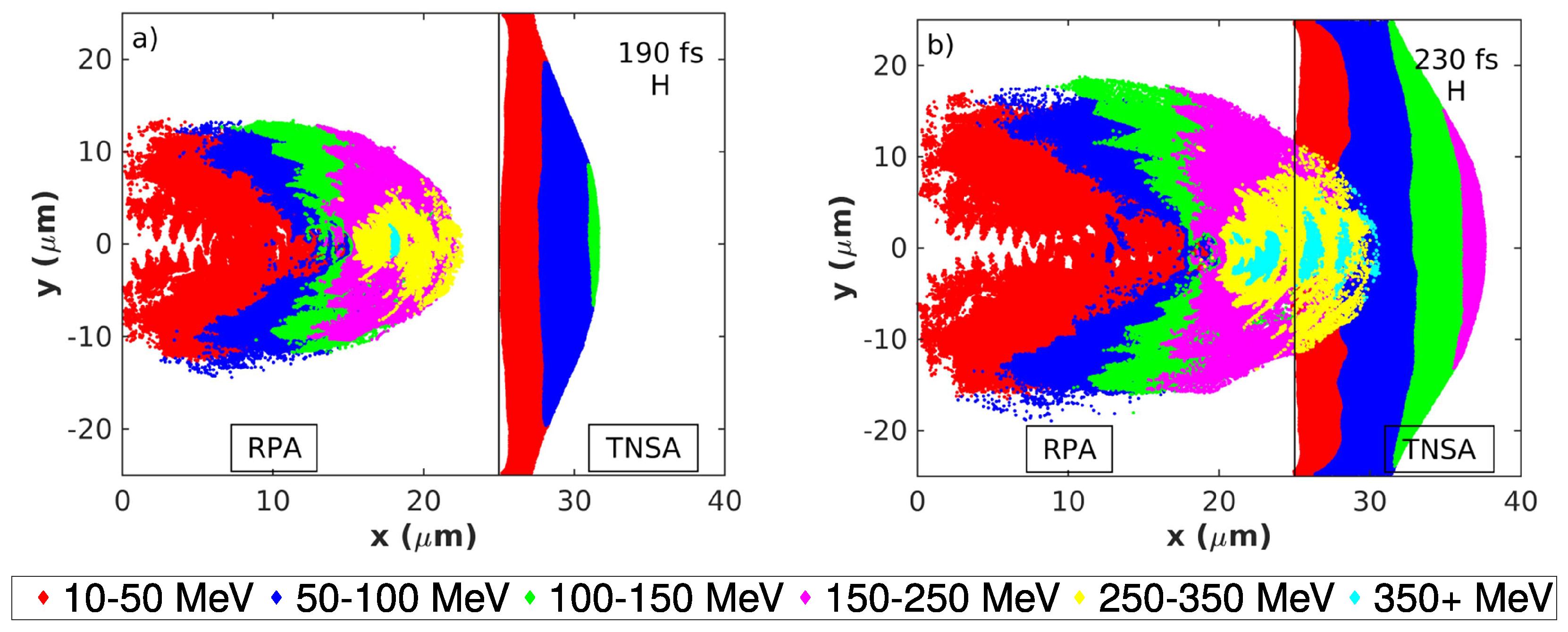
In our simulations [23], the assumed intensity ranges between I = 0.375 × 10 22 W / cm 2 and I = 3 × 10 22 W / cm 2 ; the thickness of the fully ionized hydrogen target is 25 μ m. We focuses on the difference of the well established TNSA mechanism and the emerging mechanisms that differ from it, mainly radiation pressure acceleration (RPA). These two mechanisms can be clearly distinguished from each other at the early and middle stages as they act at different positions of the target. The TNSA gets involved on the rear side of the target, whereas the RPA is acting on the front side and interior of the target. This behavior is shown in Figure 2 using the proton energy layers (i.e., protons at various energy intervals in the 2D simulation area) for the peak laser intensity I = 3 × 10 22 W / cm 2 . The conversion efficiency of the laser pulse energy to the high-energy protons (exceeding 10 MeV) in this case is about 27%.
The highest energies in the first stage (Figure 2a) are achieved by the RPA regime in the target interior. Here, the low density of the target provides good conditions for the hole boring phase of the RPA mechanism. The hole boring velocity inferred from our simulation is u h b = 0.31 c , which is slightly higher than the theoretical value of u h b = 0.26 c calculated using the analytical model [36]. The character c denotes speed of light in vacuum. In the second stage (Figure 2b), the target is still not transparent for the laser pulse, and the most energetic protons from the inside of the target (accelerated to velocities higher than u h b ) enter into the TNSA field behind the initial position of the target rear side (denoted by the black line). Although the ions from both populations are now located in the same area, they can still be distinguished from one another by the combination of their energy and position. The energy of protons accelerated by the TNSA mechanism strongly depends on their distance from the target rear side, with the most energetic protons located on top of the proton cloud, as can be seen in Figure 2a. Therefore, the entering RPA protons can be distinguished by their significantly higher energy, which does not fit the energy layer of the surrounding TNSA protons. Thus, RPA results in higher proton energy than TNSA also in this stage. The separation of the two populations is more visible in the pseudo-3D visualization, with the proton energy represented also by the vertical height (Figure 3). Here, the laser pulse (incoming from left) is represented in the gray scale, the electron density by the turquoise scale, and the scale for proton energy is ranging from white (zero energy) to purple (about 400 MeV) to light blue (over 600 MeV). Note that for this visualization, the laser and target parameters were reduced in the similar way as for the 3D simulations (factor of 5/3) discussed below, and only the protons reaching the highest energy at the end of the simulation (above 300 MeV) are being tracked (see more information in [83] and in Appendix A). The interactive visualization (available online [84]) is made in the virtual reality web-based application [85], discussed in Appendix A.
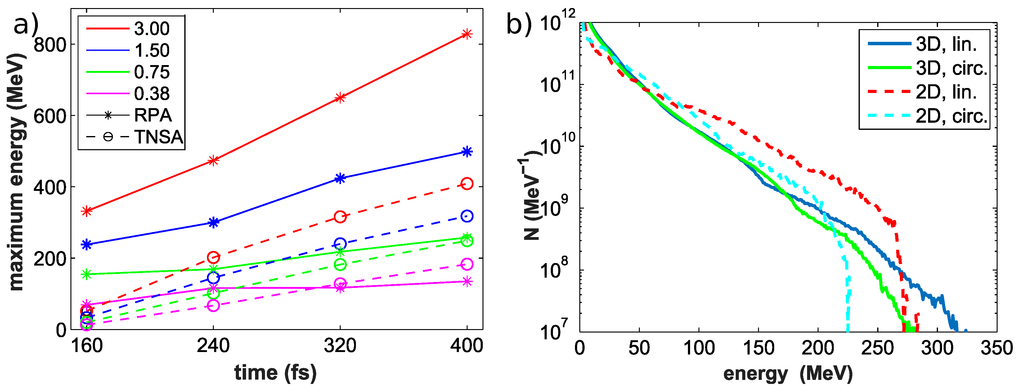
The third stage may occur if the laser pulses reach the rear side of the target and eventually punch through it, which happens around time t = 270 fs in the simulation with maximal intensity shown in Figure 2. The protons can be further accelerated to very high energies around the onset of the relativistic transparency by regimes such as the hybrid RPA-TNSA mechanism [86,87], break-out afterburner [88,89] and directed Coulomb explosion [90]. To see the dependence of the mechanisms interplay on intensity, other simulations were performed with the same parameters but with lower pulse intensities (and thus lower pulse power). Figure 4a shows the time evolution of the maximal reached proton energy by RPA (solid lines) and TNSA (dashed lines) in these simulations. Note that, for the times after the laser pulse burns through the target, all the ions originated from the target interior are labeled as RPA in Figure 4a for the sake of brevity.
The RPA mechanism accelerates protons to higher energies than the TNSA in our simulations with intensities above 0.75 × 10 22 W / cm 2 . Note that, for these simulations, the laser pulse reached the rear side of the target, as further discussed in reference [23]. For the lowest intensity case, the target is too thick for an efficient RPA acceleration, and the TNSA plays the role of the dominating mechanism in the sense of proton energy.
Two-dimensional simulations are known to usually overestimate the maximal reached energy and heating of electrons (especially in the linear p-polarization) [89,91]. Therefore, our findings are also verified via 3D simulations. Intensity I = 1.5 × 10 22 W / cm 2 is chosen for the demonstration. Both the laser pulse duration and target thickness are reduced by a factor of 5/3 to 200 fs and 15 μ m due to computational constraints. Corresponding 2D simulations with the same reductions and simulations with the circular polarization were also performed for comparison. The proton energy spectra at the time 260 fs are shown in Figure 4b. Unexpectedly, the 3D simulations resulted in higher maximal energy than their 2D counterparts for our parameters with a relatively thick target. Further examination by separation of TNSA and RPA protons shows that only the energy of ions accelerated by RPA is higher in the 3D simulations. For example, before mixing these two populations at time 180 fs, the maximal energy of RPA protons increases from 180 MeV to 255 MeV when the third dimension is included. In this stage, the RPA mechanism represents a clear hole boring phase. This increase can be explained with the effect of the self-focusing of the laser beam propagating in the plasma. The laser pulse intensity is thus higher in 3D, as the self-focusing is not limited into just one plane as it is in 2D (see the comparison of electron density and electric field in Figure 6 in [23]). Consequently, the hole boring velocity (and thus the proton energy) is higher in 3D.
In contrast, at the same time instant, the energy of protons accelerated by pure TNSA decreases from 155 MeV to 80 MeV, which corresponds to the previous observations related to higher electron heating in 2D [91].
Circular polarization is often proposed for the laser pulse interaction with ultra-thin targets as it can improve the foil stability and reduce the electron heating and consequently results in higher ion energy [28,66,67,92]. In our simulations, these advantages diminish as the larger thickness of the target prevents it from immediately breaking. The electron heating at later stages is also similar in the linear and circular polarization due to the bending of the target surface (see the discussion in [23]). Therefore, the proton energy spectra of 3D simulations are similar until the energy is approximately 185 MeV. The linear polarization enhances the tail of the proton spectrum, resulting in higher maximal energy than the circular one in our simulations. This behavior can be ascribed to the presence of the oscillatory component of the ponderomotive force.

3.2. Improving Ion Properties Using Double-Layer Targets with Interface Corrugation

On the basis of our findings in the previous section, we choose the cryogenic target optimized for the RPA mechanism in our next study involving future 100 PW class laser systems. The optimal thickness l [20] of such a target can be expressed as:
l λ = a 0 π n c n e ,
yielding the thickness of 2 μ m for our laser and target parameters (see Section 2). Here, a 0 is the dimensionless amplitude of the laser electric field.
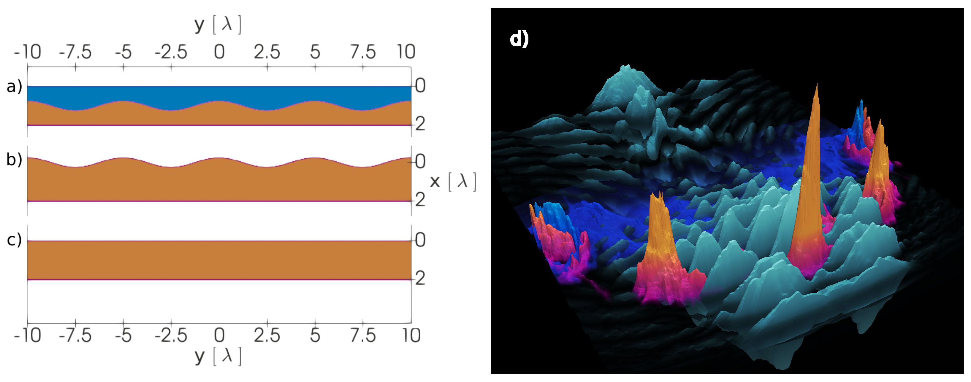
The properties of the ions accelerated from the solid target can be improved by its proper structuring. In our preliminary results in [93], we briefly compared the sinusoidal corrugation on the interface of a double-layer target with the one on the surface of single-layer-target and with the target without a corrugation (see Figure 5a–c).
The corrugation located at the interface of a double-layer target is especially interesting as it resulted in a significant peak in ion spectra (more significant than in the reference case of surface modulation as is briefly discussed in Section 3.3). The interface corrugation was then thoroughly investigated in [41]. Figure 5d contains the visualization of the target density (deuterium: blue, proton: orange) and laser pulse electric field (gray). The values are also represented by the vertical height. The interaction of the laser pulse with the target results in the rise of the relativistic instability, with RTI and RMI features depending on the target geometry. The target is fractured into high density regions (located around the initial corrugation maxima at positions −5 μ m, 0 μ m, and 5 μ m) and low density regions between them (around the initial minima). Moreover, as can be seen in Figure 5d, the laser pulse enfolds the central proton bunch, limiting the bunch broadening in space. Therefore, the ions are accelerated by the radiation pressure as a compact structure, having a low energy spread. The quality and properties of these protons are summarized in Figure 6a–c.
Figure 6a shows the time evolution of the tail of the proton energy spectra. Although the bunch structure is spreading in the later stages, the bunch structure is presented until the end of the simulation. Moreover, the structure is gradually shifting towards the end of the energy spectra with time. The time at 47 T (blue line) is further examined in Figure 6b,c. The average energy of the bunch is 1882 MeV, its bandwidth at FWHM is 67 MeV, and energy spread is about 3.7%. The energy conversion of the laser pulse into the protons inside the bunch is around 3.4%. The conversion into all protons propagating in the forward direction is around 28.7%. The red part of Figure 6b denotes the part of the beam above its FWHM. The angular spectrum of this red part is shown in Figure 6c using the logarithmic scale. The beam is well collimated, with the angular spread 2 θ = 0.65 (at FWHM), the solid angle Ω = 2 π 1 cos θ = 0.1 mrad , the normalized rms transverse emittance [95] ϵ r m s = y 2 p y 2 y p y 2 / m p c = 0.046 mm · mrad , where m p and p y are proton mass and momentum in the y-direction. This emittance is one order of magnitude lower than in the case of conventional proton accelerators [96], but still one order of magnitude higher than the emittance reported in [97] (where the energy range of protons was lower than in our case, up to 10 MeV). The transverse emittance can be also defined in real space via the beam divergence as in [98], yielding emittance ϵ y = 0.218 mm · mrad and divergence Θ d i v = 0.038 rad .
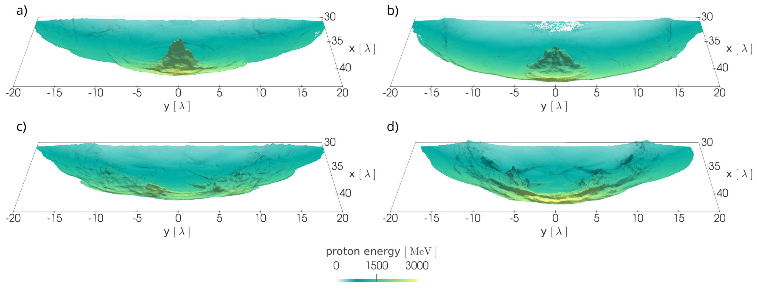
To show the effect of the corrugation, this simulation of the deuterium-proton layer (configuration shown in Figure 5a), denoted as HL (heavy-light), is compared with other simulations. Specifically, simulations of a double-layer target without corrugation (HL-WO), the double-layer target with corrugation, but with opposite order of layers (LH, light-heavy), and the single-layer hydrogen target (L2), (see the details in [41]). Both cases without the corrugation (HL-WO and L2) do not provide a significant peak in the energy spectrum (Figure 6d). The LH case provides a peak but with lower energy and higher energy spread. This behaviors correspond to the proton density shown in Figure 7.
Here, the density is denoted by the vertical height, and the color represents the proton energy at that position. Both simulations with corrugations (Figure 7a,b) generate and maintain the high density bunches influenced by the target geometry as described above. In contrast, the non-corrugated cases (Figure 7c,d) generate a bubble structure typical for RPA acceleration of a planar target [45]. The RPA mechanism then can accelerate a smaller part of the particles at the bubble front to very high energies, but without the desired peak in the proton energy spectra, which is provided by the corrugation.
The influence of different laser polarization and corrugation wavelengths in the HL case is also thoroughly investigated in [41]. The instability leading to bunch generation (and peak in the ion energy spectra) also developed in the case of p-polarization. However, the central bunch was significantly smaller compared to the s-polarization case (shown in this section). This behavior was explained by artificially greater electron heating in the simulation plane in the p-polarization, as previously demonstrated in [89,91]. In contrast, the instability was mitigated in the case of circular polarization, and the ion bunch was not generated. The optimal corrugation wavelength was shown to be around the half of the size of the focal spot, which is used in the simulations in this section.

3.3. Target Stability and Generation of the Steep-Front Laser Pulse

The foil stability is often worsened by the onset of unwanted kinds of instabilities. Especially with the treatment of a relatively short wavelength (independent on the target geometry), transverse instability arising from the laser–target interaction needs to be assumed. This instability is usually ascribed to Rayleigh–Taylor [45,66,67] or electron–ion coupled instability [68,69]. For the sake of brevity and its shorter wavelength compared to the desired instability driving the bunch generation discussed in Section 3.2, this instability will be referred to as short-wavelength instability regardless of its origin hereinafter. Its uncontrolled development results in the lower efficiency of ion acceleration in our case, as the target is shattered into many small bunches, as can be seen in Figure 8a.
As noted in Section 3.1, circular polarization is often used for improving foil stability by mitigation of instabilities. However, circular polarization cannot be applied to our scheme, as it would weaken both the desired and unwanted instabilities, lowering the energy and quality of the proton beam in our simulations (see details about polarization dependence in [41]).
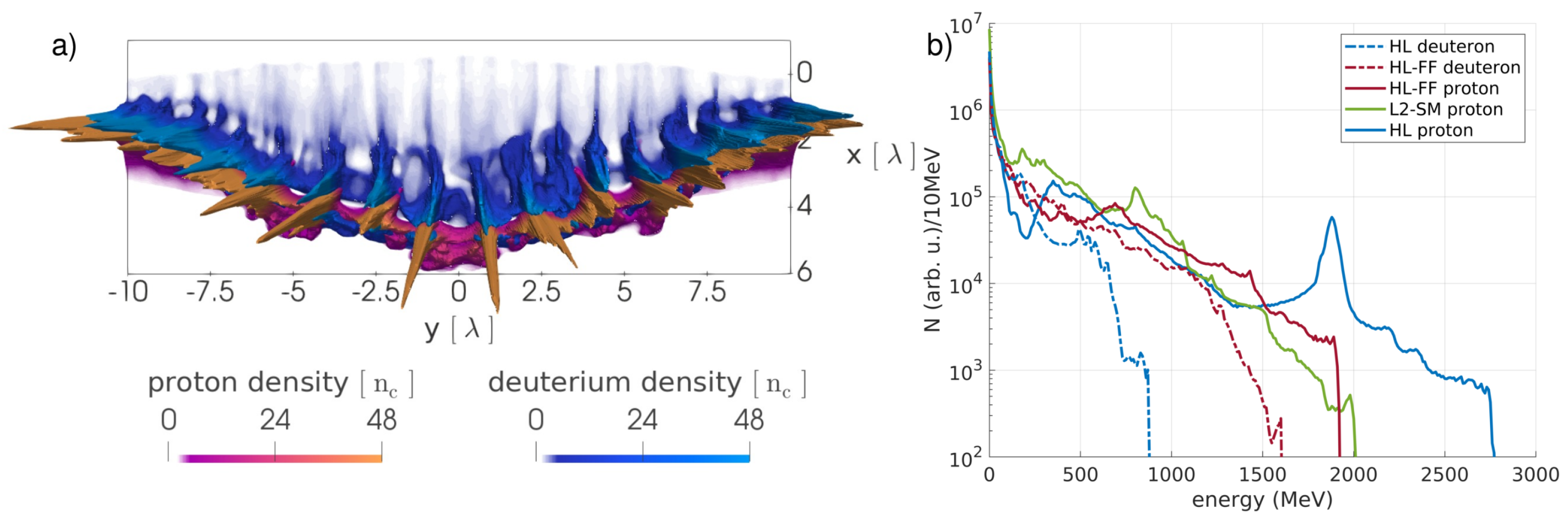
In our simulations, we use a steep-front laser pulse as proposed by theory [45]. Under this condition, the unwanted short-wavelength (RTI-like) instability does not have enough time to significantly develop. On the contrary, the wanted relatively long-wavelength instability induced by the target geometry (with RMI features) can immediately respond to the high radiation pressure and develop properly. This approached was used in all simulations presented in Section 3.2, where the steep-front was simulated by filtering out the beginning of the laser pulse until 2.4 T before the peak of the laser pulse. The simulation shown in Figure 8a represents the uncut full front, being 8 T longer. The effect of the laser front steepness on ion acceleration is shown in the ion energy spectra in Figure 8b. With the use of the full-front laser pulse (HL-FF), the distinctive good-quality peak in the proton spectrum is not developed. A less distinctive, relative broad peak is present, but at significantly lower energy compared to the steep-front case. The proton spectrum is somehow similar to the one of a single-layer hydrogen target with corrugation on its surface (L2-SM, configuration shown in Figure 5b), where the driving instability also originated from the surface. The foil disruption in the HL-FF case also reduces the maximal proton energy. In contrast, the energy of deuterons from the first layer is enhanced compared to the steep-front case, as they are more mixed with the protons.
The required steep-front laser pulse can be generated by several phenomena. If the laser pulse propagates through an underdense plasma [99,100,101] or a near critical density plasma [102,103,104,105,106,107,108], the desired shape can develop through the nonlinear evolution of the laser pulse. Another method is to use a thin overdense plasma foil (usually referred to as a plasma shutter [70,71,72,73,74,75,76,77,78,79]). The front of the laser pulse (with low intensity) is filtered out and the desired (high intensity) part propagates through the foil undergoing relativistic transparency, gaining the steep-front profile. In our further research, we focuses on the plasma shutter technique, first with a PW-class laser pulse utilizing a silicon nitride (Si 3 N 4 ) plasma shutter. The plasma shutter made of this material has several advantages, such as a well defined surface, commercial availability in various thicknesses, and high quality of mechanical and optical properties [109,110]. A visualization of our 3D simulation [78] is shown in Figure 9a.
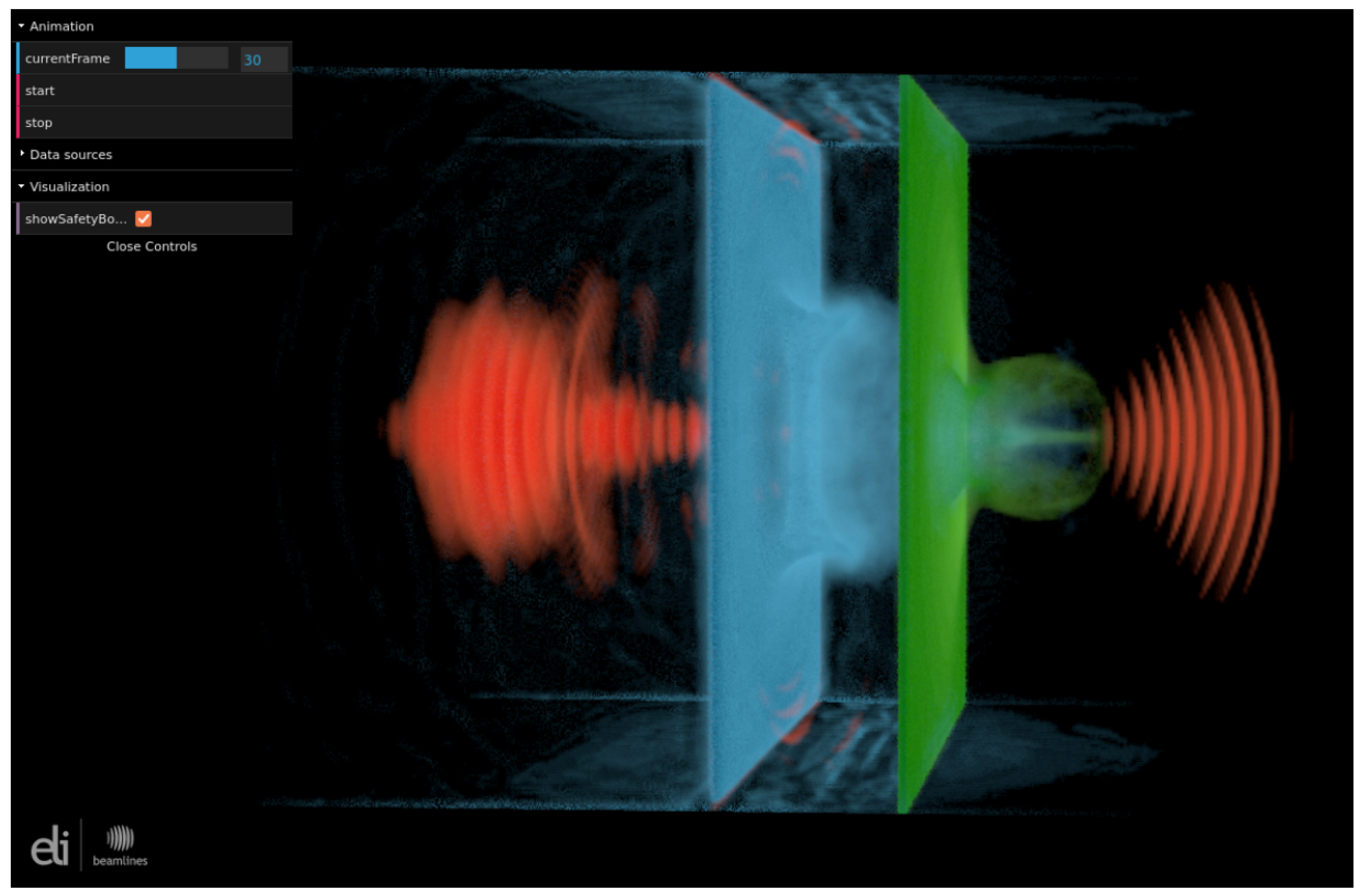
The laser pulse burns through the plasma shutter, shaping its profile and creating the so-called relativistic plasma aperture [111]. Consequently, the laser pulse is diffracted on such an aperture and, due to its constructive interference with generated high harmonics, the local intensity is amplified [78]. Local amplification by a factor of 7 (from the initial intensity of 1 × 10 22 W / cm 2 ) can be seen in the highlighted area of Figure 9a, where the 2D profile of the laser pulse intensity in the polarization plane (x-y) is shown. Figure 9b shows the 1D profile (at the center of the pulse) at a later time, when the envelope stabilizes [76]. The blue line represents the original pulse in the simulation without the plasma shutter (W/O-Sh), and the red line is from the simulation with the plasma shutter (W/1xSh). The pulse front is about five periods shorter and significantly steeper compared to the original pulse. The maximal amplitude of this central (1D) profile is also enhanced, although the main intensity amplification occurs off-axis, as shown in Figure 9a. The application of the produced laser pulse for ion acceleration from a silver target was briefly investigated, with the preliminary results in [76], and then thoroughly discussed in [79], where the position of the target was also optimized. The setup of this 3D simulation is shown in our VR application in Figure 10, where the laser pulse (incoming from the left) is represented by the red color scale, electron density of the shutter is represented by the blue scale, and the density of silver ions from the target are represented by the green scale.
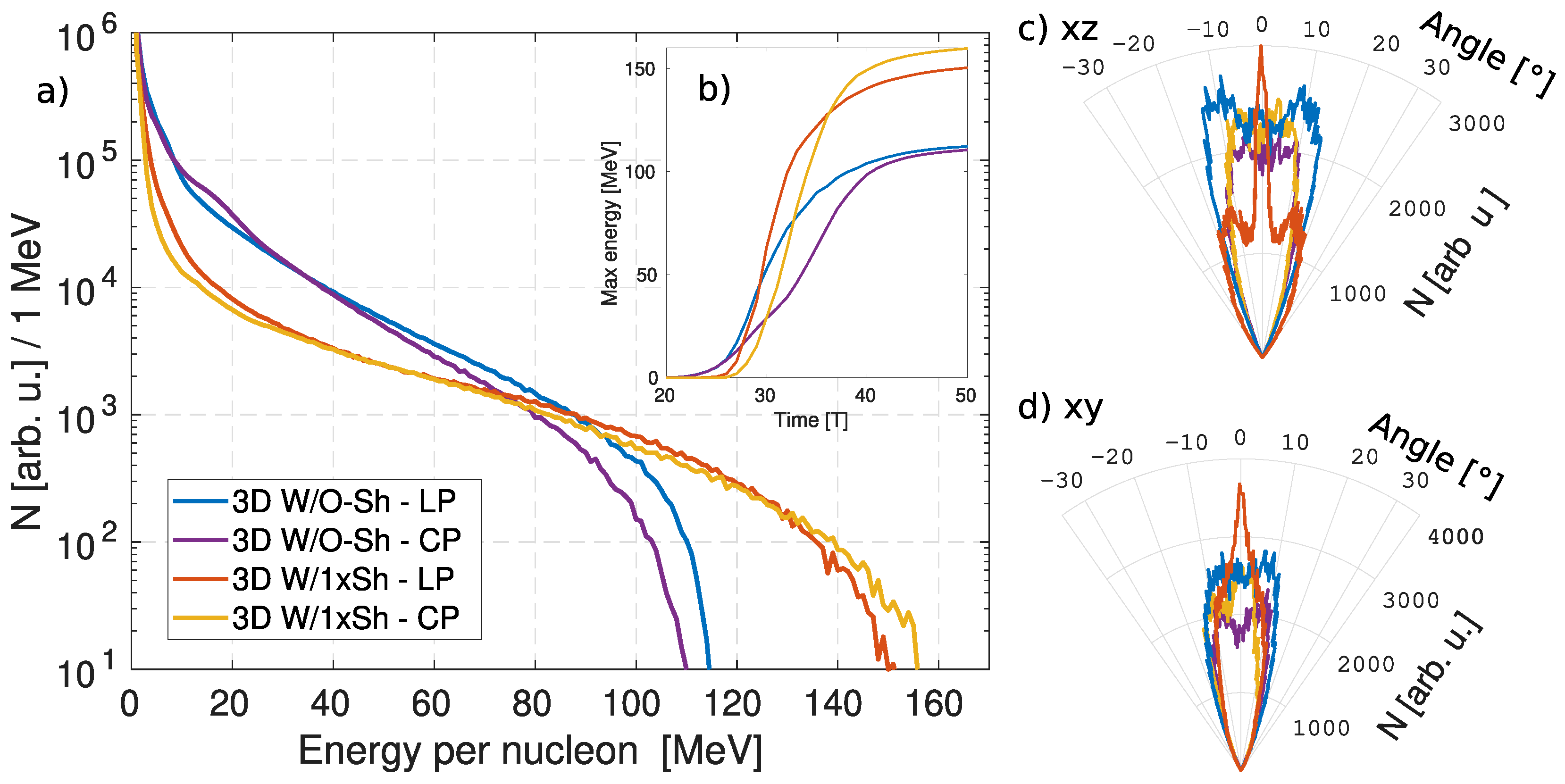
The use of the plasma shutter can result in an increase in maximal energy of heavy ions, as shown in Figure 11a, although a part of the laser pulse energy is lost during the development of the aperture [79]. For the linear polarization, the maximal energy of silver ions at the end of the simulation increases from 115 to 155 MeV per nucleon (about 35%) when the plasma shutter is included in the simulation. The same effect is also observed for the circular polarization, where the maximal energy increase is even slightly higher (about 44%). Moreover, in the case of linear polarization, the divergence of the accelerated ion beam in the x-z plane (Figure 11c) significantly decreases as the ions are focused towards the laser axis in the plane perpendicular to the laser polarization. This beam-like structure is visible in Figure 10 behind the silver target (green color) around the laser axis. The shutter also has a positive effect on the beam divergence in the xy plane, as shown in Figure 11d; this effect was ascribed to the steep-front generation. The transverse instability in ion density (similar to the instability in Figure 8a) is also reduced when the shutter is included (and the steep-front is generated); see the full discussion in [79]. This finding corresponds to the results discussed above. In addition, two (or a series of) plasma shutters can be used to mitigate the prepulses accompanying the main pulse, thus also improving the laser contrast. The double-shutter scenario was investigated using a combination of 2D PIC and hydrodynamic simulations in [79]. The first shutter can withstand the assumed sub-ns prepulse (treatment of ns and ps prepulses by other techniques is assumed; alternatively increasing the thickness of the first shutter may filter out longer prepulses), whereas the steep front generation and the local intensity increase occurred via interaction with the second non-expanded shutter. The increase in the maximal ion energy compared to the 2D simulation without any shutter is also demonstrated in this case. A prototype of such a double shutter is presented and the design of the whole shutter-target setup is discussed in [79].
According to our findings, the plasma shutter provides a promising possible solution to the question of target stability via steep-front laser pulse generation. However, further research and optimization is required for its application for the interaction of 100 PW class lasers with double-layer targets.

4. Discussion

In this work, we review our results on the prospect of improving the quality and properties of protons accelerated by future laser systems using cryogenic targets. It is shown that, for these low density targets, the RPA mechanism can become the dominant acceleration regime. The domination is stronger with increasing laser intensity. The use of structured double-layered targets with interface corrugation in our simulations results in the occurrence of a relativistic instability influenced by the target geometry. Its development leads to the generation of a high-density and high-energy proton bunch. This bunch is accelerated by the dominant RPA mechanism as a compact structure, resulting in a proton beam of high quality. It includes low divergence, transverse emittance, and energy spread of accelerated protons. This beam is not developed in the reference cases without the corrugation on the target interface.
We further discuss the stability of this laser–target interaction. Another instability arising rather from the laser interaction with the target surface (with shorter wavelength compared to the interface corrugation assumed) needs to be reduced in order to generate the high-quality proton bunch. It is shown that the development of this short-wavelength instability is mitigated using a steep-front laser pulse. We propose the use of the plasma shutter to obtain the required laser pulse shape. Although a part of the laser pulse energy would be lost, the transmitted laser pulse will gain the steep-front time profile and locally increase the peak pulse intensity. This concept has been shown advantageous for ion acceleration using a PW-class laser pulse, improving both the maximal ion energy and beam properties [79].
The optimization of shutter parameters for use with the structured targets and laser systems with higher power assumed in this work will require additional research. The fully 3D simulation of this concept will be performed in the future.

Author Contributions

M.M. wrote the bulk of the manuscript, carried out most of the the simulations, and analyzed the results; J.P. carried out the 3D simulations in Section 3.1; K.N. contributed by determining simulation parameters and analysis of the instability in Section 3.2; M.J. analyzed and visualized the data of the plasma shutter in Figure 9a; P.V. helped to prepare the appendix about virtual reality; O.K. helped with the analysis of results regarding the plasma shutter in Section 3.3; S.V.B. provided overall supervision. All the authors have contributed to preparation and correction of this paper. All authors have read and agreed to the published version of the manuscript.

Funding

Portions of this research were carried out at ELI Beamlines, a European user facility operated by the Institute of Physics of the Academy of Sciences of the Czech Republic. Our work is supported by projects High Field Initiative (CZ.02.1.01/0.0/0.0/15_003/0000449) and Center of Advanced Applied Sciences (CZ.02.1.01/0.0/0.0/16_019/0000778) from the European Regional Development Fund. This work was supported by the Ministry of Education, Youth and Sports of the Czech Republic through the e-INFRA CZ (ID:90140). The support of Grant Agency of the Czech Technical University in Prague is appreciated, grant no. SGS22/185/OHK4/3T/14.

Data Availability Statement

The datasets generated and analyzed during the current study are available from the corresponding author on reasonable request.

Acknowledgments

We appreciate the collaboration with Virtual Beamline team of ELI Beamlines Centre, namely M. Kecova, P. Janecka, and J. Grosz with the work done towards the virtual reality visualization of our results. The discussions with G. Korn from ELI Beamlines are appreciated.

Conflicts of Interest

The authors declare no conflict of interest.

Abbreviations

The following abbreviations are used in this manuscript:
RPARadiation Pressure Acceleration
TNSATarget Normal Sheath Acceleration
RTIRayleigh–Taylor Instability
RMIRichtmyer–Meshkov Instability
HLHeavy-Light
LHLight-Heavy
HL-WOHL without Modulation
L2Light Single-Layer with the Same Thickness as HL
HL-FFHL with Full-Front Laser Pulse
L2-SML2 with Surface Modulation
W/O-ShWithout Plasma Shutter
W/1xShWith Plasma Shutter
VBLVirtual BeamLine
VRVirtual Reality

Appendix A. Virtual Reality Visualization

Virtual reality (VR) technology is receiving more and more attention in the field of scientific visualization. It utilizes computational power and human–machine interaction concepts to emulate the effect of a 3D world. The audience uses a VR headset (i.e., a device worn on the head having small display(s), with embedded lenses and semi-transparent mirrors) and VR controllers to interact with the objects representing the scientific datasets and explore their complicated spatial and temporal structures in a way that makes them easy to understand.
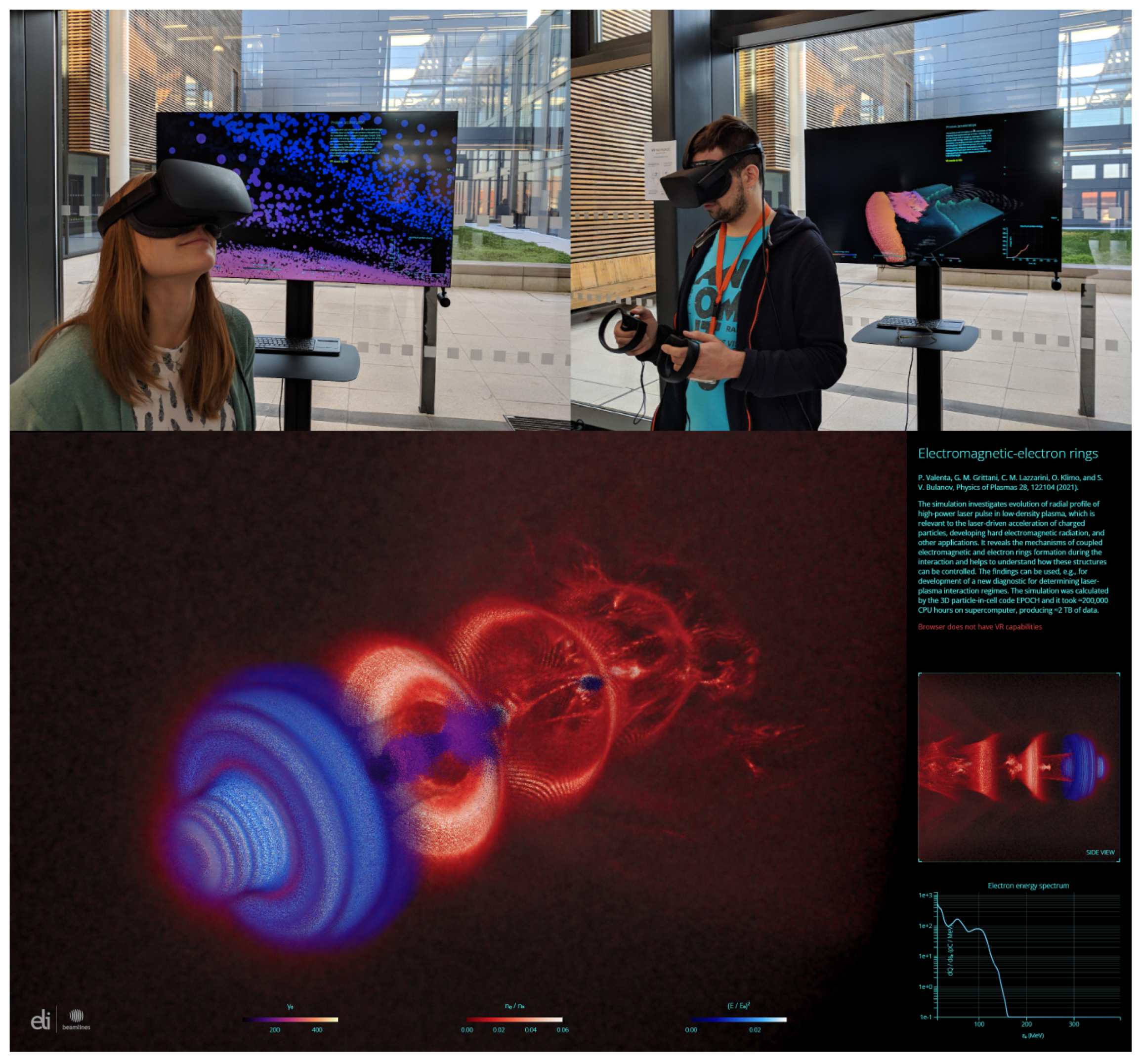
At ELI Beamlines, we use a custom WebGL [113] render solution in the form of a complex web client–server application running inside a regular web browser. The application, called Virtual Beamline—VBL [114], renders the output of interactive visualization in real time (i.e., at sufficiently high frame rates) to user’s regular and VR displays. The VBL application has been used not only for research itself, but also for educational purposes and science popularization. The use of the VR stations located at the atrium of ELI Beamlines is shown in the upper part of Figure A1, running the visualization discussed in Section 3.1.
The VBL application can visualize multi-dimensional mesh- and particle-based data that may be obtained from computer simulations or experimental measurements. The raw data must be preprocessed and converted to binary buffers that the application can read. At this point, one should also ensure that the size of the processed data complies with the capabilities of the machine used for the visualization. Finally, the resulting buffers together with a scene description in a form of a JSON [115] file are stored on a web server acting as a data input for the visualization engine of the VBL application. More details about the VBL application can be found in [85].
As can be seen in Figure A1, the application window contains multiple viewports that may show, apart from the full 3D view, the data projections along a certain plane or axis, time-dependent plots of a selected parameter, textual and numerical data, etc. On top of that, there is an additional layer containing a description of displayed dataset as well as a graphical user interface (GUI). It utilizes d3.js library for graphical elements and dat.GUI library for the interface providing animation control and layer visibility management. GUI controls together with VR controllers enable users to interact with a displayed scene by moving and scaling it in the 3D space, filtering its content, and navigating in the animation timeline.
The bottom part of Figure A1 shows an example of a visualization based on the 3D PIC simulation data. The simulation investigates evolution of the radial profile of a high-power laser pulse in a low-density plasma [116]. The VBL application helped considerably to reveal the mechanisms of coupled electromagnetic and electron rings formation during the interaction and to understand how these structures can be controlled. The simulation was calculated by the EPOCH code [80]; it took ≈ 2 × 10 5 core-hours, producing ≈ 2 TB of raw data. The final size of the data processed for the purpose of the visualization in the VBL application is ≈ 10 GB . The interactive visualization is available online [117] (note that the client device is required to have at least 16 GB of free memory and the VR mode has been tested for Oculus Rift in Firefox). The visualization shown in Figure 3 and the upper part of Figure A1 has lower size (as it is based on 2D simulation) and is available online [84]. Other visualizations made at ELI Beamlines can be viewed online [114], including the shutter visualization [112] from Figure 10.
Figure A1. VBL application. (top) The use of the VBL application on the VR stations at ELI Beamlines (photo from [83]). (bottom) Example of a visualization based on the 3D PIC simulation data [116] using the VBL application.
Photonics 10 00061 g0a1

References

  1. Bulanov, S.V.; Esirkepov, T.; Khoroshkov, V.S.; Kuznetsov, A.V.; Pegoraro, F. Oncological hadrontherapy with laser ion accelerators. Phys. Lett. A 2002, 299, 240–247. [Google Scholar] [CrossRef]
  2. Bulanov, S.V.; Wilkens, J.J.; Esirkepov, T.Z.; Korn, G.; Kraft, G.; Kraft, S.D.; Molls, M.; Khoroshkov, V.S. Laser ion acceleration for hadron therapy. Physics-Uspekhi 2014, 57, 1149–1179. [Google Scholar] [CrossRef]
  3. Tajima, T. Prospect for compact medical laser accelerators. J. Jpn. Soc. Therap. Radiol. Oncol. 1997, 9, 83–85. [Google Scholar]
  4. Roth, M.; Cowan, T.E.; Key, M.H.; Hatchett, S.P.; Brown, C.; Fountain, W.; Johnson, J.; Pennington, D.M.; Snavely, R.A.; Wilks, S.C.; et al. Fast ignition by intense laser-accelerated proton beams. Phys. Rev. Lett. 2001, 86, 436–439. [Google Scholar] [CrossRef] [PubMed]
  5. Atzeni, S.; Temporal, M.; Honrubia, J.J. A first analysis of fast ignition of precompressed ICF fuel by laser-accelerated protons. Nucl. Fusion 2002, 42, L1. [Google Scholar] [CrossRef]
  6. Nishiuchi, M.; Sakaki, H.; Esirkepov, T.Z.; Nishio, K.; Pikuz, T.A.; Faenov, A.Y.; Skobelev, I.Y.; Orlandi, R.; Sako, H.; Pirozhkov, A.S.; et al. Acceleration of highly charged GeV Fe ions from a low-Z substrate by intense femtosecond laser. Phys. Plasmas 2015, 22, 033107. [Google Scholar] [CrossRef]
  7. Daido, H.; Nishiuchi, M.; Pirozhkov, A.S. Review of laser-driven ion sources and their applications. Rep. Prog. Phys. 2012, 75, 056401. [Google Scholar] [CrossRef]
  8. Macchi, A.; Borghesi, M.; Passoni, M. Ion acceleration by superintense laser-plasma interaction. Rev. Mod. Phys. 2013, 85, 751–793. [Google Scholar] [CrossRef] [Green Version]
  9. Passoni, M.; Arioli, F.M.; Cialfi, L.; Dellasega, D.; Fedeli, L.; Formenti, A.; Giovannelli, A.C.; Maffini, A.; Mirani, F.; Pazzaglia, A.; et al. Advanced laser-driven ion sources and their applications in materials and nuclear science. Plasma Phys. Control. Fusion 2019, 62, 014022. [Google Scholar] [CrossRef]
  10. Garcia, S.; Chatain, D.; Perin, J.P. Continuous production of a thin ribbon of solid hydrogen. Laser Part. Beams 2014, 32, 569–575. [Google Scholar] [CrossRef]
  11. Margarone, D.; Velyhan, A.; Dostal, J.; Ullschmied, J.; Perin, J.P.; Chatain, D.; Garcia, S.; Bonnay, P.; Pisarczyk, T.; Dudzak, R.; et al. Proton acceleration driven by a nanosecond laser from a cryogenic thin solid-hydrogen ribbon. Phys. Rev. X 2016, 6, 041030. [Google Scholar] [CrossRef]
  12. Margarone, D.; Cirrone, G.A.P.; Cuttone, G.; Amico, A.; Andò, L.; Borghesi, M.; Bulanov, S.S.; Bulanov, S.V.; Chatain, D.; Fajstavr, A.; et al. ELIMAIA: A Laser-Driven Ion Accelerator for Multidisciplinary Applications. Quantum Beam Sci. 2018, 2, 8. [Google Scholar] [CrossRef] [Green Version]
  13. Chagovets, T.; Stanček, S.; Giuffrida, L.; Velyhan, A.; Tryus, M.; Grepl, F.; Istokskaia, V.; Kantarelou, V.; Wiste, T.; Hernandez Martin, J.; et al. & Margarone, D. Automation of Target Delivery and Diagnostic Systems for High Repetition Rate Laser-Plasma Acceleration. Appl. Sci. 2021, 11, 1680. [Google Scholar] [CrossRef]
  14. Weber, S.; Bechet, S.; Borneis, S.; Brabec, L.; Bučka, M.; Chacon-Golcher, E.; Ciappina, M.; DeMarco, M.; Fajstavr, A.; Falk, K.; et al. P3: An installation for high-energy density plasma physics and ultra-high intensity laser–matter interaction at ELI-Beamlines. Matter Radiat. Extrem. 2017, 2, 149–176. [Google Scholar] [CrossRef] [Green Version]
  15. Condamine, F.P.; Jourdain, N.; Hernandez, J.C.; Taylor, M.; Bohlin, H.; Fajstavr, A.; Jeong, T.M.; Kumar, D.; Laštovička, T.; Renner, O.; et al. High-repetition rate solid target delivery system for PW-class laser–matter interaction at ELI Beamlines. Rev. Sci. Instrum. 2021, 92, 063504. [Google Scholar] [CrossRef]
  16. Jourdain, N.; Chaulagain, U.; Havlík, M.; Kramer, D.; Kumar, D.; Majerová, I.; Tikhonchuk, V.T.; Korn, G.; Weber, S. The L4n laser beamline of the P3-installation: Towards high-repetition rate high-energy density physics at ELI-Beamlines. Matter Radiat. Extrem. 2021, 6, 015401. [Google Scholar] [CrossRef]
  17. Papadopoulos, D.; Zou, J.; Le Blanc, C.; Cheriaux, G.; Georges, P.; Druon, F.; Mennerat, G.; Martin, L.; Fréneaux, A.; Beluze, A.; et al. The Apollon 10 PW laser: Experimental and theoretical investigation of the temporal characteristics. High Power Laser Sci. Eng. 2016, 4, E34. [Google Scholar] [CrossRef]
  18. Zamfir, N.V. Nuclear Physics with 10 PW laser beams at Extreme Light Infrastructure-Nuclear Physics (ELI-NP). Eur. Phys. J. Spec. Top. 2014, 223, 1221–1227. [Google Scholar] [CrossRef]
  19. Shao, B.; Li, Y.; Peng, Y.; Wang, P.; Qian, J.; Leng, Y.; Li, R. Broad-bandwidth high-temporal-contrast carrier-envelope-phase-stabilized laser seed for 100 PW lasers. Opt. Lett. 2020, 45, 2215–2218. [Google Scholar] [CrossRef]
  20. Esirkepov, T.; Borghesi, M.; Bulanov, S.V.; Mourou, G.; Tajima, T. Highly efficient relativistic-ion generation in the laser-piston regime. Phys. Rev. Lett. 2004, 92, 175003. [Google Scholar] [CrossRef] [Green Version]
  21. Wilks, S.C.; Langdon, A.B.; Cowan, T.E.; Roth, M.; Singh, M.; Hatchett, S.; Key, M.H.; Pennington, D.; MacKinnon, A.; Snavely, R.A. Energetic proton generation in ultra-intense laser–solid interactions. Phys. Plasmas 2001, 8, 542–549. [Google Scholar] [CrossRef]
  22. Snavely, R.A.; Key, M.H.; Hatchett, S.P.; Cowan, T.E.; Roth, M.; Phillips, T.W.; Stoyer, M.A.; Henry, E.A.; Sangster, T.C.; Singh, M.S.; et al. Intense High-Energy Proton Beams from Petawatt-Laser Irradiation of Solids. Phys. Rev. Lett. 2000, 85, 2945–2948. [Google Scholar] [CrossRef] [PubMed]
  23. Psikal, J.; Matys, M. Dominance of hole-boring radiation pressure acceleration regime with thin ribbon of ionized solid hydrogen. Plasma Phys. Control. Fusion 2018, 60, 044003. [Google Scholar] [CrossRef] [Green Version]
  24. Macchi, A.; Cattani, F.; Liseykina, T.V.; Cornolti, F. Laser Acceleration of Ion Bunches at the Front Surface of Overdense Plasmas. Phys. Rev. Lett. 2005, 94, 165003. [Google Scholar] [CrossRef] [Green Version]
  25. Schwoerer, H.; Pfotenhauer, S.; Jäckel, O.; Amthor, K.U.; Liesfeld, B.; Ziegler, W.; Sauerbrey, R.; Ledingham, K.W.D.; Esirkepov, T. Laser-plasma acceleration of quasi-monoenergetic protons from microstructured targets. Nature 2006, 439, 445–448. [Google Scholar] [CrossRef] [PubMed]
  26. Hegelich, B.M.; Albright, B.J.; Cobble, J.; Flippo, K.; Letzring, S.; Paffett, M.; Ruhl, H.; Schreiber, J.; Schulze, R.K.; Fernández, J.C. Laser acceleration of quasi-monoenergetic MeV ion beams. Nature 2006, 439, 441–444. [Google Scholar] [CrossRef] [Green Version]
  27. Kar, S.; Borghesi, M.; Bulanov, S.V.; Key, M.H.; Liseykina, T.V.; Macchi, A.; Mackinnon, A.J.; Patel, P.K.; Romagnani, L.; Schiavi, A.; et al. Plasma Jets Driven by Ultraintense-Laser Interaction with Thin Foils. Phys. Rev. Lett. 2008, 100, 225004. [Google Scholar] [CrossRef] [Green Version]
  28. Henig, A.; Steinke, S.; Schnürer, M.; Sokollik, T.; Hörlein, R.; Kiefer, D.; Jung, D.; Schreiber, J.; Hegelich, B.M.; Yan, X.Q.; et al. Radiation-Pressure Acceleration of Ion Beams Driven by Circularly Polarized Laser Pulses. Phys. Rev. Lett. 2009, 103, 245003. [Google Scholar] [CrossRef] [Green Version]
  29. Kar, S.; Kakolee, K.F.; Qiao, B.; Macchi, A.; Cerchez, M.; Doria, D.; Geissler, M.; McKenna, P.; Neely, D.; Osterholz, J.; et al. Ion Acceleration in Multispecies Targets Driven by Intense Laser Radiation Pressure. Phys. Rev. Lett. 2012, 109, 185006. [Google Scholar] [CrossRef] [Green Version]
  30. Kim, I.J.; Pae, K.H.; Choi, I.W.; Lee, C.L.; Kim, H.T.; Singhal, H.; Sung, J.H.; Lee, S.K.; Lee, H.W.; Nickles, P.V.; et al. Radiation pressure acceleration of protons to 93 MeV with circularly polarized petawatt laser pulses. Phys. Plasmas 2016, 23, 070701. [Google Scholar] [CrossRef]
  31. Henig, A.; Kiefer, D.; Markey, K.; Gautier, D.C.; Flippo, K.A.; Letzring, S.; Johnson, R.P.; Shimada, T.; Yin, L.; Albright, B.J.; et al. Enhanced Laser-Driven Ion Acceleration in the Relativistic Transparency Regime. Phys. Rev. Lett. 2009, 103, 045002. [Google Scholar] [CrossRef] [PubMed]
  32. Yan, X.Q.; Lin, C.; Sheng, Z.M.; Guo, Z.Y.; Liu, B.C.; Lu, Y.R.; Fang, J.X.; Chen, J.E. Generating High-Current Monoenergetic Proton Beams by a CircularlyPolarized Laser Pulse in the Phase-StableAcceleration Regime. Phys. Rev. Lett. 2008, 100, 135003. [Google Scholar] [CrossRef] [PubMed]
  33. Yan, X.Q.; Tajima, T.; Hegelich, M.; Yin, L.; Habs, D. Theory of laser ion acceleration from a foil target of nanometer thickness. Appl. Phys. B 2009, 98, 711–721. [Google Scholar] [CrossRef] [Green Version]
  34. Tajima, T.; Habs, D.; Yan, X. Laser Acceleration of Ions for Radiation Therapy; World Scientific: Singapore, 2009; pp. 201–228. [Google Scholar] [CrossRef]
  35. Naumova, N.; Schlegel, T.; Tikhonchuk, V.T.; Labaune, C.; Sokolov, I.V.; Mourou, G. Hole Boring in a DT Pellet and Fast-Ion Ignition with Ultraintense Laser Pulses. Phys. Rev. Lett. 2009, 102, 025002. [Google Scholar] [CrossRef] [PubMed] [Green Version]
  36. Robinson, A.P.L.; Gibbon, P.; Zepf, M.; Kar, S.; Evans, R.G.; Bellei, C. Relativistically correct hole-boring and ion acceleration by circularly polarized laser pulses. Plasma Phys. Control. Fusion 2009, 51, 024004. [Google Scholar] [CrossRef]
  37. Bulanov, S.V.; Esirkepov, T.Z.; Kando, M.; Pegoraro, F.; Bulanov, S.S.; Geddes, C.G.R.; Schroeder, C.B.; Esarey, E.; Leemans, W.P. Ion acceleration from thin foil and extended plasma targets by slow electromagnetic wave and related ion-ion beam instability. Phys. Plasmas 2012, 19, 103105. [Google Scholar] [CrossRef]
  38. Macchi, A.; Veghini, S.; Pegoraro, F. “Light Sail” Acceleration Reexamined. Phys. Rev. Lett. 2009, 103, 085003. [Google Scholar] [CrossRef]
  39. Mackenroth, F.; Bulanov, S.S. Tailored laser pulse chirp to maintain optimum radiation pressure acceleration of ions. Phys. Plasmas 2019, 26, 023103. [Google Scholar] [CrossRef] [Green Version]
  40. Kar, S.; Kakolee, K.F.; Cerchez, M.; Doria, D.; Macchi, A.; McKenna, P.; Neely, D.; Osterholz, J.; Quinn, K.; Ramakrishna, B.; et al. Experimental investigation of hole boring and light sail regimes of RPA by varying laser and target parameters. Plasma Phys. Control. Fusion 2013, 55, 124030. [Google Scholar] [CrossRef] [Green Version]
  41. Matys, M.; Nishihara, K.; Kecova, M.; Psikal, J.; Korn, G.; Bulanov, S.V. Laser-driven generation of collimated quasi-monoenergetic proton beam using double-layer target with modulated interface. High Energy Density Phys. 2020, 36, 100844. [Google Scholar] [CrossRef]
  42. Bulanov, S.V.; Khoroshkov, V.S. Feasibility of using laser ion accelerators in proton therapy. Plasma Phys. Rep. 2002, 28, 453–456. [Google Scholar] [CrossRef]
  43. Bulanov, S.V.; Esirkepov, T.Z.; Kamenets, F.F.; Kato, Y.; Kuznetsov, A.V.; Nishihara, K.; Pegoraro, F.; Tajima, T.; Khoroshkov, V.S. Generation of high-quality charged particle beams during the acceleration of ions by high-power laser radiation. Plasma Phys. Rep. 2002, 28, 975–991. [Google Scholar] [CrossRef]
  44. Esirkepov, T.; Bulanov, S.V.; Nishihara, K.; Tajima, T.; Pegoraro, F.; Khoroshkov, V.S.; Mima, K.; Daido, H.; Kato, Y.; Kitagawa, Y.; et al. Proposed double-layer target for the generation of high-quality laser-accelerated ion beams. Phys. Rev. Lett. 2002, 89, 175003. [Google Scholar] [CrossRef] [PubMed]
  45. Pegoraro, F.; Bulanov, S.V. Photon bubbles and ion acceleration in a plasma dominated by the radiation pressure of an electromagnetic pulse. Phys. Rev. Lett. 2007, 99, 065002. [Google Scholar] [CrossRef] [Green Version]
  46. Echkina, E.Y.; Inovenkov, I.N.; Esirkepov, T.Z.; Pegoraro, F.; Borghesi, M.; Bulanov, S.V. Dependence of the ion energy on the parameters of the laser pulse and target in the radiation-pressure-dominated regime of acceleration. Plasma Phys. Rep. 2010, 36, 15–29. [Google Scholar] [CrossRef]
  47. Lord Rayleigh. Investigation of the character of the equilibrium of an incompressible heavy fluid of variable density. Proc. Lond. Math. Soc. 1882, 14, 170–177. [Google Scholar] [CrossRef]
  48. Taylor, G. The instability of liquid surfaces when accelerated in a direction perpendicular to their planes. I. Proc. R. Soc. Lond. Ser. A Math. Phys. Sci. 1950, 201, 192–196. [Google Scholar] [CrossRef]
  49. Richtmyer, R.D. Taylor instability in shock acceleration of compressible fluids. Commun. Pure Appl. Math. 1960, 13, 297–319. [Google Scholar] [CrossRef]
  50. Meshkov, E.E. Instability of the interface of two gases accelerated by a shock wave. Fluid Dyn. 1969, 4, 101–104. [Google Scholar] [CrossRef]
  51. Zhou, Y. Rayleigh–Taylor and Richtmyer–Meshkov instability induced flow, turbulence, and mixing. I. Phys. Rep. 2017, 720–722, 1–136. [Google Scholar] [CrossRef]
  52. Palmer, C.A.; Schreiber, J.; Nagel, S.R.; Dover, N.P.; Bellei, C.; Beg, F.N.; Bott, S.; Clarke, R.J.; Dangor, A.E.; Hassan, S.M.; et al. Rayleigh-Taylor instability of an ultrathin foil accelerated by the radiation pressure of an intense laser. Phys. Rev. Lett. 2012, 108, 225002. [Google Scholar] [CrossRef] [PubMed]
  53. Yang, Y.; Zhang, Q.; Sharp, D.H. Small amplitude theory of Richtmyer-Meshkov instability. Phys. Fluids 1994, 6, 1856–1873. [Google Scholar] [CrossRef]
  54. Wouchuk, J.G.; Nishihara, K. Asymptotic growth in the linear Richtmyer-Meshkov instability. Phys. Plasmas 1997, 4, 1028–1038. [Google Scholar] [CrossRef] [Green Version]
  55. Nishihara, K.; Wouchuk, J.G.; Matsuoka, C.; Ishizaki, R.; Zhakhovsky, V.V. Richtmyer-Meshkov instability: Theory of linear and nonlinear evolution. Philos. Trans. R. Soc. A Math. Phys. Eng. Sci. 2010, 368, 1769–1807. [Google Scholar] [CrossRef] [PubMed]
  56. Mohseni, F.; Mendoza, M.; Succi, S.; Herrmann, H.J. Relativistic effects on the Richtmyer-Meshkov instability. Phys. Rev. D Part. Fields Gravit. Cosmol. 2014, 90, 125028. [Google Scholar] [CrossRef] [Green Version]
  57. Matsuoka, C.; Nishihara, K.; Sano, T. Nonlinear Dynamics of Non-uniform Current-Vortex Sheets in Magnetohydrodynamic Flows. J. Nonlinear Sci. 2017, 27, 531–572. [Google Scholar] [CrossRef] [Green Version]
  58. Zhou, Y.; Clark, T.T.; Clark, D.S.; Gail Glendinning, S.; Aaron Skinner, M.; Huntington, C.M.; Hurricane, O.A.; Dimits, A.M.; Remington, B.A. Turbulent mixing and transition criteria of flows induced by hydrodynamic instabilities. Phys. Plasmas 2019, 26, 080901. [Google Scholar] [CrossRef]
  59. Zhou, Y.; Williams, R.J.; Ramaprabhu, P.; Groom, M.; Thornber, B.; Hillier, A.; Mostert, W.; Rollin, B.; Balachandar, S.; Powell, P.D.; et al. Rayleigh–Taylor and Richtmyer–Meshkov instabilities: A journey through scales. Phys. D Nonlinear Phenom. 2021, 423, 132838. [Google Scholar] [CrossRef]
  60. Hester, J.J. The Crab Nebula: An Astrophysical Chimera. Annu. Rev. Astron. Astrophys. 2008, 46, 127–155. [Google Scholar] [CrossRef] [Green Version]
  61. Lindl, J.D.; Mccrory, R.L.; Campbell, E.M. Progress toward Ignition and Burn Propagation in Inertial Confinement Fusion. Phys. Today 1992, 45, 32–40. [Google Scholar] [CrossRef]
  62. Waddell, J.T.; Niederhaus, C.E.; Jacobs, J.W. Experimental study of Rayleigh–Taylor instability: Low Atwood number liquid systems with single-mode initial perturbations. Phys. Fluids 2001, 13, 1263–1273. [Google Scholar] [CrossRef]
  63. Niederhaus, C.E.; Jacobs, J.W. Experimental study of the Richtmyer-Meshkov instability of incompressible fluids. J. Fluid Mech. 2003, 485, 243–277. [Google Scholar] [CrossRef] [Green Version]
  64. Velikovich, A.L. Analytic theory of Richtmyer-Meshkov instability for the case of reflected rarefaction wave. Phys. Fluids 1996, 8, 1666–1679. [Google Scholar] [CrossRef]
  65. Wouchuk, J.G.; Nishihara, K. Linear perturbation growth at a shocked interface. Phys. Plasmas 1996, 3, 3761–3776. [Google Scholar] [CrossRef] [Green Version]
  66. Klimo, O.; Psikal, J.; Limpouch, J.; Tikhonchuk, V.T. Monoenergetic ion beams from ultrathin foils irradiated by ultrahigh-contrast circularly polarized laser pulses. Phys. Rev. Spec. Top. Accel. Beams 2008, 11, 031301. [Google Scholar] [CrossRef] [Green Version]
  67. Robinson, A.P.; Zepf, M.; Kar, S.; Evans, R.G.; Bellei, C. Radiation pressure acceleration of thin foils with circularly polarized laser pulses. New J. Phys. 2008, 10, 013021. [Google Scholar] [CrossRef]
  68. Wan, Y.; Pai, C.H.; Zhang, C.J.; Li, F.; Wu, Y.P.; Hua, J.F.; Lu, W.; Gu, Y.Q.; Silva, L.O.; Joshi, C.; et al. Physical Mechanism of the Transverse Instability in Radiation Pressure Ion Acceleration. Phys. Rev. Lett. 2016, 117, 234801. [Google Scholar] [CrossRef] [Green Version]
  69. Wan, Y.; Pai, C.H.; Zhang, C.J.; Li, F.; Wu, Y.P.; Hua, J.F.; Lu, W.; Joshi, C.; Mori, W.B.; Malka, V. Physical mechanism of the electron-ion coupled transverse instability in laser pressure ion acceleration for different regimes. Phys. Rev. E 2018, 98, 013202. [Google Scholar] [CrossRef]
  70. Vshivkov, V.A.; Naumova, N.M.; Pegoraro, F.; Bulanov, S.V. Nonlinear electrodynamics of the interaction of ultra-intense laser pulses with a thin foil. Phys. Plasmas 1998, 5, 2727–2741. [Google Scholar] [CrossRef]
  71. Reed, S.A.; Matsuoka, T.; Bulanov, S.; Tampo, M.; Chvykov, V.; Kalintchenko, G.; Rousseau, P.; Yanovsky, V.; Kodama, R.; Litzenberg, D.W.; et al. Relativistic plasma shutter for ultraintense laser pulses. Appl. Phys. Lett. 2009, 94, 201117. [Google Scholar] [CrossRef]
  72. Palaniyappan, S.; Hegelich, B.M.; Wu, H.C.; Jung, D.; Gautier, D.C.; Yin, L.; Albright, B.J.; Johnson, R.P.; Shimada, T.; Letzring, S.; et al. Dynamics of relativistic transparency and optical shuttering in expanding overdense plasmas. Nat. Phys. 2012, 8, 763–769. [Google Scholar] [CrossRef]
  73. Wei, W.Q.; Yuan, X.H.; Fang, Y.; Ge, Z.Y.; Ge, X.L.; Yang, S.; Li, Y.F.; Liao, G.Q.; Zhang, Z.; Liu, F.; et al. Plasma optical shutter in ultraintense laser-foil interaction. Phys. Plasmas 2017, 24, 113111. [Google Scholar] [CrossRef] [Green Version]
  74. Matys, M.; Klimo, O.; Psikal, J.; Bulanov, S.V. Simulation studies on transmissivity of silicon nitride plasma shutter for laser pulse contrast enhancement. In Proceedings of the 45th EPS Conference on Plasma Physics, EPS, Prague, Czech Republic, 2–6 July 2018; Coda, S., Berndt, J., Lapenta, G., Mantsinen, M., Michaut, C., Weber, S., Eds.; 2018; pp. 1332–1335. [Google Scholar]
  75. Jirka, M.; Klimo, O.; Gu, Y.J.; Weber, S. Enhanced photon emission from a double-layer target at moderate laser intensities. Sci. Rep. 2020, 10, 8887. [Google Scholar] [CrossRef] [PubMed]
  76. Matys, M.; Bulanov, S.; Kecova, M.; Kucharik, M.; Jirka, M.; Janecka, P.; Psikal, J.; Nikl, J.; Grosz, J.; Korn, G.; et al. Ion acceleration enhancement by laser-pulse shaping via plasma shutter. In Proceedings of the Laser Acceleration of Electrons, Protons, and Ions VI, Online, 19–23 April 2021; Bulanov, S.S., Schreiber, J., Schroeder, C.B., Eds.; SPIE: Bellingham, WA, USA, 2021; Volume 11779. [Google Scholar] [CrossRef]
  77. Nikl, J.; Jirka, M.; Matys, M.; Kuchařík, M.; Klimo, O. Contrast enhancement of ultra-intense laser pulses by relativistic plasma shutter. In Proceedings of the High Power Lasers and Applications, Online, 19–29 April 2021; Hein, J., Butcher, T.J., Bakule, P., Haefner, C.L., Korn, G., Silva, L.O., Eds.; SPIE: Bellingham, WA, USA, 2021; Volume 11777, p. 117770X. [Google Scholar] [CrossRef]
  78. Jirka, M.; Klimo, O.; Matys, M. Relativistic plasma aperture for laser intensity enhancement. Phys. Rev. Res. 2021, 3, 033175. [Google Scholar] [CrossRef]
  79. Matys, M.; Bulanov, S.V.; Kucharik, M.; Jirka, M.; Nikl, J.; Kecova, M.; Proska, J.; Psikal, J.; Korn, G.; Klimo, O. Design of plasma shutters for improved heavy ion acceleration by ultra-intense laser pulses. New J. Phys. 2022, 24, 113046. [Google Scholar] [CrossRef]
  80. Arber, T.D.; Bennett, K.; Brady, C.S.; Lawrence-Douglas, A.; Ramsay, M.G.; Sircombe, N.J.; Gillies, P.; Evans, R.G.; Schmitz, H.; Bell, A.R.; et al. Contemporary particle-in-cell approach to laser-plasma modelling. Plasma Phys. Control. Fusion 2015, 57, 113001. [Google Scholar] [CrossRef]
  81. Ridgers, C.P.; Kirk, J.G.; Duclous, R.; Blackburn, T.G.; Brady, C.S.; Bennett, K.; Arber, T.D.; Bell, A.R. Modelling gamma-ray photon emission and pair production in high-intensity laser-matter interactions. J. Comput. Phys. 2014, 260, 273–285. [Google Scholar] [CrossRef]
  82. Bulanov, S.S.; Esarey, E.; Schroeder, C.B.; Bulanov, S.V.; Esirkepov, T.Z.; Kando, M.; Pegoraro, F.; Leemans, W.P. Radiation pressure acceleration: The factors limiting maximum attainable ion energy. Phys. Plasmas 2016, 23, 056703. [Google Scholar] [CrossRef]
  83. Matys, M.; Psikal, J.; Danielova, M.; Valenta, P.; Bulanov, S.V. Laser-driven Ion Acceleration Using Cryogenic Hydrogen Targets. In Proceedings of the Supercomputing in Science and Engineering 2017–2018, Ostrava, Czechia, 21–25 January 2019; Pešatová, K., Poláková, B., Cawley, J., Červenková, Z., Eds.; VSB–Technical University of Ostrava: Ostrava, Czechia, 2019; pp. 149–151, ISBN 978-80-248-4289-9. [Google Scholar]
  84. Laser-Driven Proton Acceleration from Cryogenic Hydrogen Target. Available online: https://vbl.eli-beams.eu/mm-track/ (accessed on 2 June 2022).
  85. Danielova, M.; Janecka, P.; Grosz, J.; Holy, A. Interactive 3D Visualizations of Laser Plasma Experiments on the Web and in VR. In Proceedings of the EuroVis 2019-Posters, Porto, Portugal, 3–7 June 2019; Madeiras Pereira, J., Raidou, R.G., Eds.; The Eurographics Association: Porto, Portugal, 2019. [Google Scholar] [CrossRef]
  86. Higginson, A.; Gray, R.J.; King, M.; Dance, R.J.; Williamson, S.D.; Butler, N.M.; Wilson, R.; Capdessus, R.; Armstrong, C.; Green, J.S.; et al. Near-100 MeV protons via a laser-driven transparency-enhanced hybrid acceleration scheme. Nat. Commun. 2018, 9, 724. [Google Scholar] [CrossRef] [Green Version]
  87. Qiao, B.; Kar, S.; Geissler, M.; Gibbon, P.; Zepf, M.; Borghesi, M. Dominance of Radiation Pressure in Ion Acceleration with Linearly Polarized Pulses at Intensities of 1021 W cm−2. Phys. Rev. Lett. 2012, 108, 115002. [Google Scholar] [CrossRef] [Green Version]
  88. Yin, L.; Albright, B.J.; Bowers, K.J.; Jung, D.; Fernández, J.C.; Hegelich, B.M. Three-Dimensional Dynamics of Breakout Afterburner Ion Acceleration Using High-Contrast Short-Pulse Laser and Nanoscale Targets. Phys. Rev. Lett. 2011, 107, 045003. [Google Scholar] [CrossRef] [PubMed]
  89. Liu, J.L.; Chen, M.; Zheng, J.; Sheng, Z.M.; Liu, C.S. Three dimensional effects on proton acceleration by intense laser solid target interaction. Phys. Plasmas 2013, 20, 063107. [Google Scholar] [CrossRef]
  90. Bulanov, S.S.; Brantov, A.; Bychenkov, V.Y.; Chvykov, V.; Kalinchenko, G.; Matsuoka, T.; Rousseau, P.; Reed, S.; Yanovsky, V.; Litzenberg, D.W.; et al. Accelerating monoenergetic protons from ultrathin foils by flat-top laser pulses in the directed-Coulomb-explosion regime. Phys. Rev. E 2008, 78, 026412. [Google Scholar] [CrossRef] [PubMed] [Green Version]
  91. Stark, D.J.; Yin, L.; Albright, B.J.; Guo, F. Effects of dimensionality on kinetic simulations of laser-ion acceleration in the transparency regime. Phys. Plasmas 2017, 24, 053103. [Google Scholar] [CrossRef]
  92. Chen, M.; Pukhov, A.; Yu, T.P.; Sheng, Z.M. Enhanced collimated GeV monoenergetic ion acceleration from a shaped foil target irradiated by a circularly polarized laser pulse. Phys. Rev. Lett. 2009, 103, 024801. [Google Scholar] [CrossRef] [Green Version]
  93. Matys, M.; Nishihara, K.; Danielova, M.; Psikal, J.; Korn, G.; Bulanov, V.S. Generation of collimated quasi-mono-energetic ion beams using a double layer target with interface modulations. In Proceedings of the Laser Acceleration of Electrons, Protons, and Ions V, Prague, Czech Republic, 1–3 April 2019; Esarey, E., Schroeder, C., Schreiber, J., Eds.; SPIE: Bellingham, WA, USA, 2019; Volume 11037, p. 110370Z. [Google Scholar] [CrossRef]
  94. Matys, M.; Valenta, P.; Kecova, M.; Nishihara, K.; Psikal, J.; Esirkepov, T.Z.; Koga, J.K.; Necas, A.; Grittani, G.M.; Lazzarini, C.M.; et al. Laser-Driven Acceleration of Charged Particles. In Supercomputing in Science and Engineering 2019–2020; Vondrak, V., Tomas Kozubek, B.J., Eds.; VSB–Technical University of Ostrava: Ostrava, Czechia, 2021; pp. 86–88. ISBN 978-80-248-4567-8. [Google Scholar]
  95. Floettmann, K. Some basic features of the beam emittance. Phys. Rev. Spec. Top. Accel. Beams 2003, 6, 80–86. [Google Scholar] [CrossRef]
  96. Zhang, T.; Peng, S.X.; Wu, W.B.; Ren, H.T.; Zhang, J.F.; Wen, J.M.; Ma, T.H.; Jiang, Y.X.; Sun, J.; Guo, Z.Y.; et al. Practical 2.45-GHz microwave-driven Cs-free H- ion source developed at Peking University. Chin. Phys. B 2018, 27, 105208. [Google Scholar] [CrossRef]
  97. Cowan, T.E.; Fuchs, J.; Ruhl, H.; Kemp, A.; Audebert, P.; Roth, M.; Stephens, R.; Barton, I.; Blazevic, A.; Brambrink, E.; et al. Ultralow emittance, multi-MeV proton beams from a laser virtual-cathode plasma accelerator. Phys. Rev. Lett. 2004, 92, 204801. [Google Scholar] [CrossRef]
  98. Gu, Y.J.; Zhu, Z.; Li, X.F.; Yu, Q.; Huang, S.; Zhang, F.; Kong, Q.; Kawata, S. Stable long range proton acceleration driven by intense laser pulse with underdense plasmas. Phys. Plasmas 2014, 21, 063104. [Google Scholar] [CrossRef]
  99. Bulanov, S.V.; Inovenkov, I.N.; Kirsanov, V.I.; Naumova, N.M.; Sakharov, A.S. Nonlinear depletion of ultrashort and relativistically strong laser pulses in an underdense plasma. Phys. Fluids B 1992, 4, 1935–1942. [Google Scholar] [CrossRef]
  100. Bulanov, S.V.; Kirsanov, V.I.; Naumova, N.M.; Sakharov, A.S.; Shah, H.A.; Inovenkov, I.N. Stationary shock-front of a relativisticaily strong electromagnetic radiation in an underdense plasma. Phys. Scr. 1993, 47, 209–213. [Google Scholar] [CrossRef]
  101. Decker, C.D.; Mori, W.B.; Tzeng, K.C.; Katsouleas, T. The evolution of ultra-intense, short-pulse lasers in underdense plasmas. Phys. Plasmas 1996, 3, 2047–2056. [Google Scholar] [CrossRef] [Green Version]
  102. Wang, H.; Lin, C.; Sheng, Z.; Liu, B.; Zhao, S.; Guo, Z.; Lu, Y.; He, X.; Chen, J.; Yan, X. Laser Shaping of a Relativistic Intense, Short Gaussian Pulse by a Plasma Lens. Phys. Rev. Lett. 1996, 107, 265002. [Google Scholar] [CrossRef] [PubMed]
  103. Bin, J.; Ma, W.; Wang, H.; Streeter, M.; Kreuzer, C.; Kiefer, D.; Yeung, M.; Cousens, S.; Foster, P.; Dromey, B.; et al. Ion Acceleration Using Relativistic Pulse Shaping in Near-Critical-Density Plasmas. Phys. Rev. Lett. 2015, 115, 064801. [Google Scholar] [CrossRef] [PubMed]
  104. Fedeli, L.; Formenti, A.; Cialfi, L.; Pazzaglia, A.; Passoni, M. Ultra-intense laser interaction with nanostructured near-critical plasmas. Sci. Rep. 2018, 8, 3834. [Google Scholar] [CrossRef] [Green Version]
  105. Horný, V.; Chen, S.; Davoine, X.; Lelasseux, V.; Gremillet, L.; Fuchs, J. High-flux neutron generation by laser-accelerated ions from single- and double-layer targets. Sci. Rep. 2022, 12, 19767. [Google Scholar] [CrossRef]
  106. Park, J.; Bulanov, S.; Bin, J.; Ji, Q.; Steinke, S.; Vay, J.; Geddes, C.; Schroeder, C.; Leemans, W.; Schenkel, T.; et al. Ion acceleration in laser generated megatesla magnetic vortex. Phys. Plasmas 2019, 26, 103108. [Google Scholar] [CrossRef]
  107. Hakimi, S.; Obst-Huebl, L.; Huebl, A.; Nakamura, K.; Bulanov, S.; Steinke, S.; Leemans, W.; Kober, Z.; Ostermayr, T.; Schenkel, T.; et al. Laser–solid interaction studies enabled by the new capabilities of the iP2 BELLA PW beamline. Phys. Plasmas 2022, 29, 083102. [Google Scholar] [CrossRef]
  108. Yogo, A.; Daido, H.; Bulanov, S.; Nemoto, K.; Oishi, Y.; Nayuki, T.; Fujii, T.; Ogura, K.; Orimo, S.; Sagisaka, A.; et al. Laser ion acceleration via control of the near-critical density target. Phys. Rev. E 2008, 77, 016401. [Google Scholar] [CrossRef]
  109. Zwickl, B.M.; Shanks, W.E.; Jayich, A.M.; Yang, C.; Bleszynski Jayich, A.C.; Thompson, J.D.; Harris, J.G.E. High quality mechanical and optical properties of commercial silicon nitride membranes. Appl. Phys. Lett. 2008, 92, 103125. [Google Scholar] [CrossRef]
  110. Kaloyeros, A.E.; Jové, F.A.; Goff, J.; Arkles, B. Review—Silicon Nitride and Silicon Nitride-Rich Thin Film Technologies: Trends in Deposition Techniques and Related Applications. ECS J. Solid State Sci. Technol. 2017, 6, P691–P714. [Google Scholar] [CrossRef]
  111. Gonzalez-Izquierdo, B.; Gray, R.; King, M.; Dance, R.; Wilson, R.; McCreadie, J.; Butler, N.; Capdessus, R.; Hawkes, S.; Green, J.; et al. Optically controlled dense current structures driven by relativistic plasma aperture-induced diffraction. Nat. Phys. 2016, 12, 505–512. [Google Scholar] [CrossRef] [Green Version]
  112. Plasma Shutter for Heavy ION Acceleration Enhancement. Available online: https://vbl.eli-beams.eu/mm-shutter/ (accessed on 7 December 2022).
  113. Parisi, T. WebGL: Up and Running, 1st ed.; O’Reilly Media, Inc.: Sebastopol, CA, USA, 2012; ISBN 144932357X. [Google Scholar]
  114. Virtual BeamLine. Available online: https://vbl.eli-beams.eu/ (accessed on 2 June 2022).
  115. Pezoa, F.; Reutter, J.L.; Suarez, F.; Ugarte, M.; Vrgoč, D. Foundations of JSON schema. In Proceedings of the 25th International Conference on World Wide Web. International World Wide Web Conferences Steering Committee, Montreal, QC, Canada, 11–15 May 2016; pp. 263–273. [Google Scholar] [CrossRef] [Green Version]
  116. Valenta, P.; Grittani, G.M.; Lazzarini, C.M.; Klimo, O.; Bulanov, S.V. On the electromagnetic-electron rings originating from the interaction of high-power short-pulse laser and underdense plasma. Phys. Plasmas 2021, 28, 122104. [Google Scholar] [CrossRef]
  117. Electromagnetic-Electron Rings. Available online: https://valenpe7.github.io/on_the_electromagnetic-electron_rings/ (accessed on 2 June 2022).
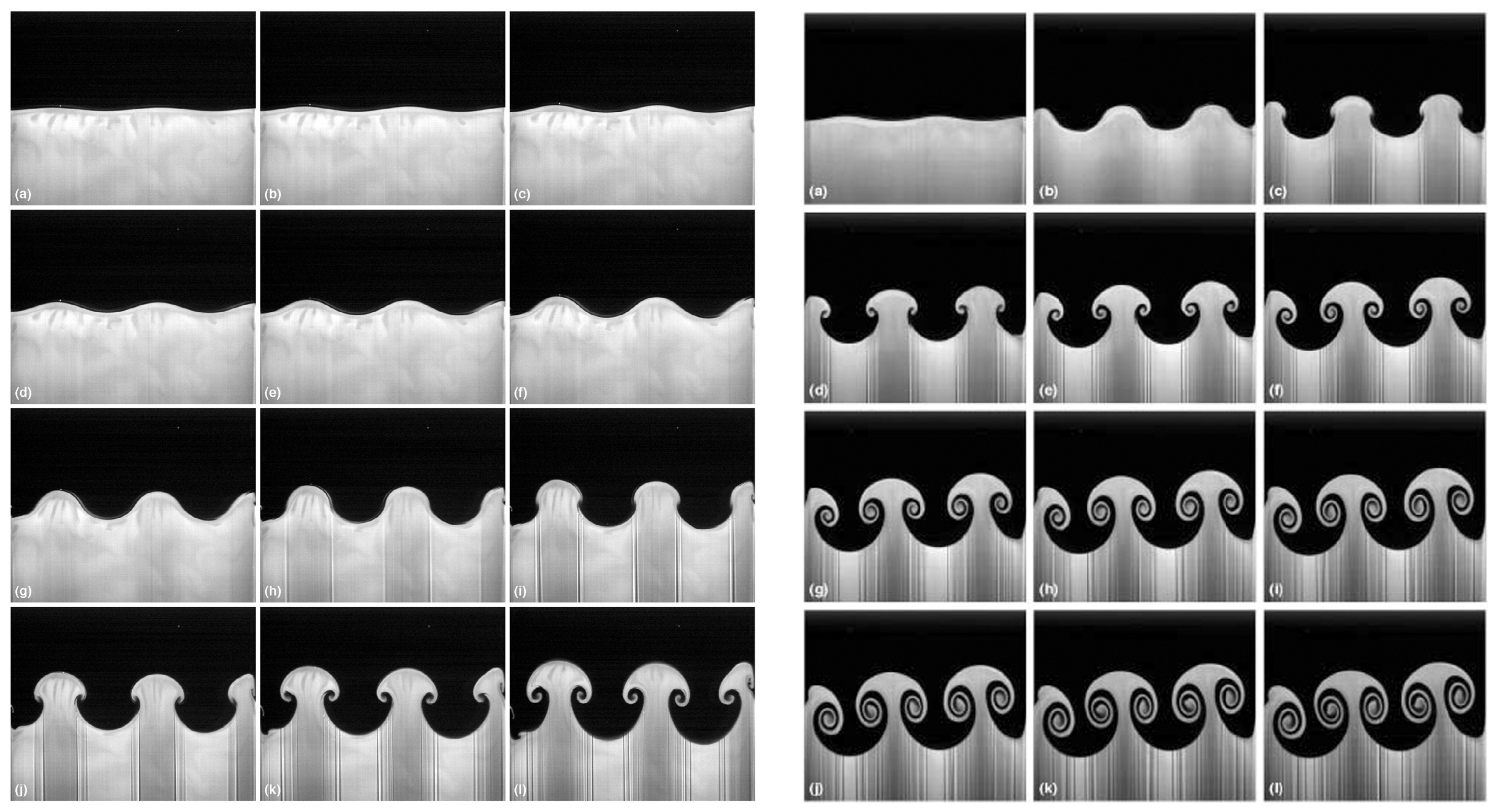
Figure 1. Difference between RTI and RMI in a sled experimental setup. (left) RTI, the time increment between each subsequent image is 33 ms. Reprinted from [62], with the permission of AIP Publishing. (right) RMI, the first image is at time before the shock is delivered, the time increment between each other subsequent image is about 83.5 ms (66 ms between the last two ones). Source [63], reproduced with permission.
Photonics 10 00061 g001
Figure 2. Proton energy layers for hydrogen target: (a) at 190 fs (b) at 230 fs from the beginning of laser–target interaction. The initial position of the target is between 0 μ m and 25 μ m (denoted by the black line). Republished with permission of IOP Publishing, Ltd., from [23], permission conveyed through Copyright Clearance Center, Inc.
Photonics 10 00061 g002
Figure 3. VBL visualization of different proton populations using the hydrogen target: (a) at time frame 67, (b) at time frame 110. The dots represent the simulated protons (only protons that exceed 300 MeV at the end of the simulations are included); the vertical height and color denote their energy using the white–red–blue scale. Laser pulse intensity is represented by the gray scale, electron density by the turquoise scale, and both values are also visualized using the vertical height. The interactive VBL application of the full time evolution is accessible online [84].
Photonics 10 00061 g003
Figure 4. Maximal proton energy and ion spectra from hydrogen target. (a) Temporal evolution of maximum energies of protons accelerated by the RPA and TNSA mechanisms for various laser intensities. (b) Proton energy spectra for linearly and circularly polarized laser beams in 2D and 3D simulations at 260 fs from the beginning of the laser pulse interaction. Target thickness is reduced to 15 μ m and pulse duration to 200 fs. Peak intensity I = 1.5 × 10 22   W / cm 2 . Republished with permission of IOP Publishing, Ltd., from [23], permission conveyed through Copyright Clearance Center, Inc.
Photonics 10 00061 g004
Figure 5. Structured targets and generation of proton bunch, source of the left part (ac) [76]. Initial configuration of deuterium layer (blue) and proton layer (orange) in the cases: (a) double–layer target with the modulation on the interface, (b) single–layer target with the modulation on the front surface, (c) without the modulation. (d) Visualization of case (a) during the laser–target interaction. Coloring: electric field (gray), density of deuterium (blue) and hydrogen (orange). Colors saturated with maximum value set to the initial density. Values are also represented by the vertical height. The distinguished high density proton bunch enfolded by the laser pulse is developed. Source of (d): [94].
Photonics 10 00061 g005
Figure 6. Properties of the ion beam. (a) Time evolution of the tail of the proton energy spectra in the HL case, (b) proton energy spectra of the HL case at time t = 47 T, with highlighted FWHM section used for (c) angular distribution, (d) proton energy spectra (corresponding deuteron energy spectra in inset) for various targets (see details in the text) at time t = 47 T. Reprinted from [41], with permission from Elsevier.
Photonics 10 00061 g006
Figure 7. Spatial density distributions at time t = 47 T. The proton density is represented by the vertical height, and proton energy is represented by the blue to yellow scale. The simulated cases are: (a) HL, (b) LH, (c) HL–WO, (d) L2 (see parameters of all the targets in the text). Reprinted from [41], with permission from Elsevier.
Photonics 10 00061 g007
Figure 8. Short-wavelength instability. (a) Spatial distributions in the HL-FF (with full-front laser pulse) case at time t = 14 T. Blue and red scales represent deuterium and proton densities, with maximum value set to the initial density. Full density is indicated by the vertical height. (b) Proton and deuteron energy spectra for HL (steep-front, interface corrugation), HL-FF (full-front, interface corrugation), and L2-SM (steep-front, surface corrugation) cases at time t = 47 T. Reprinted from [41], with permission from Elsevier.
Photonics 10 00061 g008
Figure 9. Plasma shutter. (a) The distribution of the laser intensity in the horizontal slice of the laser pulse from 3D simulation with the plasma shutter when the maximum intensity value is reached, source [78]. (b) The 1D profile (at y = 0 and z = 0 ) of dimensionless amplitude of the electric field in the y-direction ( a 0 y ) after the laser pulse propagates through the plasma shutter in the 3D simulation. Comparison of the transmitted laser pulse (W/1xSh) with the original one (W/O-Sh). Steep front is generated, its envelope is approximated using the equation y = 140 · sin ( π · x / 9.2 ) . Source [79]. Figures reprinted under the terms of the Creative Commons Attribution 4.0.
Photonics 10 00061 g009
Figure 10. Application of the plasma shutter with a silver target: VBL visualization of our simulation of 1 PW laser (electric field: red color) interacting with the plasma shutter (blue: electron density) and the silver target (green: ion density). Laser pulse is shaped by the plasma shutter (resulting in the aperture) and accelerates ions from the silver target. A high energy ion beam with low divergence is generated. Data used for this visualization come from [79]. The interactive VBL application of the full time evolution is accesible online [112].
Photonics 10 00061 g010
Figure 11. Properties of silver ions from the 3D simulations with the plasma shutter (W/1xSh) and without (W/O-sh) for linear (LP) and circular (CP) polarization. (a) Energy spectra at the end of the simulation ( t = 70 T ), (b) time evolution of the maximal energy. Angular distributions of ions with energy over 55 MeV per nucleon in the x-z plane (c) and x-y plane (d). Source: [79]. Figures reprinted under the terms of the Creative Commons Attribution 4.0.
Photonics 10 00061 g011
Table 1. The main laser–target simulation parameters. In order: Intensity I, polarization, wavelength λ , width of Gaussian space profile at FWHM, temporal shape-duration for sin 2 ( t ) and FWHM for Gaussian, target material, thickness, and electron density n e in the corresponding critical density n c .
SectionI [ W / cm 2 ]Pol. λ [ μ m]Width [ μ m]t-ShapeTargetThickness n e [ n c ]
3.1-2D 3 × 10 22 p1.15 sin 2 ( t ) 320 fsH25 μ m 56
3.1-3D 1.5 × 10 22 p1.15 sin 2 ( t ) 200 fsH15 μ m 56
3.1-VR 3 × 10 22 p1.15 sin 2 ( t ) 200 fsH15 μ m 56
3.2-2D 1.37 × 10 23 s1.010Gauss 26.7 fs 2 H-H(1 + 1) μ m 48
3.3-3D 1 × 10 22 p1.03 sin 2 ( t ) 64 fsShutter Si 3 N 4 20 nm835
Target Ag20 nm2100
Disclaimer/Publisher’s Note: The statements, opinions and data contained in all publications are solely those of the individual author(s) and contributor(s) and not of MDPI and/or the editor(s). MDPI and/or the editor(s) disclaim responsibility for any injury to people or property resulting from any ideas, methods, instructions or products referred to in the content.