Abstract
The optical feedback tolerance (OFT) of a distributed Bragg reflector (DBR) laser was investigated experimentally. The static and modulation performance of the DBR laser under optical feedback was examined by evaluating its relative intensity noise (RIN) and bit error rate (BER). It is shown that the OFT of the DBR laser is closely related to its peak wavelength detuning relative to the Bragg wavelength. A high tolerance to optical feedback was demonstrated, both in the continuous wave (CW) and the direct modulation (DM) states, when the DBR laser was red-detuned relative to the Bragg wavelength. The excess RIN induced by optical feedback was well suppressed to a level of −140 dB/Hz at a feedback level of −9 dB in the CW state. In a 10 Gbps direct modulation state, bit error rates (BER) below 1 × 10⁻⁹ and 3 × 10⁻⁷ were obtained under a feedback level of −15 dB and −9 dB, respectively, for the case of back-to-back transmission. After 20 km fiber transmission, the BER still maintained below 1 × 10⁻⁷ under a feedback level of −15 dB, with a power penalty of less than 1 dB.
1. Introduction
In pace with the development of access network and photonic integration circuit (PIC), semiconductor lasers are playing a growing important role for their low-cost and volume-production characteristics. Due to the nonlinear dynamics of semiconductor lasers, approximately −40 dB (0.01%) of the reflected light injected back into the cavity will start to destabilize the device [1]. Many phenomena will occur under feedback, including the increase in relative intensity noise (RIN), degradation of side mode suppression ratio, period oscillation, coherent collapse, etc. For cost-sensitive applications such as the access network, an optical isolator has to be co-packaged with the laser chip to prevent impairment from the optical feedback, leading to an increased cost of the transceivers. For PICs, the lack of on-chip isolation solutions will also raise a concern for the stability of the PIC comprised of lasers and other integrated components, where multiple reflections are inevitable. Therefore, the motivation to develop feedback-tolerant lasers is increasingly strong in both practical applications and theoretical research. Many schemes have been proposed to increase the stability of the lasers, which includes partially corrugated waveguide laser [2], quantum dot lasers [3], distributed feedback (DFB)+R lasers [4], two-κ distributed Bragg reflector (DBR) lasers [5], distributed reflector (DR) laser [5,6], etc. These solutions have shown their effectiveness in resisting optical feedback. Among them, the DBR laser is a very promising candidate for colorless optical network units (ONU) in XG(S)-PON and NG-PON2 [7,8], due to its wavelength tunability and direct modulation capability [5,9]. A reflection tolerance of −7 dB has been demonstrated for a DBR laser under static continuous wave (CW) condition [5]. However, reports on its dynamic resistance to optical feedback under direct modulation (DM) condition are still lacking in the literature. In the case of DM, the alternation of laser amplitude and the transient behavior of the laser are new sets of parameters to be considered when external optical feedback is introduced [10]. Therefore, additional research is needed.
In this paper, we investigated the static CW and dynamic DM performance of a 1.3-μm DBR laser under optical feedback. The relationship between wavelength detuning and feedback tolerance is examined. The research shows that when the DBR laser is red detuned from the Bragg wavelength, a considerable enhancement in optical feedback tolerance can be obtained. Stable CW operation with an optical feedback level of up to −9 dB has been demonstrated for the red-detuned DBR laser. While for the case of direct modulation at 10 Gbps, a back-to-back (BtB) bit error rate (BER) of 1 × 10⁻⁹ and 3 × 10⁻⁷ has been obtained under a feedback level of −15 dB and −9 dB, respectively. After 20 km fiber transmission, the BER still maintains below 1 × 10⁻⁷ under a feedback level of −15 dB. The power penalty induced by optical feedback is 0.61 dB and 0.75 dB, respectively, for the case of BtB and 20 km fiber transmission under a feedback level of −15 dB.
2. Device Structure and Experimental Setup
The DBR laser was composed of a 180-μm-long gain section, a 100-μm-long phase section, and a 280-μm-long DBR section, separated by isolation regions of 20 μm, as shown in Figure 1a. The AlGaInAs/InP material system was chosen for the gain section for its better carrier confinement and the higher characteristic temperature. The InGaAsP bulk structure was chosen for the passive sections (the phase and DBR sections) for its low absorption loss. The integration of the above two was realized by a butt-joint process. The structure was grown by a three-step metalorganic chemical vapor deposition (MOCVD). In the first-step growth, 9 pairs of strained multiple-quantum-wells (MQWs) were sandwiched between 100-nm-thick separate-confinement heterojunction (SCH) on an n-type InP substrate. After that, the region designed as the passive sections was removed by wet etching to prepare for the butt-joint process. In the second-step growth, a 400-nm-thick core layer was grown to fill the passive sections. After that, the 25-nm-deep Bragg grating pitch was defined by e-beam lithography on part of the core layer. In the final third-step growth, a 2.2-μm-thick InP cladding and InGaAs contact layer were grown on the whole wafer. A 2-μm-wide double trench was fabricated by wet etching. The p-electrode and n-electrode were both made by magnetron sputtering. The laser chip was cleaved and mounted on a high-frequency heat sink for testing.
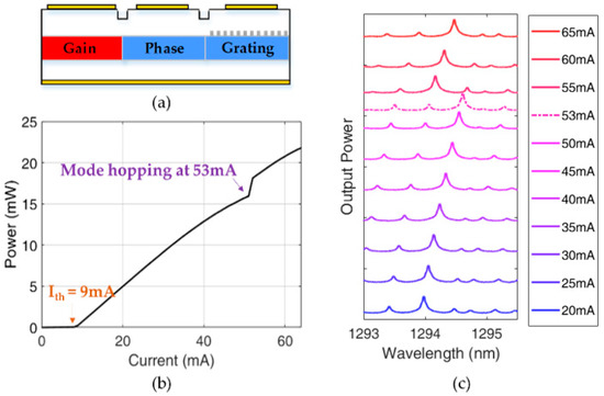
Figure 1.
(a) Schematic diagram of the three-section DBR laser; (b) the light current characteristics at room temperature; (c) optical spectrum measured from 20 mA to 65 mA.
The output power and spectrum of the DBR laser were measured at room temperature (25 °C), as shown in Figure 1b,c. The DBR laser had a threshold current of about 9 mA and a slope efficiency of 0.37 W/A, with output power over 20 mW at a pump current of 60 mA. The light current curve shows a kink at 53 mA due to mode hopping. The optical spectrum plotted in Figure 1c records the whole mode hopping process in preparation for investigating the OFT of the DBR laser. As shown in Figure 1c, the lasing wavelength redshifted continuously with the increase of gain current until the mode-hopping point at 53 mA, where a sudden blueshift occurred. The state before and after mode-hopping respectively correspond to a lasing wavelength on the red and blue flank of the Bragg reflection spectrum. Data are representative of similar results obtained from independent tests performed on dozens of lasers in the same batch, except that the mode hopping points are randomly distributed in the whole range.
Figure 2 shows the schematic measurement setup for the OFT evaluation. The optical feedback is achieved by using a circulator and a variable attenuator. The light emitted from the laser is coupled into the circulator through a tapered fiber and then reinjected back into the laser cavity after a variable attenuator, a 3 dB coupler, and a polarization controller. By adjusting the variable attenuator, the feedback level can be controlled. The overall length of the feedback path is about 7 m, and the maximum feedback strength can reach −9 dB with the roundtrip coupling loss of the tapered fiber as low as −6 dB. All the experiment data are recorded under the worst RIN and transmission performance by controlling the feedback polarization. During the static test, the injection current is provided by a direct current (DC) source. During the modulation test, nonreturn-zero (NRZ) signal generated by a pulse pattern generator (PPG) is applied to the laser through a bias tee. The eye diagram is tested by the sampling oscilloscope, and the BER is tested by the BER Tester after the optical signal is received by a commercial SFP+ transceiver.
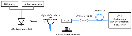
Figure 2.
Illustration of the experimental setup. VOA: Variable Optical Attenuator; SMF: Single Mode Fiber; OSA: Optical Spectrum Analyzer.
3. Results
The OFT of the DBR laser was investigated by examining its RIN and BER performance under certain feedback levels. RIN is a well-known monitor of a free-running laser under feedback. The feedback level resulting in a sharp increase in RIN is denoted as the critical feedback value [11], a widely used quantitative indicator of OFT, beyond which the laser will be destabilized. The influence of the feedback on the directly modulated lasers can be also characterized by evaluating the signal-to-noise ratio (SNR), BER, and power penalty. Note that excess RIN due to optical feedback is the main reason for the increased power penalty during optical fiber transmission.
3.1. Static Performance under Feedback
3.1.1. RIN Spectrum
Three bias current points were chosen to analyze the typical noise characteristics of the DBR laser under feedback, which were 25 mA for low damping region, 50 mA for the red-detuned region before mode hopping, and 55 mA for the blue-detuned region after mode hopping, respectively. The detuning between the lasing wavelength and the center wavelength of the grating spectrum was controlled by adjusting the gain section current rather than the passive section current, since the shot noise and filter noise introduced by the current injected into the passive section are too significant to influence the accurate analysis of the RIN.
In Figure 3a–c, each graph records two spectrums at different bias points, corresponding to the original noise under no feedback and the increased noise under critical feedback. When the laser was biased at 25 mA with no feedback, the overall RIN value was around −143 dB/Hz, except for the peak of −133.1 dB/Hz at 7.1 GHz, the relaxation oscillation frequency. As −20 dB feedback was introduced, the overall RIN value was rapidly improved to over −130 dB/Hz, at least 10 dB worse on average. Three peaks can be roughly identified, which were −97.43 dB/Hz at 6.7 GHz, −107.01 dB/Hz at 13.5 GHz, and −114.70 dB/Hz at 19.9 GHz. When the bias current increased to 50 mA, in the absence of optical feedback, the RIN spectrum became flat due to the increased damping of the oscillation frequency. Note that, at this bias current, the laser should be working in the red-detuned region relative to the Bragg reflection peak. Under a maximum feedback level of −9 dB, the RIN remained below −140 dB/Hz in the whole measurement range of 20 GHz except for the very low-frequency range. Increasing the current to 55 mA, corresponding to a new blue-detuned region after the mode-hopping point, the RIN kept almost unchanged in the absence of optical feedback. However, when −14 dB optical feedback was introduced, the RIN underwent an overall increase to above −135 dB/Hz. The phenomena revealed that DBR lasers are more stable in the red-detuned region than in the blue-detuned region.
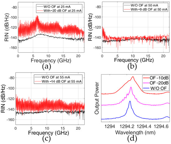
Figure 3.
The RIN spectrum measured under no feedback and feedback at (a) 25 mA; (b) 50 mA; (c) 55 mA; (d) the optical spectrum under feedback at 25 mA.
Figure 3d demonstrated the optical spectrum under feedback at 25 mA. The three lines in the figure correspond to the cases of no feedback, −20 dB, and −10 dB feedback. It can be seen that the spectrum appeared small burrs under critical feedback. As the feedback level continued to increase, the spectrum showed a completely broadened state, indicating coherent collapse. This phenomenon suggested that feedback-induced noise will cause spectral deterioration, which is detrimental to the application.
3.1.2. Critical Feedback Value
To analyze the effect of wavelength detuning on OFT more thoroughly, the critical feedback value was measured, as shown in Figure 4. Figure 4a shows the relationship between the wavelength detuning and critical feedback value. In the low bias current region of (10 mA~40 mA), the laser was sensitive to optical feedback, showing a low critical feedback value. In this region, the wavelength of the laser should locate within the center of the DBR reflection spectrum, where its tolerance to feedback can be roughly explained using the theory described in [11]. While in the higher current region of (40 mA~50 mA), where red detuning of the lasing wavelength occurred, the laser was not easily disturbed, and the RIN remained very stable. Next in the current region of (53 mA~60 mA) following mode hopping, the lasing wavelength was blue-detuned, the laser became sensitive to feedback and a drop in the critical feedback value can be observed. Usually, lasers with high output power and high damping also tend to be more tolerant to optical feedback [11]. To isolate the contribution of the wavelength detuning, we investigated another DBR laser (Laser 2) with a lower mode hopping current in the same batch, so that the influence of high output power and high damping rate can be minimized. The results are shown in Figure 4b. The mode hopping point of this laser was 27 mA, with other characteristics similar to those of the former (Laser 1). For this laser, the red-detuned region at low pump current is located at about several milliamperes below 27 mA. It can be observed that in the red-detuned region before the mode hopping the critical feedback value was significantly enhanced from −18 dB to over −9 dB more dramatically than in Laser 1. In this region, both the output power and the damping rate were not high enough to play a major role in suppressing the feedback noise. Then, after the mode hopping, the critical feedback value suddenly dropped to −19 dB at the beginning of the blue-detuned region, even lower than that of the 10-mA pump. At a higher current, both lasers quickly entered a chaotic state when the feedback was beyond the critical feedback value. The performance of the two lasers showed an identical trend when the lasing wavelength swept across the Bragg peak, which suggests evidently that wavelength detuning has a significant influence on OFT.
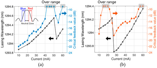
Figure 4.
The lasing wavelength and critical feedback value at a different bias current of (a) Laser 1 with the mode hoping point at 53 mA, and the inset depicts the detuning relative to the Bragg reflection spectrum. (b) Laser 2 with the mode hoping point at 27 mA. Gray shading indicates the critical feedback value exceeded the measurement upper limit of −9 dB.
The remarkably high feedback tolerance at the red-detuned region of the DBR laser can be a very promising property for isolator-free operation. One can also note that, although the OFT in the blue-detuned region is not as good as that of the red-detuned region, it is still better than that of most DFB lasers [12].
3.2. Modulation Performance under Feedback
3.2.1. Signal-to-Noise Ratio of the Eye Diagram
To investigate the influence of the wavelength detuning on the modulation performance of the DBR laser under direct modulation, the SNR of the modulated signal was first examined. The two DBR lasers mentioned above were directly modulated by using a 10.3125 Gbps pseudo-random bit sequence (PRBS) with a pattern length of 215 − 1 under different feedback levels. The extinction ratio (ER) was set to a relatively small value of 2 dB to demonstrate the clear dependence of the SNR on the wavelength detuning. Higher ERs also showed a similar trend, but not as significant as the low ER case. The feedback level was set to a moderate level of −15 dB. The SNR of the eye diagram was measured by a sampling oscilloscope. The variation of SNR versus bias current is shown in Figure 5.
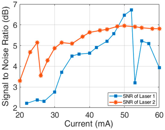
Figure 5.
The SNR of the two lasers under −15 dB feedback at a fixed ER of 2 dB.
When the bias current was below 30 mA, all SNRs were poor. As the current increased, the overall SNR improved. For Laser 1, the improvement before the mode hopping point was monotonous. The higher the current was, the higher the SNR would be. After the mode hopping, the SNR dropped suddenly by 3 dB. This is consistent with the prediction from the CW critical feedback value. For Laser 2, the SNR increased to 5 dB before the mode hopping point of 27 mA, followed by a sudden drop at the blue-detuned region. Then with the increase in the pump current, the SNR increased back from 3.5 dB to 6 dB, which was also consistent with the static performance shown in Figure 4b.
The result shows that the wavelength detuning has a similar influence on the eye diagram SNR as that of the CW case under optical feedback. The OFT performance of a directly modulated DBR laser should depend on the wavelength detuning of the laser and can be roughly inferred from the critical feedback value measured at the CW condition.
3.2.2. BER Property and Eye Diagram
After evaluating the SNR, the BER and eye diagram were examined for the cases of back-to-back (BtB) and 20 km standard mode single-mode fiber (SMF) transmission. Laser 1 was biased at the red-detuned region of 50 mA for the BER test. The modulation signal was still 10.3125 Gbps PRBS NRZ. According to the requirement of the XG(S)-PON application, the ER should be set to at least 6 dB. The influence of ER on modulation and feedback was first evaluated from the eye diagram using two values, 6 dB and 10 dB, respectively. As seen in Figure 6, the eye diagram for the ERs of 6 dB and 10 dB are both clear without feedback. The distinctions are that the 10 dB case has an overshoot, and its logical zero bit is much closer to the zero level than that of the 6 dB case. Under a strong feedback level of −12 dB, the SNRs were 7.32 dB and 8.16 dB, respectively, for 6 dB ER and 10 dB ER cases. In the following BER evaluation, a high ER of 10 dB was selected for the transmission test.
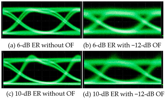
Figure 6.
Eye diagrams of the directly modulated DBR Laser 1 for a fixed bias current of 50 mA with an ER of: (a) 6 dB without feedback; (b) 6 dB with −12 dB feedback; (c) 10 dB without feedback; (d) 10 dB with −12 dB feedback.
The BER curve and eye diagram of the laser for the cases of BtB and 20 km transmission are shown, respectively, in Figure 7 and Figure 8. Without feedback, the minimum receiver sensitivities were −18.06 dBm. In the BtB configuration, an error-free operation under −15 dB feedback has been successfully demonstrated with a power penalty of <3 dB at 1 × 10⁻⁹. The BER degradation was relatively minor before that feedback level. When the feedback level increased to −12 dB, a BER floor appeared at 1 × 10⁻⁸. The BER floor continued to rise with the increase in the feedback level. Under the maximum system feedback level of −9 dB, the BER still met the FEC limit of 1 × 10⁻³ required by access networks. With the increase of the feedback level, the eye diagrams deteriorated gradually but were still wide open. For the case of 20 km transmission, an error-free transmission under −20 dB optical feedback was reached with a power penalty of around 5 dB at 1 × 10⁻⁹. A BER floor of 1 × 10⁻⁷ was observed at −15 dB feedback. The laser could still meet the FEC limit at −12 dB feedback but failed at a higher feedback level (data not shown). In the worst case, there was a large amount of noise at the intersection of the rising and falling edges, as well as the center of the unit intervals, which led to the failure to reach the FEC limit.
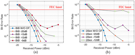
Figure 7.
The BER curves under different feedback levels (a) in BtB configuration and (b) in 20 km transmission configuration.
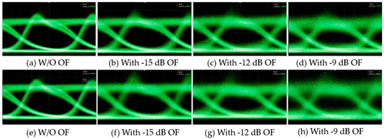
Figure 8.
Eye diagrams corresponding to the BER results; upper row (a–d) is obtained in the BtB configuration under W/O, −15, −12, and −9 dB feedback level; lower row (e–h) is obtained in the 20 km transmission configuration under W/O, −15, −12, and −9 dB optical feedback.
3.2.3. Power Penalty
The power penalty at the FEC limit of 1 × 10⁻³ was summarized in Table 1. For the BtB configuration, the dependence of power penalty on the feedback levels is positively correlated. For the 20 km transmission, a positive correlation still exists. At the early stage of −30 dB and −20 dB, the penalty is slightly less than that in BtB due to the influence of the eye diagram distortion and the fiber dispersion. The feedback-induced power penalty remains below 1 dB until −12 dB in BtB and −15 dB, respectively, for the case of BtB and 20 km transmission, which satisfied the requirements of ONU transmitter in XG(S)-PON.

Table 1.
Power penalty at FEC limit of 1 × 10⁻³ for the case of BtB and 20 km fiber transmission.
4. Discussion
We finally discuss why wavelength detuning affects feedback tolerance. According to the latest theoretical analysis [13,14], we infer that the detuned loading effect should be the main reason for the high feedback tolerance of a red-detuned DBR laser, but possibly not all. It is well known that the critical feedback value has a simple and useful analytical expression with some approximations and assumptions from Lang-Kobayashi (L-K) model [11]:
where is the reflectivity of the active region facet, is the roundtrip cavity time, is the damping rate, and is the effective linewidth enhancement factor. This formula is in good agreement with the experiments in the long external cavity and weak feedback situation. For DBR lasers, except for , three of the four parameters are closely related to wavelength detuning via the detuned loading effect [13,14]. For a pair of neighboring red-detuned region and blue-detuned region, we ignore the small current difference and assume the same settings except for the detuning. The first parameter is enhanced in both red and blue-detuned regions because the effective roundtrip cavity length is enhanced [14], which is beneficial to feedback tolerance. The next two parameters and show different trends. In the red-detuned region, is enhanced and is reduced, so the whole critical feedback value is improved. In the blue-detuned region, all the trends are opposite, is declined. The detuned loading effect on and is the main reason for the high feedback tolerance of a red-detuned DBR laser.
However, when we conduct a rough quantitative estimation, there will be a discrepancy between the experimental and theoretical results. The damping rate of Laser 2 was measured by a Vector Network Analyzer. The maximum occurs at 65 mA with a value of 45 GHz. When we take the largest of 45 GHz, ideally the smallest of 0, longest cavity length of 600-μm for and around 30% into the formula, the estimated critical feedback value is −15 dB, which is far lower than over −9 dB obtained in the static test. Therefore, we can recognize that the detuning loading effect is not the only reason for high feedback tolerance, which is identical to the analysis in [13].
5. Conclusions
In summary, we studied the OFT of a three-section DBR laser in both static and modulated states. The results confirmed the significant influence of wavelength detuning from the Bragg wavelength on OFT. When the DBR laser is working in the red-detuned region, the OFT can be greatly enhanced, which is favorable for both continuous and direct-modulation applications. The excess RIN induced by optical feedback was remarkedly suppressed in the CW state under the feedback level of −9 dB. In the DM state, the red-detuned DBR laser also demonstrated superior stability against feedback. An error-free operation at a feedback level of −15 dB was realized in the BtB configuration. For 20 km fiber transmission, the eye diagram was still wide open at a feedback level of −12 dB, and the power penalty at FEC limit is lower than 1 dB under −15 dB feedback. The DBR laser working in the red-detuned region has demonstrated its outstanding stability against feedback, which makes it a promising candidate as a colorless ONU transmitter for XG(S)-PON and NG-PON2.
Author Contributions
Conceptualization, D.L. and Q.Y.; methodology, Q.Y.; validation, Q.Y.; formal analysis, Q.Y.; investigation, Q.Y.; writing—original draft preparation, Q.Y.; writing—review and editing, D.L. and Y.H.; visualization, Q.Y.; supervision, D.L. and L.Z.; project administration, D.L. and L.Z.; and funding acquisition, D.L. and D.Z. All authors have read and agreed to the published version of the manuscript.
Funding
This research was funded by the Beijing Municipal Natural Science Foundation, grant number 4212056, and National Natural Science Foundation of China (NSFC), grant number 61975197.
Institutional Review Board Statement
Not applicable.
Informed Consent Statement
Not applicable.
Data Availability Statement
Not applicable.
Conflicts of Interest
The authors declare no conflict of interest.
References
- Tkach, R.W.; Chraplyvy, A. Regimes of Feedback Effects in 1.5 μm Distributed Feedback Laser. IEEE J. Light. Technol. 1986, 4, 1655–1661. [Google Scholar] [CrossRef]
- Huang, Y.; Yamada, H. External optical feedback resistant characteristics in partially-corrugated-waveguide laser diodes. In Proceedings of the Optical Fiber Communication Conference, Jose, CA, USA, 25 February–1 March 1996. [Google Scholar]
- He, Y.; Zhang, Z.; Lv, Z.; Yang, T.; Lu, D.; Zhao, L. 10-Gbps 20-km Feedback-Resistant Transmission Using Directly Modulated Quantum-Dot Lasers. IEEE Photonics Technol. Lett. 2020, 32, 1353–1356. [Google Scholar] [CrossRef]
- Matsui, Y.; Schatz, R.; Che, D.; Khan, F.; Kwakernaak, M.; Sudo, T. Isolator-free > 67-GHz bandwidth DFB+R laser with suppressed chirp. In Proceedings of the Optical Fiber Communication Conference, San Diego, CA, USA, 8–12 March 2020. [Google Scholar]
- Matsui, Y.; Schatz, R.; Che, D.; Khan, F.; Kwakernaak, M.; Sudo, T. Low-chirp isolator-free 65-GHz-bandwidth directly Modulated Lasers. Nat. Photonics 2021, 15, 59–64. [Google Scholar] [CrossRef]
- Lee, S.H.; Tajima, N.; Shindo, T.; Takahashi, D.; Nishiyama, N.; Arai, S. High optical feedback-tolerance of distributed reflector lasers with wire-like active regions for isolator-free operation. IEEE Photonics Technol. Lett. 2009, 21, 1529–1531. [Google Scholar] [CrossRef]
- Chen, M.; Shindo, T.; Kanazawa, S.; Nada, M.; Nakanishi, Y.; Nakamura, H. Enhancement of Optical-Feedback Tolerance of SOA-Integrated EML (AXEL) by Introducing DBR-Type Laser. IEEE Photonics Technol. Lett. 2020, 34, 502–505. [Google Scholar] [CrossRef]
- Nesset, D. NG-PON2 technology and standards. IEEE J. Light. Technol. 2015, 33, 1136–1143. [Google Scholar] [CrossRef]
- G.9807.1; Transmission Systems and Media, Digital Systems and Networks, 10-Gigabit-Capable Symmetric Passive Optical Network (XGS-PON). ITU-T: Geneva, Switzerland, 2020.
- Ahmed, M.; Yamada, M.; Mahmoud, S.W.Z. Analysis of semiconductor laser dynamics under gigabit rate modulation. IEEE J. Appl. Phys. 2007, 101, 033119. [Google Scholar] [CrossRef]
- Helms, J.; Petermann, K. A Simple Analytic Expression for the Stable Operation Range of Laser Diodes with Optical Feedback. IEEE J. Quantum Electron. 1990, 26, 833–836. [Google Scholar] [CrossRef]
- Grillot, F.; Thedrez, B.; Gauthier-Lafaye, O.; Martineau, M.F.; Voiriot, V.; Lafragette, J.L.; Gentner, J.L.; Silvestre, L. Coherence-Collapse Threshold of 1.3-um Semiconductor DFB Lasers. IEEE Photonics Technol. Lett. 2003, 15, 9–11. [Google Scholar] [CrossRef]
- Tronciu, V.; Werner, N.; Wenzel, H.; Wunsche, J.H. Feedback Sensitivity of Detuned DBR Semiconductor Lasers. IEEE J. Quantum Electron. 2021, 57, 2100107. [Google Scholar] [CrossRef]
- Morthier, G. Feedback Sensitivity of DBR-Type Laser Diodes. IEEE Photonics J. 2021, 13, 1500205. [Google Scholar] [CrossRef]


Disclaimer/Publisher’s Note: The statements, opinions and data contained in all publications are solely those of the individual author(s) and contributor(s) and not of MDPI and/or the editor(s). MDPI and/or the editor(s) disclaim responsibility for any injury to people or property resulting from any ideas, methods, instructions or products referred to in the content. |
© 2022 by the authors. Licensee MDPI, Basel, Switzerland. This article is an open access article distributed under the terms and conditions of the Creative Commons Attribution (CC BY) license (https://creativecommons.org/licenses/by/4.0/).