Simulation and Optimization of the Separation of Methanol-Dimethyl Carbonate Azeotrope by Extractive Dividing Wall Column

Abstract
:1. Introduction
2. Method
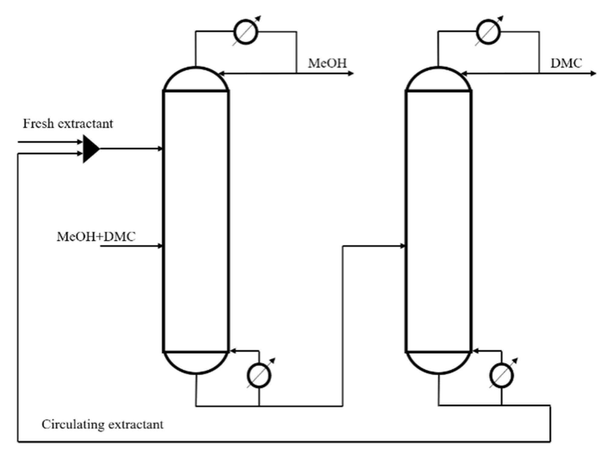
2.1. Design Method
2.2. Simulation Conditions
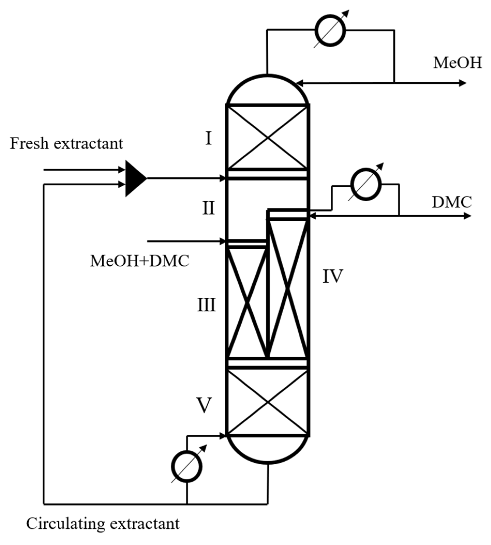
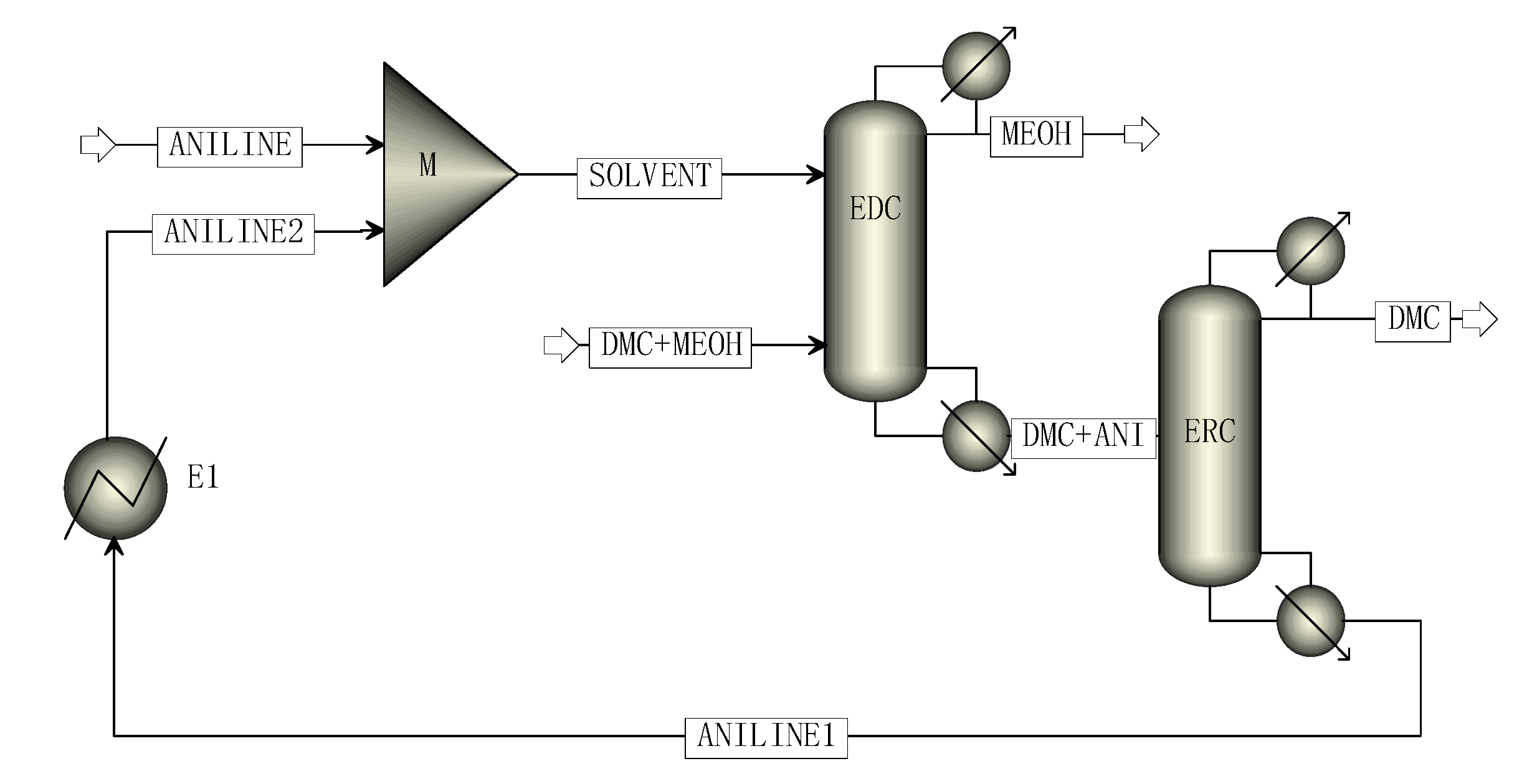
2.3. Process Modeling
3. Results and Discussion
3.1. Univariate Analysis
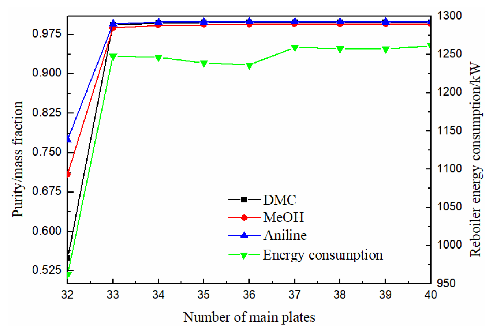
3.1.1. Effect of Number of Main Plates
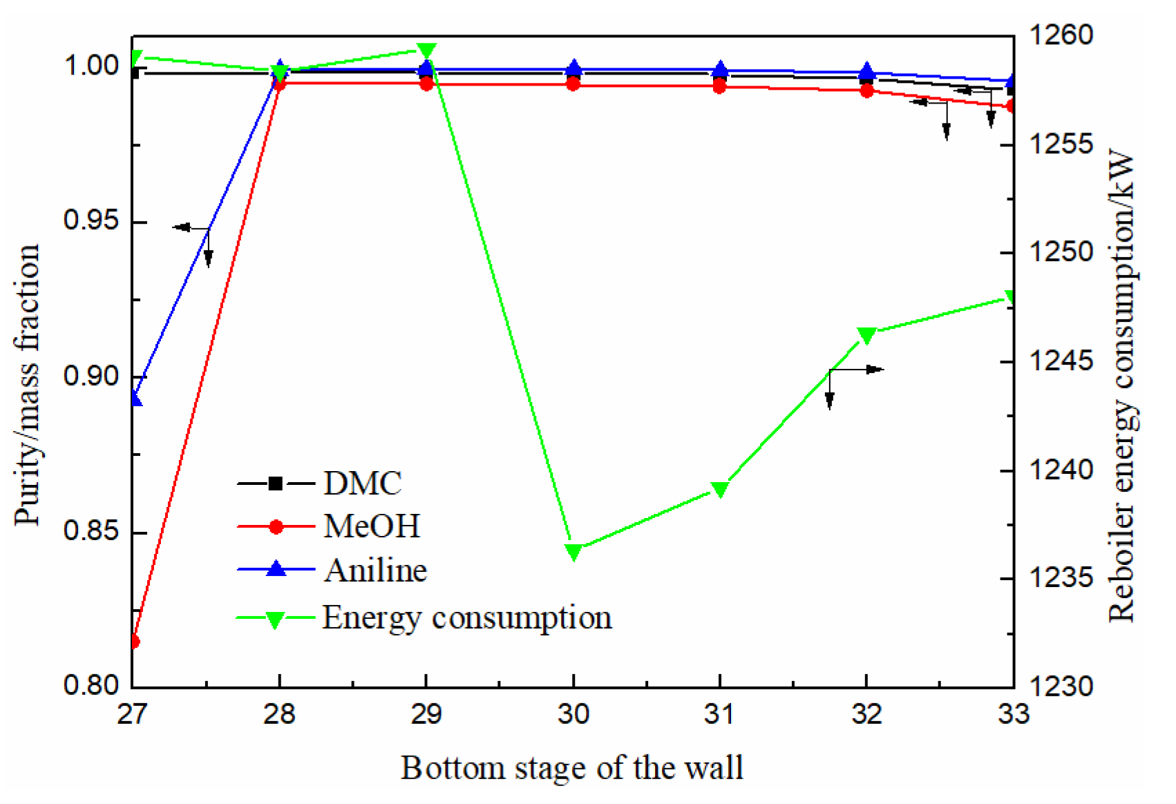
3.1.2. Effect of Bottom Stage of the Partition
3.1.3. Effect of Raw Material Feed Stage
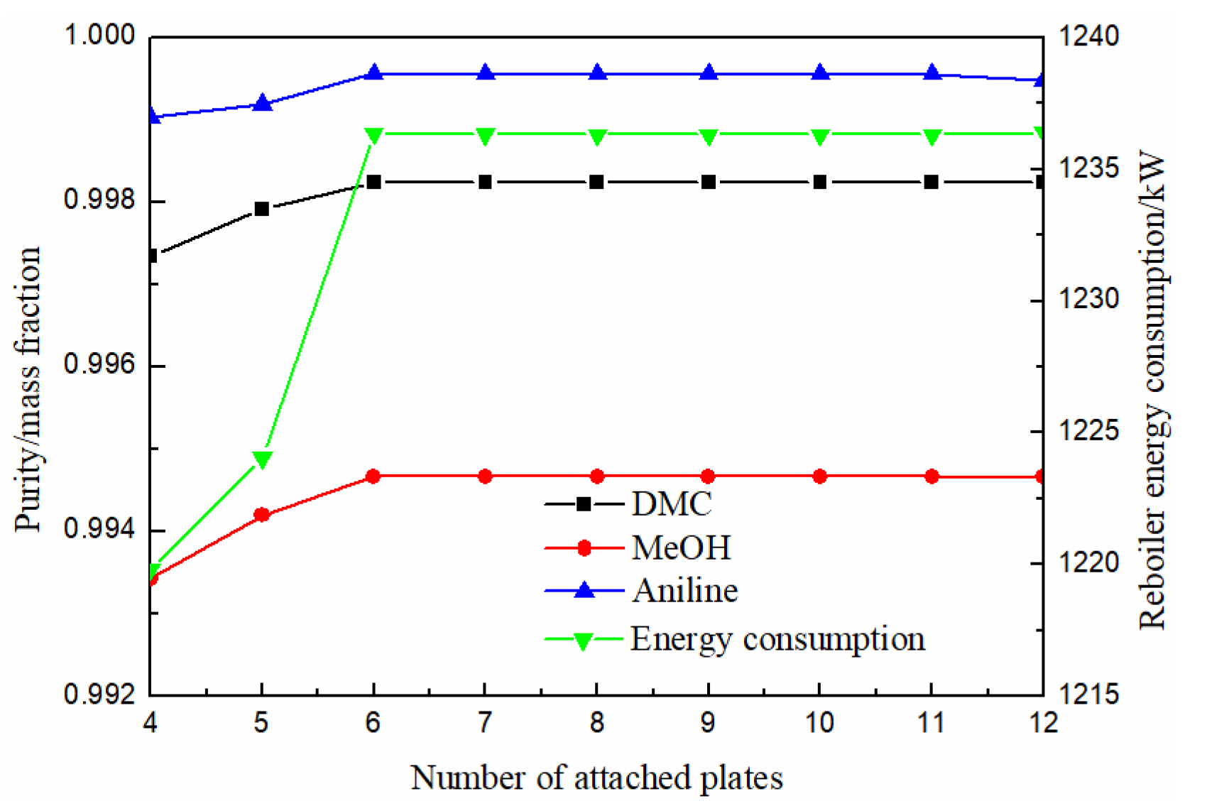
3.1.4. Effect of Number of Attached Plates
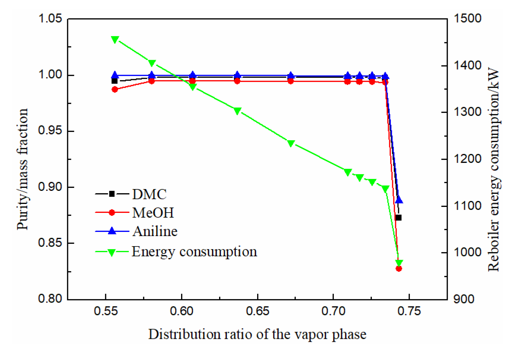
3.1.5. Effect of Distribution Ratio of the Vapor Phase
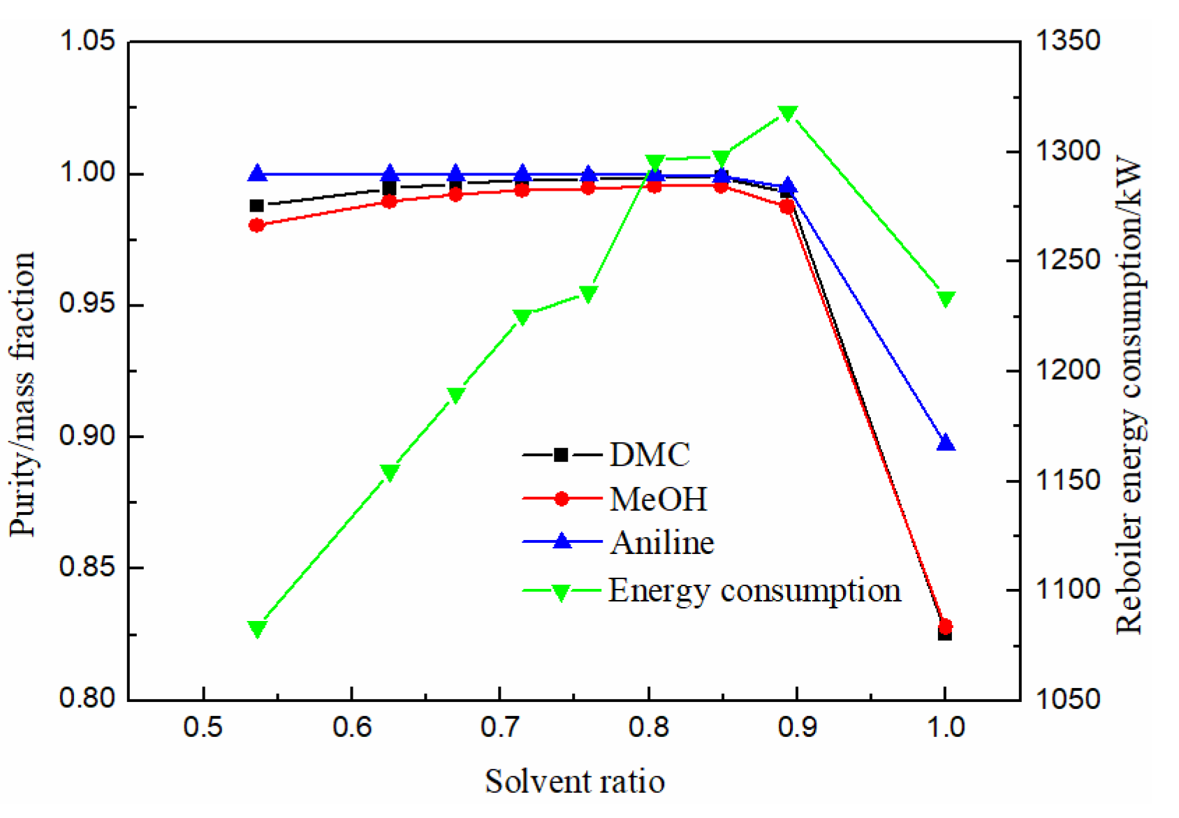
3.1.6. Effect of Solvent Ratio
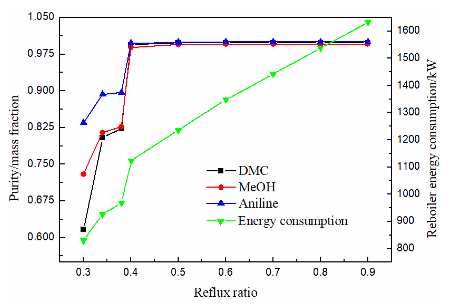
3.1.7. Effect of Reflux Ratio
3.2. Profile Analysis
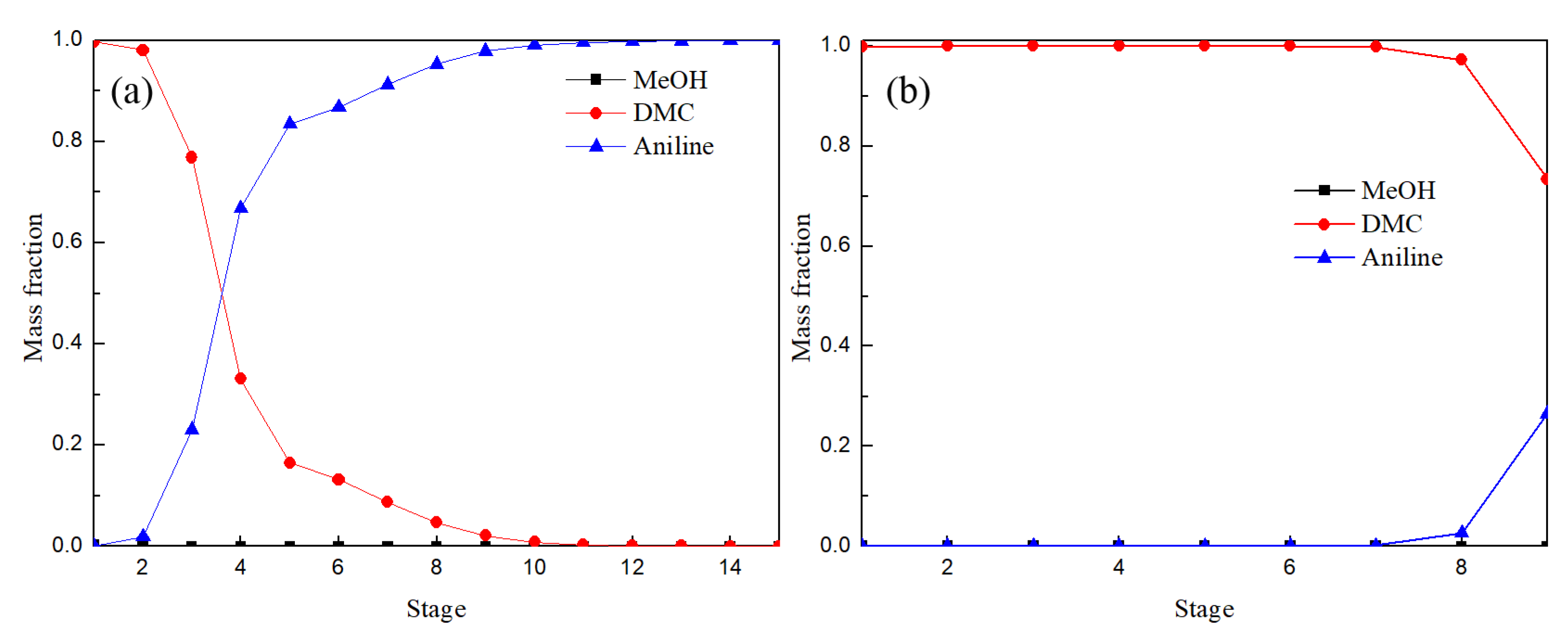
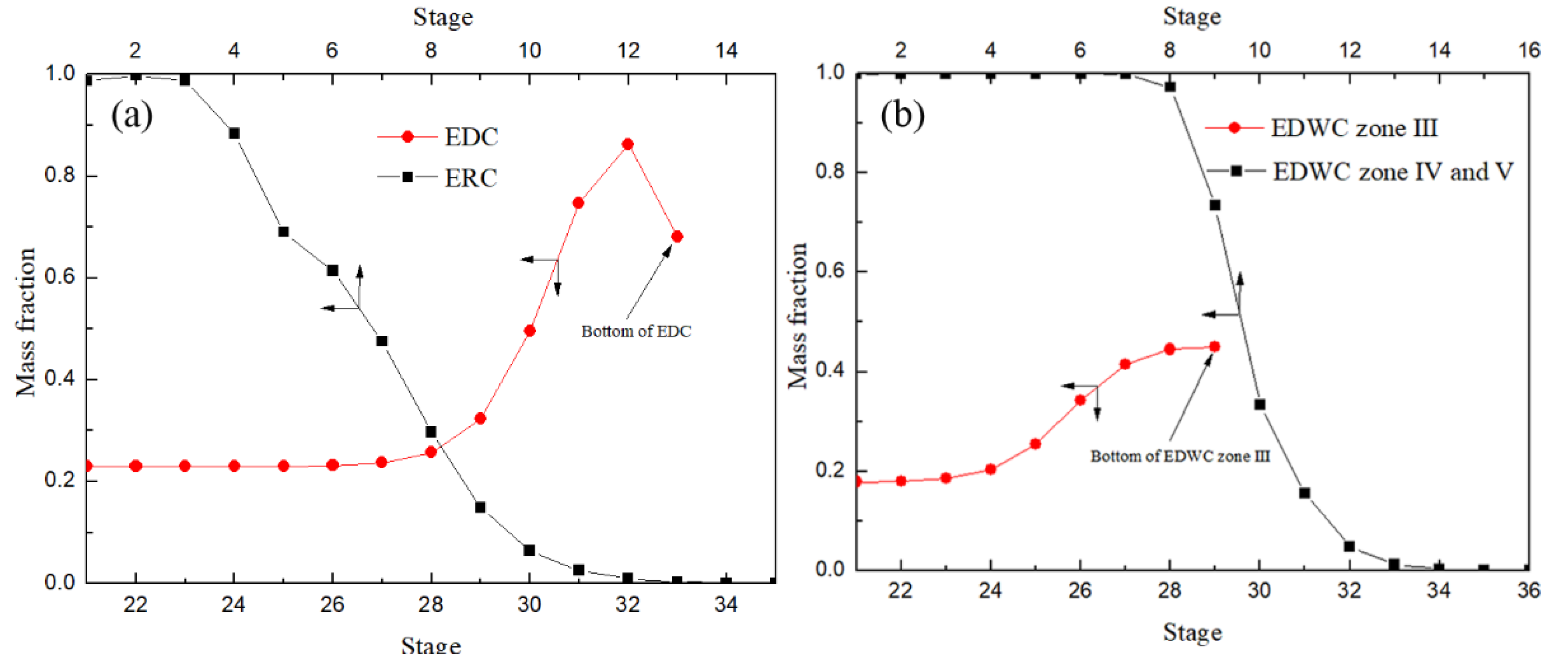
3.2.1. Composition Distribution Analysis
3.2.2. Temperature Distribution Analysis
3.3. Comparison and Analysis of Simulation Results
4. Conclusions
Author Contributions
Funding
Institutional Review Board Statement
Informed Consent Statement
Data Availability Statement
Acknowledgments
Conflicts of Interest
Nomenclature
| CEP | Conventional extractive process |
| DMC | Dimethyl carbonate |
| EDWC | Extractive dividing wall column |
| EDC | Extractive distillation column |
| ERC | Extraction agent recovery column |
| MeOH | Methanol |
References
- Li, X.; Ma, Q.; Wei, C.; Cai, W.; Chen, H.; Xing, R.; Song, P. Green and Simple Extraction of Arsenic Species from Rice Flour Using a Novel Ultrasound-Assisted Enzymatic Hydrolysis Method. Separations 2022, 9, 105. [Google Scholar] [CrossRef]
- Hsu, K.-Y.; Hsiao, Y.-C.; Chien, I.-L. Design and Control of Dimethyl CarbonateMethanol Separation via Extractive Distillation in the Dimethyl Carbonate Reactive-Distillation Process. Ind. Eng. Chem. Res. 2009, 49, 735–749. [Google Scholar] [CrossRef]
- Fang, Y.-J.; Xiao, W.-D. Experimental and modeling studies on a homogeneous reactive distillation system for dimethyl carbonate synthesis by transesterification. Sep. Purif. Technol. 2004, 34, 255–263. [Google Scholar] [CrossRef]
- Guo, C.; Wang, F.; Xing, J.; Cui, P. Thermodynamic and economic comparison of extractive distillation sequences for separating methanol/dimethyl carbonate/water azeotropic mixtures. Sep. Purif. Technol. 2022, 282, 120150–120160. [Google Scholar] [CrossRef]
- Yu, B.Y.; Chen, M.K.; Chien, I.L. Assessment on CO2 Utilization through Rigorous Simulation: Converting CO2 to Dimethyl Carbonate. Ind. Eng. Chem. Res. 2017, 57, 639–652. [Google Scholar] [CrossRef]
- Matsuda, H.; Takahara, H.; Fujino, S.; Constantinescu, D.; Kurihara, K.; Tochigi, K.; Ochi, K.; Gmehling, J. Selection of entrainers for the separation of the binary azeotropic system methanol+dimethyl carbonate by extractive distillation. Fluid Phase Equilibria 2011, 310, 166–181. [Google Scholar] [CrossRef]
- Glover, C.J.; Phillips, J.A.; Marchand, E.A.; Hiibel, S.R. Modeling and Life Cycle Assessment of a Membrane Bioreactor—Membrane Distillation Wastewater Treatment System for Potable Reuse. Separations 2022, 9, 151. [Google Scholar] [CrossRef]
- El Batouti, M.; Alharby, N.F.; Elewa, M.M. Review of New Approaches for Fouling Mitigation in Membrane Separation Processes in Water Treatment Applications. Separations 2021, 9, 1. [Google Scholar] [CrossRef]
- Wei, H.M.; Wang, F.; Zhang, J.L.; Liao, B.; Zhao, N.; Xiao, F.K.; Wei, W.; Sun, Y.H. Design and Control of Dimethyl Carbonate–Methanol Separation via Pressure-Swing Distillation. Ind. Eng. Chem. Res. 2013, 52, 11463–11478. [Google Scholar] [CrossRef]
- Zhang, Q.R.; Peng, J.Y.; Zhang, K. Design and control of dimethyl carbonate and methanol separation via heat-integrated pressure swing distillation. Chem. Eng. 2017, 45, 60–65. [Google Scholar]
- Lingna, L.; Tao, F.; Yurong, J. Simulation and economic evaluation of process for synthesizing dimethyl carbonate. Nat. Gas Chem. Ind. 2015, 40, 69–73. [Google Scholar]
- Dejanović, I.; Matijašević, L.; Olujić, Ž. Dividing wall column—A breakthrough towards sustainable distilling. Chem. Eng. Processing Process Intensif. 2010, 49, 559–580. [Google Scholar] [CrossRef]
- Guidat, R.; Vizza, A.; Jiang, Y. Advanced-Flow Reactor Technologies Makes Continuous-Flow Industrial Production Real. Spec. Chem. Mag. 2015, 35, 30–32. [Google Scholar]
- Lestak, F.; Collins, C. Advanced distillation saves energy & capital. Chem. Eng. 1997, 104, 72–76. [Google Scholar]
- Sander, S.; Flisch, C.; Geissler, E.; Schoenmakers, H.; Ryll, O.; Hasse, H. Methyl Acetate Hydrolysis in a Reactive Divided Wall Column. Chem. Eng. Res. Des. 2007, 85, 149–154. [Google Scholar] [CrossRef] [Green Version]
- Ibarra-Sánchez, J.D.J.; Segovia-Hernández, J.G. Reducing energy consumption and CO2 emissions in extractive distillation. Chem. Eng. Res. Des. 2010, 88, 135–145. [Google Scholar] [CrossRef]
- Wang, S.-J.; Lee, C.-J.; Jang, S.-S.; Shieh, S.-S. Plant-wide design and control of acetic acid dehydration system via heterogeneous azeotropic distillation and divided wall distillation. J. Process Control 2008, 18, 45–60. [Google Scholar] [CrossRef]
- Shiyao, L.; Pingli, L.; Yajing, Z.; Yingdong, L.; Heying, C.; Enxia, S. Advances on applications of dividing wall column in extractive distillation technology. Mod. Chem. Ind. 2019, 39, 65–69. [Google Scholar]
- Xingwu, C.; Lanyi, S.; Qingsong, L.; Jinchuan, X. Simulation of Dividing-wall Extractive Distillation Column for the Separation of Methanol and Acetone. Sci. Online 2009, 1–5. [Google Scholar]
- Ke, P.; Benyuan, H.; Kefeng, W. Simulation study on separation of pentane mixture by extractive distillation dividing wall column. Mod. Chem. Ind. 2020, 40, 221–2255. [Google Scholar]
- Chengshuai, L.; Deqing, S.; Bowen, L.; Huilong, S. Simulation and optimization of separation process of tert-butanol ethanol and water mixture by extractive separation. Petrochem. Technol. Appl. 2020, 38, 108–112. [Google Scholar]
- Yang, S. Computer simulation and energy saving on separation of vinyl acetate-methanol by dividing wall extractive distillation column. Mod. Chem. Ind. 2020, 40, 250–253. [Google Scholar]
- Chengshuai, L.; Deqing, S.; Bowen, L.; Huilong, S. Simulation and optimization of acetonitrile-water separation with three equivalent models of extractive distillation dividing wall column. Nat. Gas Chem. Ind. 2021, 46, 94–99. [Google Scholar]


| Component | Boiling Point/°C | Mole Composition |
|---|---|---|
| Methanol | 64.8 | |
| DMC | 90.1 | |
| Aniline | 184.4 | |
| Methanol–DMC | 63.7 | (0.86, 0.14) |
| Parameters | CEP | EDWC | ||
|---|---|---|---|---|
| EDC | ERC | Main Plate | Attached Plate | |
| Plate number | 33 | 15 | 36 | 9 |
| Feed position of solvent | 5 | - | 5 | - |
| Feed position of raw material | 21 | 5 | 21 | 9 |
| Side-line production position | - | - | 30 | - |
| Solvent ratio | 0.76 | - | 0.76 | - |
| Reflux ratio | 0.70 | 1.30 | 0.50 | 1.03 |
| Distribution ratio of the vapor phase | - | 0.67 | ||
| Purity of methanol | 0.9955 | 0.9947 | ||
| Methanol recovery rate | 0.9989 | 0.9991 | ||
| Purity of DMC | 0.9973 | 0.9982 | ||
| DMC recovery rate | 0.9968 | 0.9951 | ||
| Condenser temperature/℃ | 56.9 | 88.88 | 56.90 | 89.01 |
| Condenser duty/kW | −1615.04 | −372.82 | −1425.67 | −326.64 |
| Total duty of condenser/kW | −1987.86 | −1752.31 | ||
| Reboiler temperature/℃ | 148.63 | 183.83 | 183.79 | - |
| Reboiler duty/kW | 966.68 | 506.54 | 1236.32 | - |
| Total duty of reboiler/kW | 1473.22 | 1236.32 | ||
Publisher’s Note: MDPI stays neutral with regard to jurisdictional claims in published maps and institutional affiliations. |
© 2022 by the authors. Licensee MDPI, Basel, Switzerland. This article is an open access article distributed under the terms and conditions of the Creative Commons Attribution (CC BY) license (https://creativecommons.org/licenses/by/4.0/).
Share and Cite
Zheng, M.; Wang, J. Simulation and Optimization of the Separation of Methanol-Dimethyl Carbonate Azeotrope by Extractive Dividing Wall Column. Separations 2022, 9, 189. https://doi.org/10.3390/separations9080189
Zheng M, Wang J. Simulation and Optimization of the Separation of Methanol-Dimethyl Carbonate Azeotrope by Extractive Dividing Wall Column. Separations. 2022; 9(8):189. https://doi.org/10.3390/separations9080189
Chicago/Turabian StyleZheng, Meiqin, and Jiawei Wang. 2022. "Simulation and Optimization of the Separation of Methanol-Dimethyl Carbonate Azeotrope by Extractive Dividing Wall Column" Separations 9, no. 8: 189. https://doi.org/10.3390/separations9080189
APA StyleZheng, M., & Wang, J. (2022). Simulation and Optimization of the Separation of Methanol-Dimethyl Carbonate Azeotrope by Extractive Dividing Wall Column. Separations, 9(8), 189. https://doi.org/10.3390/separations9080189