Article

Simulation of CO2 Capture Process in Flue Gas from Oxy-Fuel Combustion Plant and Effects of Properties of Absorbent

1
College of Biological Chemical Science and Engineering, Jiaxing University, Jiaxing 314041, China
2
ZheJiang Supcon Software Co., Ltd., Hangzhou 310053, China
3
College of Chemical Engineering, Zhejiang University of Technology, Hangzhou 310023, China
4
Energy and Bioproducts Research Institute, Aston University, Birmingham B4 7ET, UK
*
Authors to whom correspondence should be addressed.
Separations 2022, 9(4), 95; https://doi.org/10.3390/separations9040095
Submission received: 21 February 2022 / Revised: 29 March 2022 / Accepted: 3 April 2022 / Published: 11 April 2022
(This article belongs to the Special Issue Advances in CO2 Adsorptive Separation for CO2 Capture)

Abstract

:
Oxy-fuel combustion technology is an effective way to reduce CO2 emissions. An ionic liquid [emim][Tf2N] was used to capture the CO2 in flue gas from oxy-fuel combustion plant. The process of the CO2 capture was simulated using Aspen Plus. The results show that when the liquid–gas ratio is 1.55, the volume fraction of CO2 in the exhaust gas is controlled to about 2%. When the desorption pressure is 0.01 MPa, desorption efficiency is 98.2%. Additionally, based on the designability of ionic liquids, a hypothesis on the physical properties of ionic liquids is proposed to evaluate their influence on the absorption process and heat exchanger design. The process evaluation results show that an ionic liquid having a large density, a large thermal conductivity, and a high heat capacity at constant pressure is advantageous. This paper shows that from capture energy consumption and lean circulation, oxy-fuel combustion is a more economical method. Furthermore, it provides a feasible path for the treatment of CO2 in the waste gas of oxy-fuel combustion. Meanwhile, Aspen simulation helps speed up the application of ionic liquids and oxy-fuel combustion. Process evaluation helps in equipment design and selection.

1. Introduction

The excessive emission of carbon dioxide has become an increasingly serious challenge [1,2]. At the UN Climate Change Conference held in 2018, the UN Intergovernmental Panel on Climate Change released a report saying that humans only have about 12 years to curb global warming. One of the main reasons for global warming is the massive burning of fossil fuels [3]. Although governments have been vigorously developing a variety of clean energies, fossil fuels such as coal are still the primary energy source in the world, especially in China. Therefore, the capture and storage of CO2 has become a high-priority demand.
At present, there are three types of carbon capture technology, i.e., pre-combustion capture, post-combustion capture, and oxy-fuel combustion capture [4,5,6]. Post-combustion capture is a technology that absorbs CO2 from the flue gas which discharges from the power plant. It is the most commonly used method for solving CO2 problems [7]. Pre-combustion capture is also termed fuel decarbonization. Coal gasification is used to obtain CO, CO2, and H2 (syngas). CO is converted to CO2 by a water–gas shift reaction and then separated from the remaining hydrogen-containing gas before the gas turbine burns [8]. Among them, oxy-fuel combustion capture has become a hot spot for scholars because of its unique advantages [9,10]. Oxy-fuel combustion was introduced in 1982 [11]. It first separates O2 from the air. Then, it replaces combustion-supporting air with high-purity oxygen and recycled flue gas to obtain high-concentration CO2 based on existing coal-fired power generation. This technology can also significantly reduce the emission of oxynitride and sulfide [12,13,14]. Foreign scholars have comprehensively explored its mechanisms, status, and applications [11,15,16]. In China, Huazhong University of Science and Technology and North China Electric Power University have carried out extensive research on the topic [17]. Several of the studies indicate that oxy-fuel combustion capture could be more energy- and cost-efficient than the carbon capture technology [13,18,19]. Many fossil fuels, such as coal [20], natural gas [21], and biomass [22], could use oxy-fuel combustion technology. Liu and Niu et al. have also applied this technology to sludge treatment [23].
After increasing the CO2 concentration by oxy-fuel combustion, CO2 capture process is still required. The most widely used method at present is chemical absorption. For example, ALSTOM, ABB Lummus Global Inc, American Electric Power, National Energy Technology Laboratory, and Ohio Coal Development Office evaluated the technical feasibility of oxy-fuel combustion and applied it to an existing 450 MW US bituminous coal-fired power plant. They found that the CO2 recovery of oxy-fuel combustion is higher than air-fired systems when using MEA and MEA/MDEA as absorbents [11]. Fabienne also used MEA to absorb the CO2 escaped from oxy-fuel combustion plants [13]. If outlet gases are H2O and CO2, a multi-stage compression method is applied to obtain a liquid CO2 product. Sung and others have performed this [24,25,26]. However, these absorbents cause problems such as high equipment corrosion and energy consumption [27]. Ionic liquid is an effective solvent to deal with these issues [28].
Ionic liquids (ILs) are salts composed entirely of anions and cations at room temperature. They possess low vapor pressure and good thermal stability, and especially high solubility for CO2 [29]. Ma Tao et al. used [bmim][BF4] and [bmim][PF6] to capture CO2 from model flue gas, which reduced energy consumption by 26.7% and 24.8%, respectively, compared to MEA-based processes. Thus, such an IL-based CO2 capture process is more competitive than traditional MEA-based CO2 capture process [30]. The emergence of functionalized ionic liquids further improves the absorption capacity of CO2. MacFarlane synthesized a variety of bisamino protonated ionic liquids. Among them, DEEDAH formate has the best absorption effect on CO2, with an absorption capacity of 0.47 mol CO2/mol ILs [31]. Chaban further studied the thermodynamic properties of five amino-functionalized ionic liquids (imidazoles, pyridines, morpholines, pyrrolines, and pyrazolines) and compared the absorption effect of CO2 by different amination sites [32].
Oxy-fuel combustion technology is still under investigation. The existing literature is not enough to promote the application of oxy-fuel combustion in industry. In addition, the assessment of the absorption process after oxy-fuel combustion and the discussion of various influencing factors are not sufficient.
In this paper, the CO2 capture process of a 35 MW oxy-fuel combustion device was innovatively designed. The absorbent was ionic liquid [emim][Tf2N]. The simulation of the entire process was performed using Aspen Plus 9.0 software. Based on the designability of ionic liquids, a hypothesis on the physical properties of ionic liquids was proposed, and the effects of ionic liquid properties on the absorption process and heat exchanger design were evaluated, in order to provide ideas for the synthesis of ionic liquids with specific functions. The energy consumption of oxy-fuel combustion capture and post-combustion capture was also compared. The research will provide a feasible method for tail gas purification of oxy-fuel combustion and a new idea for energy saving and emission reduction in the absorption process.

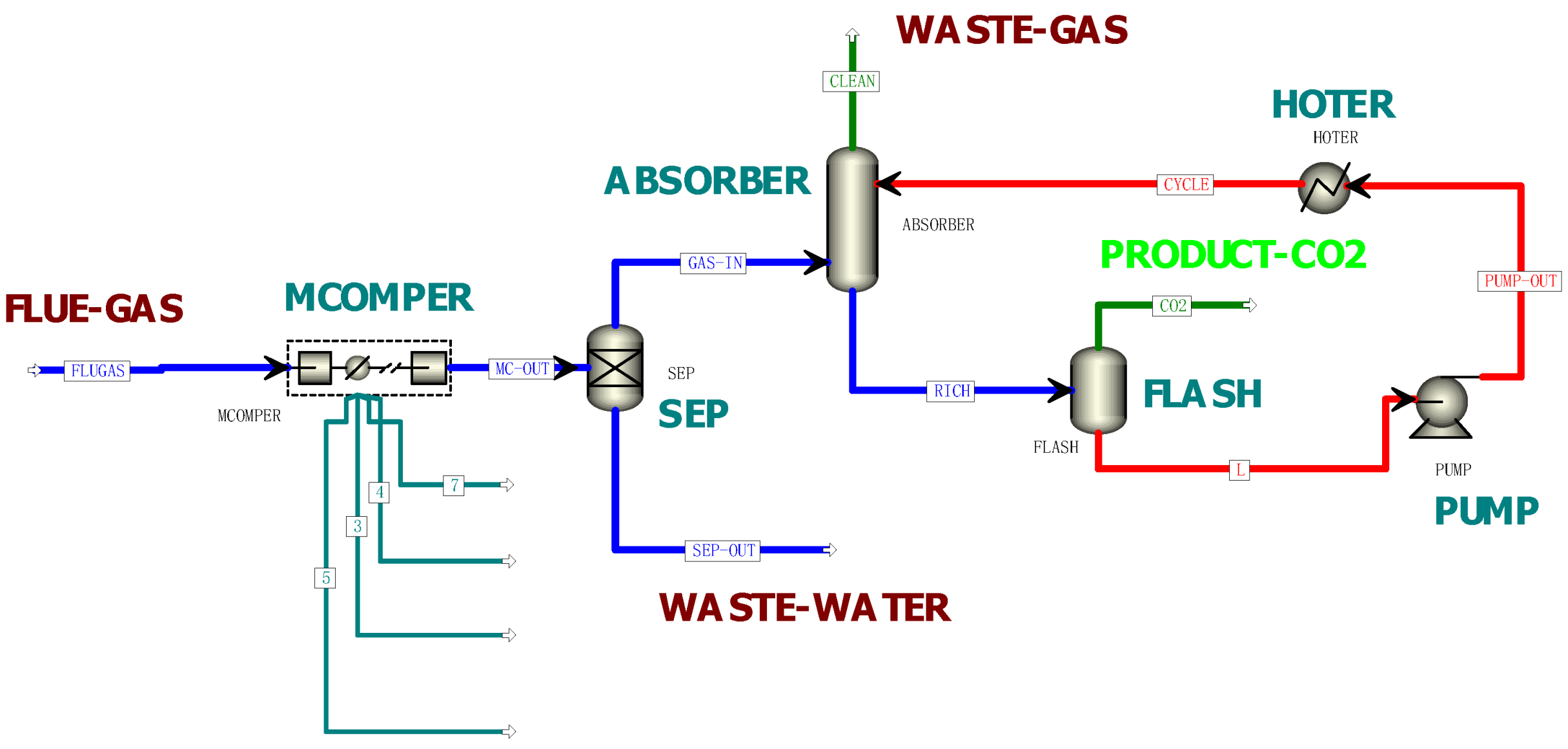
2. Materials and Methods

Chemical process simulation is a common technical method used by chemical engineering technicians to solve chemical process problems. It provides a relatively reliable reference for the simulation and optimization of industrial processes [33]. This section simulates the process of CO2 capture in flue gas from oxy-fuel combustion by [emim][Tf2N]. [emim][Tf2N] is an environmentally friendly solvent. There are no reports of environmental harm. It costs slightly more than some common absorbents, such as MDEA. The parameters of [emim][Tf2N] involve physical parameters, critical parameters, binary interaction parameters, and solubility. These have been calculated in detail in previous work [34]. Table 1 shows various properties, while Table 2 and Table 3 show the results of parameter regression using solubility data at medium and high pressures [35,36]. This simulation provided operating conditions, including temperature, pressure, flow rate, and calculated energy consumption. The effect of physical parameters on carbon capture was also studied.
The flue gas that escaped from the Yingcheng 35 MW oxy-fuel combustion industry demonstration base [1,2] was the simulation object. The temperature of the flue gas after washing was 333 K, the absorption pressure was 0.15 MPa, and the flow rate was 84,000 m3·h−1. The composition of the flue gas is rounded and shown in Table 4.
The process flow diagram of CO2 capture by ionic liquid is shown in Figure 1. It includes the following operating units.
  • A flue gas pretreatment unit:
The flue gas discharged from the oxy-fuel combustion plant is desulfurized and washed, and the temperature of the gas is reduced to 333 K. Next, it is compressed to the absorption operating pressure (7 MPa) by a multi-stage compressor unit (MCOMPER). There is a cooler after each stage of the compressor, where the flue gas is cooled, and the resulting condensate is removed. The flue gas is then dried in a desiccator (SEP) to remove excess water after multi-stage compression.
2.
An absorption unit:
The pretreated gas enters from the bottom of the absorption tower (ABSORBER). Then, it is placed in countercurrent contact with the [emim][Tf2N] stream entering from the top of the tower. The CO2 is gradually absorbed by the ionic liquid. The insoluble gas and a trace amount of CO2 are discharged from the top of the tower.
3.
A solvent desorption unit:
The ionic liquid with a large amount of CO2, also called rich liquid, is withdrawn from the bottom of the absorption tower. It then enters the flash tank (FLASH). By reducing the pressure, CO2 is desorbed from the rich liquid to form the product stream. The resulting ionic liquid after desorbing is called lean liquid, which is passed through a circulating pump (PUMP) and a circulation heater (HOTER). Finally, it returns to the absorption tower for absorption again.
The main equipment includes a compressor (MCOMPER), an absorption tower (ABSORBER), a flash tank (FLASH), a pump (PUMP), and a heat exchanger (HOTER). The parameter settings are shown in Table 5 and the data value of liquid ionic solvent, including the temperature at inlet and outlet of absorber, can be found in Table S1 in the Supporting Information.

3. Results and Discussions

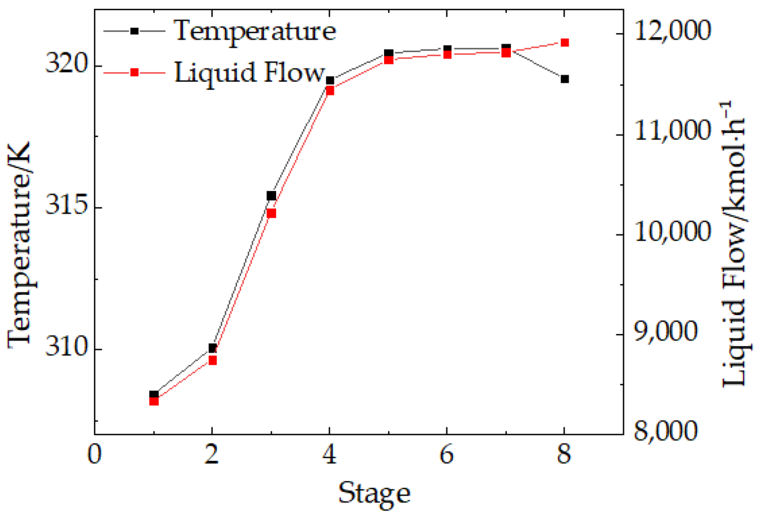
3.1. Simulation Results of Aspen Plus

This paper simulates the absorption process of CO2 in the flue gas from an oxy-fuel combustion by ionic liquid, in light of physical parameters obtained from previous work [30]. When the liquid–gas ratio is 1.55 (molar/molar), 0.45 mole of CO2 is absorbed by 1 mole of ionic liquid (7 MPa, 333 K), and the volume fraction of CO2 in the exhaust gas is controlled to be about 2%. When the desorption pressure is 0.01 MPa, the desorption efficiency is 98.2% and the purity of the obtained CO2 product is as high as 99.9%.
Figure 2 shows the temperature and liquid molar flow distribution in the absorption column. The temperature between the second plate and the fifth plate rises fastest from 310 K to 320 K, because the ionic liquid releases a large amount of heat when CO2 dissolves in it; thus, the temperature curve is steep. After the sixth plate, the absorption gradually balances so the temperature curve becomes smooth. Until the eighth plate, the temperature falls. Due to CO2 dissolved in the liquid, the liquid flow keeps rising. Since the maximum attraction force occurs between the second plate and the sixth plate, this is the best adsorption force. The liquid holding capacity also rises the fastest. Figure 2 shows that it is reasonable to take eight theoretical plates for the simulation.
It can be seen from the simulation results that the ionic liquid has a good absorption effect in absorbing oxygen-enriched combustion flue gas.

3.2. Compare between Post-Combustion Capture and Oxy-Fuel Combustion Capture

Due to the high CO2 concentration in fuel gas, oxy-fuel combustion process is beneficial for the capture process. Table 6 compares post-combustion capture and oxy-fuel combustion capture (both use the same absorbent [emim][Tf2N]). In terms of lean circulation, using oxy-fuel combustion saves 75.59% compared to post-combustion. In terms of energy consumption, using oxy-fuel combustion saves 81.42% of energy consumption compared to post-combustion (the energy consumption of air separation systems is not taken into account). Ionic liquid has low vapor pressure and high solubility of CO2 [29]. In the process of desorption and transportation, it is not easy to volatilize; thus, the solvent loss is small. In addition, the high concentration of CO2 obtained after oxy-fuel combustion increases the absorption-driving force; therefore, the amount of lean liquid circulation is low, and the energy consumption is small.
However, the high-purity oxygen required for oxy-fuel combustion is provided by an air separation system that consumes a lot of energy [37,38]. A conventional cryogenic air separation unit may consume between 10% and 40% of the power output of an oxy-fuel combustion plant [39]. This is not considered in the process simulation; thus, from the perspective of the entire process, it still needs further investigation by calculating the exact cost of energy consumption and solvent circulation.
In this section, oxy-fuel combustion technology and post-combustion capture technology are compared, and the advantages of oxy-fuel combustion technology are explained. A new application was found for ionic liquids.

3.3. Effect of Physical Properties of Ionic Liquid on Absorption Process
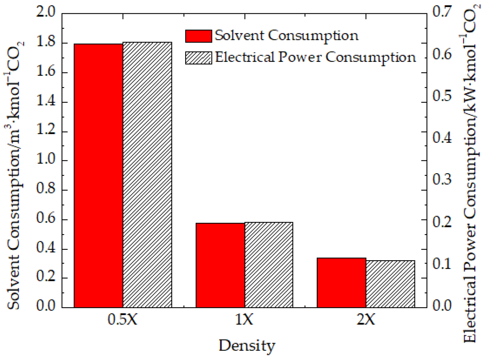
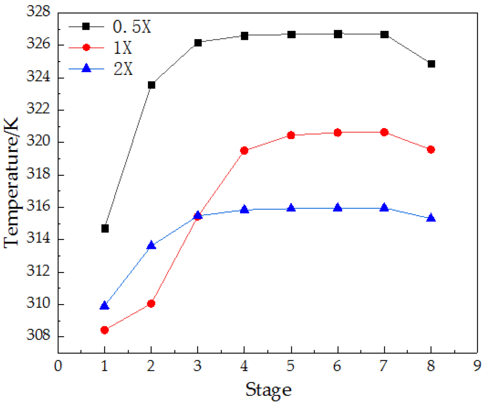
The absorption capacity is mainly affected by the nature of ionic liquids. Scholars from all over the world are looking for ionic liquids with the best performance. They not only conduct research experiments on a series of conventional ionic liquids, but also propose and synthesize functionalized ionic liquids, such as amino-functionalized ionic liquids and proton-type ionic liquids [40,41]. This further improves the solubility of carbon dioxide in ionic liquids. Therefore, the effect of the physical properties of the ionic liquid itself on the absorption process will be discussed in the following part.
Ionic liquids can be designed according to actual needs because of their designability. Therefore, we propose a hypothesis: under the premise that the solubility of CO2 in ionic liquid is the same, the simulation is performed with different physical property parameters (density, heat capacity at constant pressure) of 0.5, 1, and 2 times (marked as 0.5X, 1X, and 2X), respectively. This paper aims to study the effects of properties on the capture process and provide critical information for the screening and design of ionic liquids.

3.3.1. Density

Figure 3 shows the effect of the density of the ionic liquid on the solvent circulation and energy consumption when the unit CO2 is absorbed. It should be noted that the absorption pressure was kept as a constant. Because the energy consumption of the compressor was unchanged under different physical parameters of the ionic liquid, accounting for a large proportion, the energy consumption of the multi-stage compressor unit was excluded for the convenience of calculation. When the solvent density is assumed to be 0.5X, 1X, and 2X, the circulating solvent amount of 1 kmol CO2 is 1.7954 m3/h, 0.5763 m3/h, and 0.3404 m3/h, and the unit energy consumption is 0.6325 kW, 0.203 kW, and 0.112 kW, respectively. If the density is doubled, the solvent circulation is reduced by 67.90% and 40.93%, and the unit energy consumption is reduced by 67.90% and 40.83%, respectively. This is because when mass is constant, the density is inversely proportional to volume. The higher the density, the smaller the volume of liquid per unit mass, and the smaller the required circulation volume. In this way, the power required by pumps is reduced, and the energy consumption is naturally reduced. Given that, the larger the density, the smaller the circulation amount of the solvent and the energy consumption.

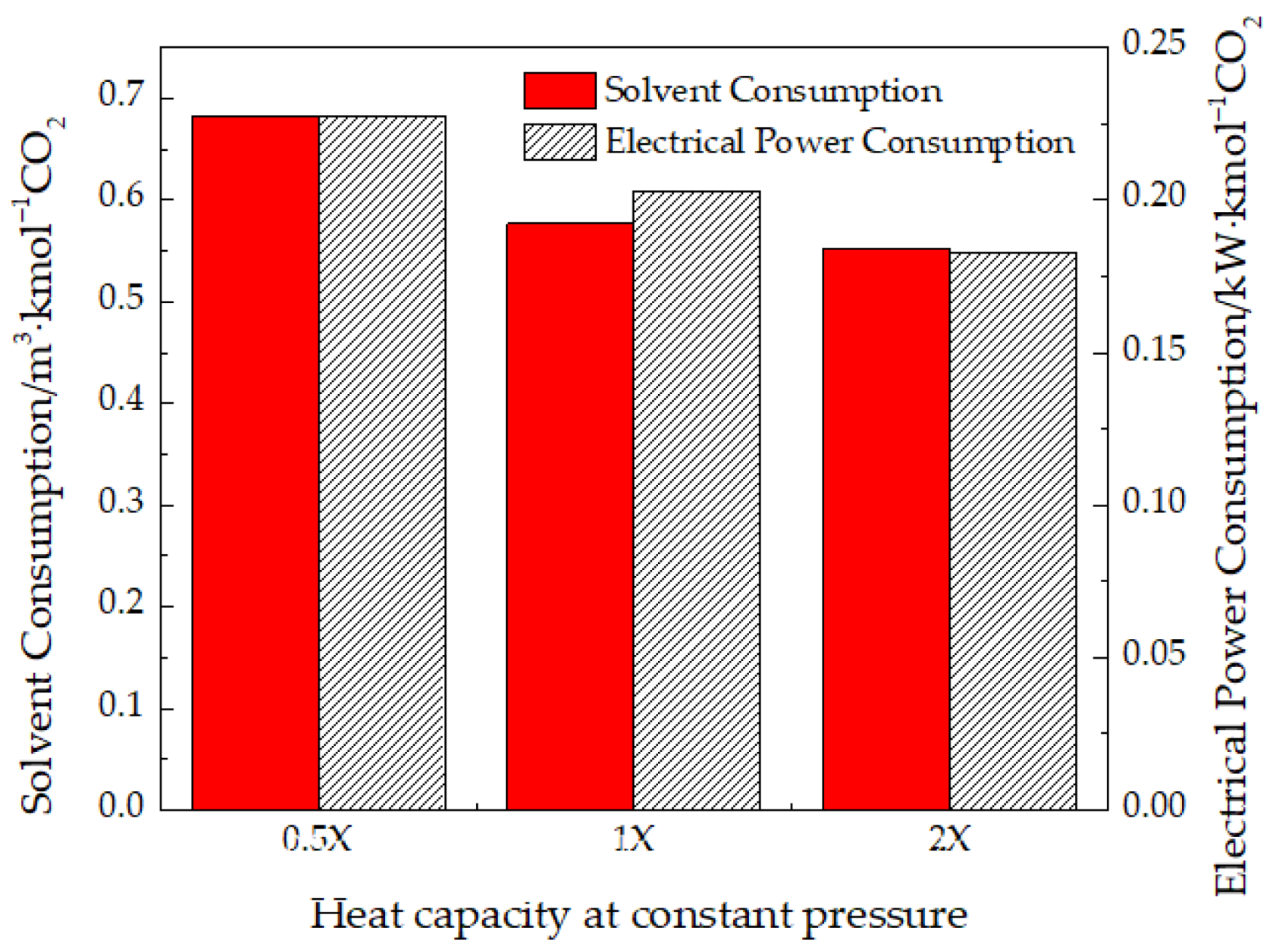
3.3.2. Heat Capacity at Constant Pressure

The greater the heat capacity at constant pressure, the better the absorption effect. When the ionic liquid absorbs CO2, the temperature of the solution in the column rises due to the release of heat. Figure 4 shows the effect of the heat capacity at constant pressure on the temperature distribution in the absorption tower. The higher heat capacity at constant pressure leads to a smoother temperature distribution curve in the absorption tower. When the temperature rises by 1 K, the ionic liquid with a large heat capacity at constant pressure can absorb more heat. Figure 5 further shows that for every two times the heat capacity at constant pressure, the solvent cycle is reduced by 15.66% and 4.11%, and the unit energy consumption is reduced by 10.77% and 10.05%, respectively. During the absorption process, when the amount of heat released by CO2 is constant, the temperature of the ionic liquid with a small heat capacity at constant pressure is expected to rise sharply. The increase in temperature causes an increase in the intermolecular motion of the ionic liquid, inhibiting further dissolution of CO2. It requires more ionic liquid to achieve the same absorption. Therefore, the ionic liquid circulation increases and the energy of capturing unit carbon dioxide increases.

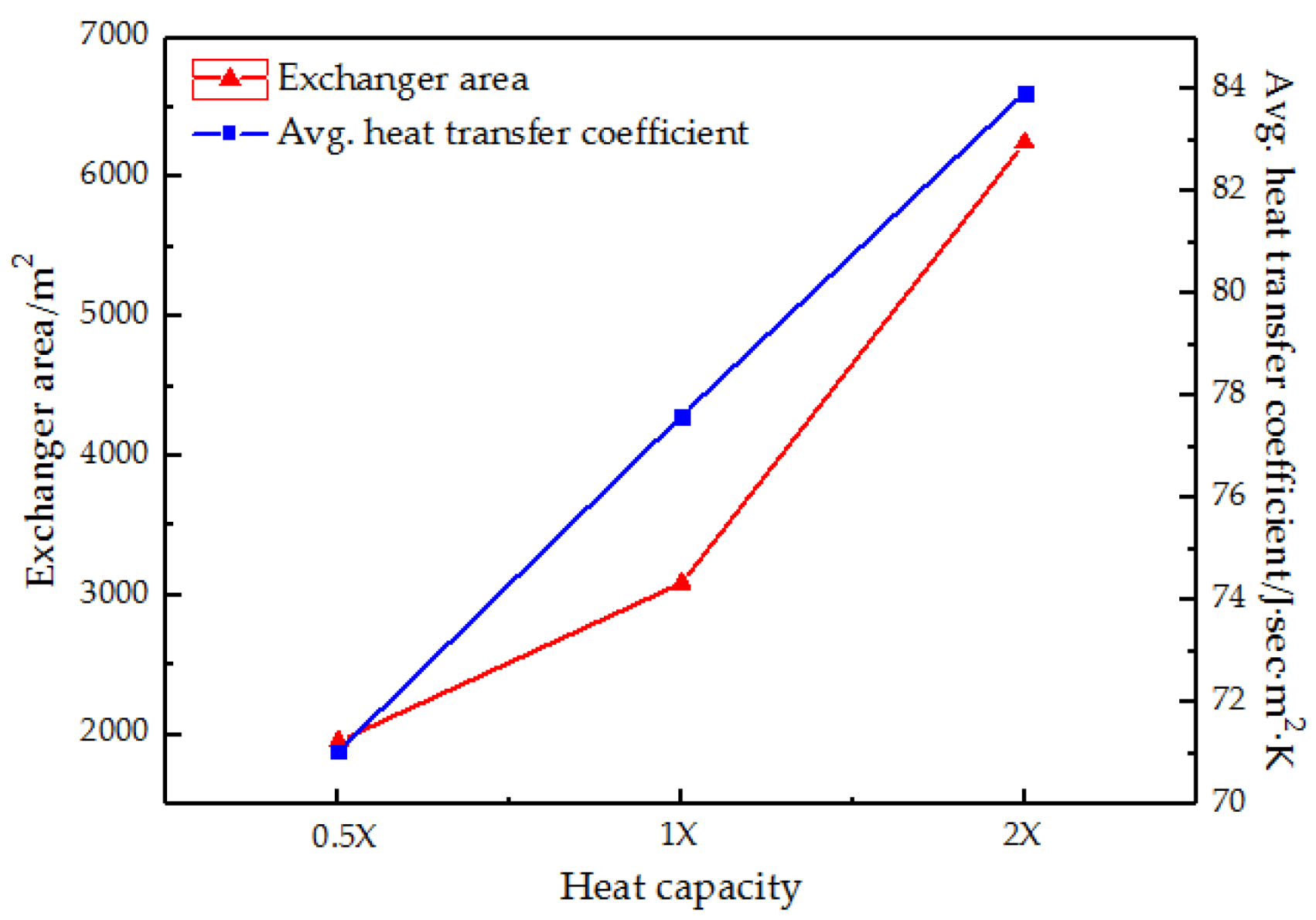
3.4. Influence of Physical Properties of Ionic Liquid on Heat Exchanger Design
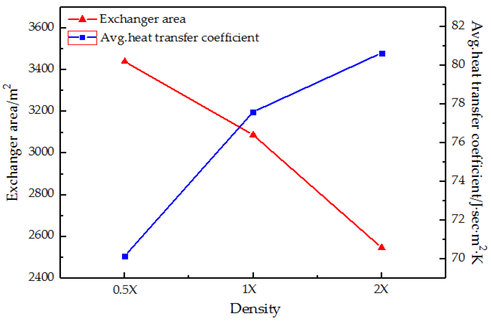
The heat exchanger is essential equipment in industrial production. The physical properties of the ionic liquid have a certain impact on the design and choice of the heat exchanger. Therefore, this section proposes the same hypothesis: under the premise of the same solubility of CO2 in the ionic liquid, the simulation is performed with different physical property parameters (density, heat capacity at constant pressure, and heat transfer coefficient) of 0.5, 1, and 2 times, respectively. This section describes the effects of the physical properties of ionic liquid on heat exchanger design—for example, the density, thermal conductivity, and heat capacity at constant pressure. Furthermore, 5000 mol/h of ionic liquid (some properties are different from [emim][Tf2N], while the rest of the performance is the same) is required from 328 K to 323 K, using circulating cooling water (305 K → 313 K). It studies the effects of several physical properties on the heat transfer area and the average heat transfer coefficient.

3.4.1. Density

In Figure 6, the higher the density, the smaller the heat exchanger area, and the larger the average convective transfer coefficient. In the case of the same mass, an ionic liquid having relatively small density has large volume. Therefore, a larger heat exchange area is required of the heat exchanger. Moreover, the higher the density, the more molecules per unit volume, the more intense the collision, and the better the effect on heat transfer, i.e., the greater the average convective heat transfer coefficient.

3.4.2. Heat Capacity at Constant Pressure

In Figure 7, the larger the heat capacity at constant pressure, the larger the exchanger area, and the larger the average convection heat transfer coefficient. In the case of the same ionic liquid mass, the greater the heat capacity at constant pressure, the greater the heat required to reduce the ionic liquid by 1 K. So, the heat is positively correlated with the heat exchange area and the average convective heat transfer coefficient; the higher the required heat, the larger the average convective heat transfer coefficient, and the larger the required unit area of the heat exchanger.

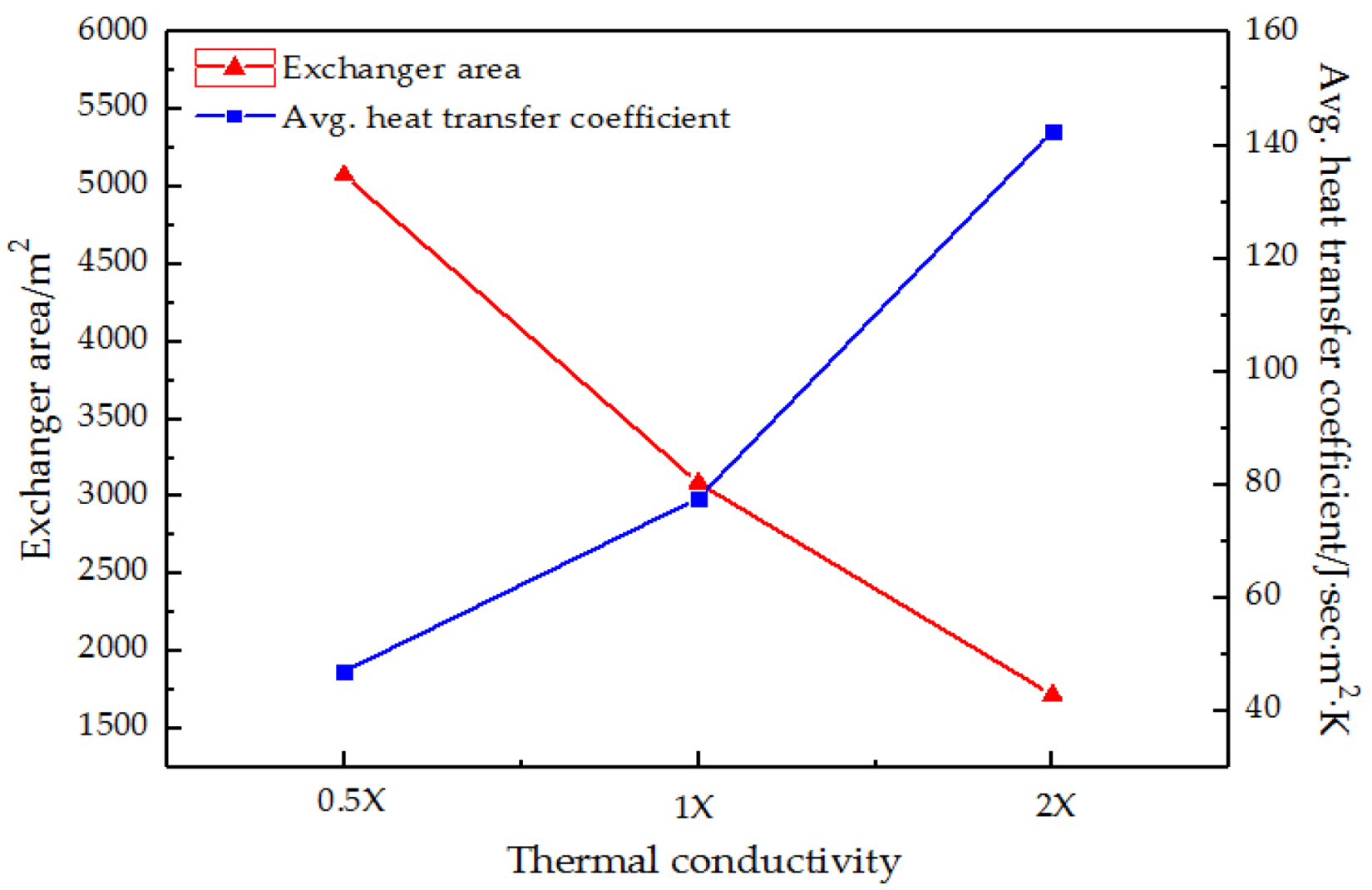
3.4.3. Heat Transfer Coefficient

In Figure 8, the larger the heat transfer coefficient, the smaller the exchanger area, and the larger the average convection heat transfer coefficient. When the heat exchanged is the same, the ionic liquid with a larger heat transfer coefficient has a stronger collision between molecules, which is more advantageous for heat transfer. In other words, the average convection heat transfer coefficient is larger and the area of the heat exchanger required for heat transfer under the same conditions is smaller.

4. Conclusions

In conclusion, this paper uses Aspen Plus to simulate and evaluate the process of CO2 capture in flue gas from oxy-fuel combustion power plants. The results show that the volume fraction of CO2 in the exhaust gas is less than 2% when the liquid–gas ratio is 1.55 (molar/molar), and the desorption efficiency is 98.2%. The mass purity of the CO2 product is 99.9% when the desorption pressure is 0.01 MPa. When the load efficiency is 0.45 mol CO2·mol1 IL, the product purity is 99.9%, the lean circulation is 46.65 kmol·h−1·t−1 CO2; this saves 76% in energy consumption compared to air–fuel combustion (the total energy consumption is 112.27 kWh·t1 CO2) and saves 81% compared to air–fuel combustion. In terms of lean circulation and energy consumption, oxy-fuel combustion capture is a more economical choice.
Section 3 not only finds application scenarios for ionic liquids, but also guides the design of ionic liquids on this base. It was assumed that the solubility of CO2 in the ionic liquid is the same in all cases, and the simulation was performed for different physical parameters—0.5, 1, and 2 times. The effects of ionic liquid properties on process lean circulation and energy consumption are discussed. In terms of density, when the density is increased, the circulation and energy consumption of the liquid solvent are correspondingly reduced. For the heat capacity at constant pressure, it is found that both lean circulation and energy consumption are reduced when the heat capacity is increased at a constant pressure. To reduce energy consumption, an ionic liquid with a relatively low density and heat capacity at a constant pressure should be selected as the absorbent. On the other hand, the effects of ionic liquid properties on heat exchanger design are also explored. If the minimum heat transfer area and the maximum convective heat transfer coefficient are to be achieved, it is preferable to select an ionic liquid having higher density, stronger thermal conductivity, and higher heat capacity at constant pressure. Therefore, in the future, more suitable ionic liquids can be designed based on these findings. It is undeniable that some other properties of the absorbents also affect the CO2 absorption capacity, especially functional group type and functional group density. Future work will be carried out in this direction.
This paper provides a feasible idea for carbon capture during oxy-fuel combustion. The low energy consumption of the process also provides a new way for energy conservation and emission reduction in the future. The simulation results of Aspen Plus show that the use of ionic liquid as an absorbent has a good application prospect. Simulation and evaluation results will guide engineering applications and ionic liquid design.

Supplementary Materials

The following supporting information can be downloaded at: https://www.mdpi.com/article/10.3390/separations9040095/s1, Table S1: The properties of ionic liquid solvent.

Author Contributions

Conceptualization, N.A.; methodology, Q.J. and L.L.; software, X.H.; validation, J.R.; data curation, X.H.; writing—original draft preparation, X.H.; writing—review and editing, J.W. and N.A.; project administration, Q.W. All authors have read and agreed to the published version of the manuscript.

Funding

This work was supported by [Zhejiang Provincial Natural Science Foundation of China #1] under Grant [LY16B060014]; and [State Key Laboratory of Chemical Engineering and the Innovation and Development of Marine Economy Demonstration #2] under Grant [No. SKL-ChE-08A01].

Institutional Review Board Statement

Not applicable.

Informed Consent Statement

Not applicable.

Data Availability Statement

Not applicable.

Acknowledgments

This work is supported and funded by the Zhejiang Provincial Natural Science Foundation of China (LY16B060014), the State Key Laboratory of Chemical Engineering, and the Innovation and Development of Marine Economy Demonstration (No. SKL-ChE-08A01). The authors would also like to acknowledge everyone who provided helpful guidance and thank the anonymous reviewers for their useful comments.

Conflicts of Interest

There are no conflicts of interest regarding the publication of this article.

References

  1. Wijesiri, R.P.; Knowles, G.P.; Easmin, H.Y. Technoeconomic evaluation of a process capturing CO2 directly from air. Processes 2019, 7, 503. [Google Scholar] [CrossRef] [Green Version]
  2. Mohamed Mohsin, H.; Mohd Shariff, A.; Johari, K. 3-Dimethylaminopropylamine (DMAPA) mixed with glycine (GLY) as an absorbent for carbon dioxide capture and subsequent utilization. Sep. Purif. Technol. 2019, 222, 297–308. [Google Scholar] [CrossRef]
  3. Al-Ghussain, L. Global warming: Review on driving forces and mitigation. Environ. Prog. Sustain. Energy 2019, 38, 13–21. [Google Scholar] [CrossRef] [Green Version]
  4. Han, T.; Zhao, R.; Zhang, S.; Hai, Y.X.; Liao, H.Y. Research and application on carbon capture of coal-fired power plants. Coal Eng. 2017, 49, 24. [Google Scholar]
  5. Lian, J.H. Study on CO2 Capture Combined with Sulfuric acid Nitric Acid in Biomass Oxyfuel Combustion Flue Gas. Master’s Thesis, Hebei University of Technology, Tianjin, China, 2015. [Google Scholar]
  6. Pehnt, M.; Henkel, J. Life cycle assessment of carbon dioxide capture and storage from lignite power plants. Int. J. Greenh. Gas Control 2009, 3, 49–66. [Google Scholar] [CrossRef]
  7. Wang, Y.; Zhao, L.; Otto, A.; Robinius, M.; Stolten, D. A review of post-combustion CO2 capture technologies from coal-fired power plants. Energy Procedia 2017, 114, 650–665. [Google Scholar] [CrossRef]
  8. Toftegaard, M.B.; Brix, J.; Jensen, P.A.; Glarborg, P.; Jensen, A.D. Oxy-fuel combustion of solid fuels. Prog. Energy Combust. Sci. 2010, 36, 581–625. [Google Scholar] [CrossRef]
  9. Portillo, E.; Alonso-Farinas, B.; Vega, F.; Cano, M.; Navarrete, B. Alternatives for oxygen-selective membrane systems and their integration into the oxy-fuel combustion process: A review. Sep. Purif. Technol. 2019, 229, 115708. [Google Scholar] [CrossRef]
  10. Eveloy, V. Hybridization of solid oxide electrolysis-based power-to-methane with oxyfuel combustion and carbon dioxide utilization for energy storage. Renew. Sustain. Energy Rev. 2019, 108, 550–571. [Google Scholar] [CrossRef]
  11. Buhre, B.J.P.; Elliott, L.K.; Sheng, C.D.; Gupta, R.P.; Wall, T.F. Oxy-fuel combustion technology for coal-fired power generation. Prog. Energy Combust. Sci. 2005, 31, 283–307. [Google Scholar] [CrossRef]
  12. Zeng, J.; Pan, S.C.; Ran, S.M. Development and research of 35 MW oxyfuel burning coal powder pot. Dongfang Electr. Rev. 2016, 4, 24–28. [Google Scholar]
  13. Châtel-Pélage, F.; Varagani, R.; Pranda, P.; Perrin, N.; Farzan, H.; Vecci, S.J.; Yongqi, L.; Chen, S.; Rostam-Abadi, M.; Bose, A.C. Applications of oxygen for NOx control and CO2 capture in coal-fired power plants. Therm. Sci. 2006, 10, 119–142. [Google Scholar] [CrossRef]
  14. Sarbassov, Y.; Duan, L.B.; Manovic, V.; Anthony, E.J. Sulfur trioxide formation/emissions in coal-fired air- and oxy-fuel combustion processes: A review. Greenh. Gases Sci. Technol. 2018, 8, 402–428. [Google Scholar] [CrossRef]
  15. Nemitallah, M.A.; Habib, M.A.; Badr, H.M.; Said, S.A.; Jamal, A.; Ben-Mansour, R.; Mokheimer, E.M.A.; Mezghani, K. Oxy-fuel combustion technology: Current status, applications, and trends. Int. J. Energy Res. 2017, 41, 1670–1708. [Google Scholar] [CrossRef]
  16. Ditaranto, M.; Hals, J. Combustion instabilities in sudden expansion oxy–fuel flames. Combust. Flame 2006, 146, 493–512. [Google Scholar] [CrossRef]
  17. Zhao, R.; Li, Y.B.; Chen, Y.B. Experimental study on integrated combustion desulfurization and denitrification of oxy-combustion simulated flue gas. Electr. Power 2016, 49, 170. [Google Scholar]
  18. Herzog, H.; Golomb, D.; Zemba, S. Feasibility, modeling and economics of sequestering power plant CO2 emissions in the deep ocean. Environ. Prog. 1991, 10, 64–74. [Google Scholar] [CrossRef]
  19. Cau, G.; Tola, V.; Ferrara, F.; Porcu, A.; Pettinau, A. CO2-free coal-fired power generation by partial oxy-fuel and post-combustion CO2 capture: Techno-economic analysis. Fuel 2018, 214, 423–435. [Google Scholar] [CrossRef]
  20. Shaddix, C.R.; Molina, A. Particle imaging of ignition and devolatilization of pulverized coal during oxy-fuel combustion. Proc. Combust. Inst. 2009, 32, 2091–2098. [Google Scholar] [CrossRef]
  21. Andersen, J.; Rasmussen, C.L.; Giselsson, T.; Glarborg, P. Global combustion mechanisms for use in CFD modeling under oxy-fuel conditions. Energ Fuel 2009, 23, 1379–1389. [Google Scholar] [CrossRef]
  22. Tran, K.Q.; Trinh, T.N.; Bach, Q.V. Development of a biomass torrefaction process integrated with oxy-fuel combustion. Bioresour. Technol 2016, 199, 408–413. [Google Scholar] [CrossRef] [PubMed]
  23. Niu, S.B.; Chen, M.Q.; Li, Y.; Xue, F. Evaluation on the oxy-fuel combustion behavior of dried sewage sludge. Fuel 2016, 178, 129–138. [Google Scholar] [CrossRef]
  24. Park, S.K.; Kim, T.S.; Sohn, J.L.; Lee, Y.D. An integrated power generation system combining solid oxide fuel cell and oxy-fuel combustion for high performance and CO2 capture. Appl. Energy 2011, 88, 1187–1196. [Google Scholar] [CrossRef]
  25. Glarborg, P.; Bentzen, L.L.B. Chemical effects of a high CO2 concentration in oxy-fuel combustion of methane. Energ Fuel 2008, 22, 291–296. [Google Scholar] [CrossRef]
  26. Mukherjee, S.; Kumar, P.; Yang, A.; Fennell, P. Energy and exergy analysis of chemical looping combustion technology and comparison with pre-combustion and oxy-fuel combustion technologies for CO2 capture. J. Environ. Chem. Eng. 2015, 3, 2104–2114. [Google Scholar] [CrossRef] [Green Version]
  27. Fytianos, G.; Ucar, S.; Grimstvedt, A.; Hyldbakk, A.; Svendsen, H.F.; Knuutila, H.K. Corrosion and degradation in MEA based post-combustion CO2 capture. Int. J. Greenh. Gas Control 2016, 46, 48–56. [Google Scholar] [CrossRef]
  28. Basha, O.M.; Keller, M.J.; Luebke, D.R.; Resnik, K.P.; Morsi, B.I. Development of a conceptual process for selective CO2 capture from fuel gas streams using [hmim][Tf2N] ionic liquid as a physical solvent. Energ Fuel 2013, 27, 3905–3917. [Google Scholar] [CrossRef]
  29. Silveira, A.J.; Pereda, S.; Tavares, F.W. A molecular dynamics study of the solvation of carbon dioxide and other compounds in the ionic liquids [emim][B(CN)4] and [emim][NTf2]. Fluid Phase Equilibria 2019, 491, 1–11. [Google Scholar] [CrossRef] [Green Version]
  30. Ma, T.; Wang, J.; Du, Z. A process simulation study of CO2 capture by ionic liquids. Int. J. Greenh. Gas. Con. 2017, 58, 223–231. [Google Scholar] [CrossRef]
  31. Vijayraghavan, R.; Pas, S.J.; Izgorodina, E.I. Diamino protic ionic liquids for CO2 capture. Phys. Chem. Chem. Phys. 2013, 15, 19994–19999. [Google Scholar] [CrossRef]
  32. Chaban, V.V.; Andreeva, N.A. Amination of five families of room-temperature ionic liquids: Computational thermodynamics and vibrational spectroscopy. J. Chem. Eng. Data 2016, 61, 1917–1923. [Google Scholar] [CrossRef]
  33. Lanyi, S. Chemical Process Simulation Training—Aspen Plus Tutorial, 2nd ed.; Chemical Industry Press: Beijing, China, 2017. [Google Scholar]
  34. Li, L.; Huang, X.; Jiang, Q.; Xia, L.; Wang, J.; Ai, N. New process development and process evaluation for capturing CO2 in flue gas from power plants using ionic liquid [emim][Tf2N]. Chin. J. Chem. Eng. 2020, 28, 721–732. [Google Scholar] [CrossRef]
  35. Schilderman, A.M.; Raeissi, S.; Peters, C.J. Solubility of carbon dioxide in the ionic liquid 1-ethyl-3-methylimidazolium bis (trifluoromethylsulfonyl) imide. Fluid Phase Equilibria 2007, 260, 19–22. [Google Scholar] [CrossRef]
  36. Makino, T.; Kanakubo, M.; Masuda, Y.; Umecky, T.; Suzuki, A. CO2 absorption properties, densities, viscosities, and electrical conductivities of ethylimidazolium and 1-ethyl-3-methylimidazolium ionic liquids. Fluid Phase Equilibria 2014, 362, 300–306. [Google Scholar] [CrossRef]
  37. Wu, F.; Argyle, M.D.; Dellenback, P.A.; Fan, M. Progress in O2 separation for oxy-fuel combustion–A promising way for cost-effective CO2 capture: A review. Prog. Energy Combust. Sci. 2018, 67, 188–205. [Google Scholar] [CrossRef]
  38. Zhou, C.; Shah, K.; Song, H.; Zanganeh, J.; Doroodchi, E.; Moghtaderi, B. Integration options and economic analysis of an integrated chemical looping air separation process for oxy-fuel combustion. Energ Fuel 2016, 30, 1741–1755. [Google Scholar] [CrossRef]
  39. Shah, K.; Moghtaderi, B.; Wall, T. Effect of flue gas impurities on the performance of a chemical looping based air separation process for oxy-fuel combustion. Fuel 2013, 103, 932–942. [Google Scholar] [CrossRef]
  40. Kang, S.; Chung, Y.G.; Kang, J.H.; Song, H. CO2 absorption characteristics of amino group functionalized imidazolium-based amino acid ionic liquids. J. Mol. Liq. 2020, 297, 111825. [Google Scholar] [CrossRef]
  41. Wei, L.; Guo, R.F.; Tang, Y.Q.; Zhu, J.M.; Liu, M.Y.; Chen, J.Q.; Xu, Y. Properties of aqueous amine based protic ionic liquids and its application for CO2 quick capture. Sep. Purif. Technol. 2020, 239, 116531. [Google Scholar] [CrossRef]
Figure 1. Process flow diagram for CO2 capture using [emim][Tf2N].
Separations 09 00095 g001
Figure 2. Temperature and liquid flowrate profiles of absorber. The red line represents the liquid flow while the black line represents the temperature.
Separations 09 00095 g002
Figure 3. Effect of [emim][Tf2N] density on solvent circulation and energy consumption. The red represents the solvent consumption and the shaded part represents the electrical power consumption.
Separations 09 00095 g003
Figure 4. Influence of heat capacity at constant pressure of [emim][Tf2N] on the temperature distribution curve of absorber. Black represents 0.5X, red represents 1X, and blue represents 2X.
Separations 09 00095 g004
Figure 5. The influence of heat capacity at a constant pressure of [emim][Tf2N] on the volume of solvent circulation and energy consumption. The red areas represent solvent consumption and the shaded areas represent electrical power consumption.
Separations 09 00095 g005
Figure 6. Effect of density of [emim][Tf2N] on the heat exchanger area and the average heat transfer coefficient of the heat exchanger. The red represents the exchanger area and the blue represents the average heat transfer coefficient.
Separations 09 00095 g006
Figure 7. Effect of constant pressure heat capacity of [emim][Tf2N] on the heat transfer area and the average heat transfer coefficient of the heat exchanger. The red represents the exchanger area and the blue represents the average heat transfer coefficient.
Separations 09 00095 g007
Figure 8. Effect of thermal conductivity of [emim][Tf2N] on the heat exchanger area and the average heat transfer coefficient of the heat exchanger. The red represents the exchanger area and the blue represents the average heat transfer coefficient.
Separations 09 00095 g008
Table 1. Correlations and parameters developed for various properties of [emim][Tf2N].
PropertyUnitsCorrelationParametersData
Densityg·cm−3 ρ i = M i p c i R T c i Z i * , RA ( 1 + ( 1 T r ) 2 / 7 ) Z i * , RA 0.272
Heat CapacityJ·mol−1·K−1 C p i = C 1 i + C 2 i T + C 3 i T 2 C 1 i 329.328
C 2 i 0.849
C 3 i −0.000768
ViscositymPa·s ln η i = A i + B i T + C i ln ( T ) A i −138.104
B i 9054.914
C i 19.524
Vapor
Pressure
MPa ln p i s = C 1 i + C 2 i T C 1 i 28.375
C 2 i −15130
Thermal
Conductivity
W·m−1·K−1 λ i = C 1 i + C 2 i T + C 3 i T 2 C 1 i 0.134
C 2 i −6.13 × 10⁵
C 3 i 4.957 × 10⁻⁸
Surface
Tension
mN·m−1 σ i = C 1 i ( 1 T T c i ) ( C 2 i + C 3 i T r i + C 4 i T r i 2 + C 5 i T r i 3 ) C 1 i 103.234
C 2 i 15.613
C 3 i −92.955
C 4 i 234.092
C 5 i −204.914
Table 2. Parameters of temperature-dependent Henry constants.
Component iComponent AaiAbiAciAdiAeiA
CO2[emim][Tf2N]82.1490.00517−12.9540.00517−874,200
Table 3. NRTL binary parameters of CO2 with [emim][Tf2N].
Component iComponent Aaijajibijbji
CO2[emim][Tf2N]1.267−4.903−671.2821685.225
Table 4. Flue gas composition.
ComponentsFlue Gas V [%]
N27
CO280
O26.5
H2O6.5
Table 5. Key parameters for the CO2 capture of the main equipment.
DescriptionUnit
Absorption tower
   Stages8
   Pressure drop0.02 MPa
   IL-IN feeding positionOn stage 1
   Feeding positionOn stage 8
Flash tank
   Heat load0 kW
Multi-stage compressor unit
   Compressor stage5
   Interstage cooler temperature308 K
   TypesMcompr(Isentropic)
   Net work101.41 kW·t−1 CO2
Pump
   Net work4.246 kW·t−1 CO2
Exchanger
   Net work6.62 kW·t−1 CO2
Table 6. Comparison between post-combustion capture and oxy-fuel combustion capture.
Post-Combustion CaptureOxy-Fuel Combustion Capture
Load efficiency0.36 mol CO2·mol−1 IL0.45 mol CO2·mol−1 IL
Product purity99.9%99.9%
Lean circulation191.1 kmol·h−1·t−1 CO246.65 kmol·h−1·t−1 CO2
Energy consumption604.2 kW·h·t−1 CO2112.276 kW·h·t−1 CO2
Publisher’s Note: MDPI stays neutral with regard to jurisdictional claims in published maps and institutional affiliations.

