Abstract
In view of the difficulty of traditional hydrocyclones to meet the requirements of fine classification, a double-overflow three-product (internal overflow, external overflow and underflow) hydrocyclone was designed in this study. Numerical simulation and experimental research methods were used to investigate the effects of double-overflow flow field characteristics and structural parameters (i.e., internal vortex finder diameter and insertion depth) on separation performance. The research results showed that the larger the diameter of the internal vortex finder, the greater the overflow yield and the larger the cut size. The finest internal overflow product can be obtained when the internal vortex finder is 30 mm longer than the external vortex finder. The separation efficiency is highest when the internal vortex finder is 30 mm shorter than the external vortex finder.
1. Introduction
A hydrocyclone is a device for sorting materials of either different particle sizes, densities, or both, by the principle of centrifugal sedimentation [1,2,3]. The suspension containing solid particles is fed tangentially into the hydrocyclone at a certain speed and pressure to form a high-speed rotating vortex [4]. After these rotating fluids enter the cone section of the hydrocyclone, and as the inner diameter of the cone section of the hydrocyclone gradually shrinks, the downward rotation speed of the fluid is continuously increased, resulting in unequal pressure along the radial direction. The pressure is lower close to the axis, while it is higher near the sidewall of the hydrocyclone [5]. The size and density of the particles contained in the suspension entering the hydrocyclone are different, and thus they are subjected to different centrifugal forces and centripetal buoyancy. Particles with small particle size and low density move under the action of centripetal buoyancy to the axis of lower pressure, forming an internal swirling flow in the spiral direction and are discharged from the overflow port [6]. Particles with large particle size and a high density move to the sidewall of the hydrocyclone under the action of centrifugal force, forming an external swirling flow spiraling downward along the wall of the hydrocyclone and discharging from the underflow port, thereby completing the separation process [7]. A hydrocyclone has the advantages of simple structure [8], high separation efficiency [9], small footprint [10], and low operating cost [11]. As a result, they are widely used in mining [12], chemical engineering [13], coal separation [14], environmental protection [15], bioengineering [16], and for other similar industrial applications.
Once the structural size of a hydrocyclone is determined, and the cut size is also determined [17]. Particles that are smaller than the cut size enter the overflow, and particles that are larger than the cut size enter the underflow. In this way, the traditional hydrocyclone can separate the underflow and overflow products. It is worth noting that the working principle of hydrocyclones determines that the separation process is not a complete separation [18]. This will make the particles with sizes close to the cut size either enter the overflow or enter the underflow, resulting in the classification accuracy not meeting fine grading requirements [19]. With the continuous expansion of the field of application of hydrocyclones, new requirements have been put forward for the hydrocyclone separation process, and now it is hoped to obtain fine-grained, narrow-grain ranged products [20,21]. For this reason, the current practice is to use a multi-stage hydrocyclone series or parallel combination process [22,23,24] for secondary grading to obtain multi-stage narrow particle size products. However, the above separation method increases the footprint of the equipment, resulting in such problems as long process flow, large equipment investment, high energy consumption, and unstable separation efficiency, which limits, to some extent, the application and development of hydrocyclones [25].
In order to solve the above problems and achieve the goal of fine grading, the development of a narrow grain-size range multi-product hydrocyclone and the grading process has attracted the attention of researchers [26,27]. Obeng et al. [28] developed a hydrocyclone with a double overflow and a single underflow structure and performed a test study on it with the objective of reducing the fine-grained particle content of the underflow and increasing the yield of the high-quality fine-grain overflow. Becker et al. [29] inserted a small diameter coaxial vortex finder into the center of a traditional hydrocyclone to form an internal and external double-vortex finder structure. During the separation process, the particles were enriched in each outlet product according to fractional and specific gravity selectivity, and the underflow, internal overflow, and external overflow, were separated at a time. Separating the upper group 2 chromitite (UG2) ore from South Africa with a three-product hydrocyclone solves the problem of excessive circulation load in the grinding system and provides favorable conditions for subsequent flotation operations. Ahmed et al. [30] introduced a three-product hydrocyclone with a double underflow and single overflow and conducted a system test. The fitted equations predicted the yield of each outlet product. The potential application of the hydrocyclone in actual production was also described.
Although a double vortex finder hydrocyclone can obtain three narrow-size products of different particle sizes at a time, the existence of the internal vortex finder makes the flow field and particle movement in the hydrocyclone more complicated. The instability of the hydrocyclone separation process is increased and the separation mechanism is still unclear. Therefore, it was necessary to study the influence of the distribution characteristics of the flow field on the separation mechanism, as well as the influence of the structural parameters, and especially the influence on the separation performance of the diameter of the vortex finder and the depth of its insertion. In the present investigation, the characteristics of the internal flow field and the particle distribution pattern of the double vortex finder hydrocyclone were studied by numerical simulation and with experimental test methods. The findings from the present study are expected to provide a theoretical basis and reference values for multi-product hydrocyclone separation processes and an insight into the hydrocyclone separation mechanism.
2. Materials and Methods
2.1. Double-Overflow Three-Product Hydrocyclone
In the present investigation, a Φ150 mm double-overflow three-product hydrocyclone was designed. The structural parameters of the hydrocyclone are shown in Table 1. The structure schematic is shown in Figure 1a. The feed port was in the form of a rectangular tangential feed.

Table 1.
Structure parameters of double overflow three-product hydrocyclone.
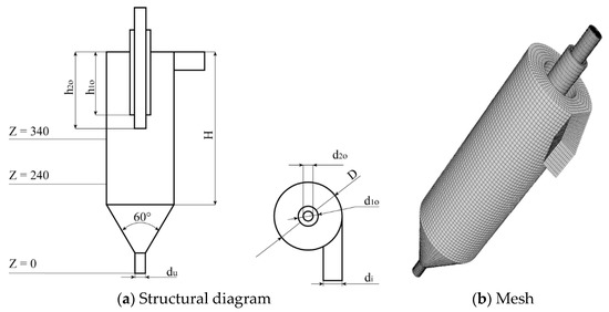
Figure 1.
Structural diagram and mesh of a double-overflow three-product hydrocyclone.
When establishing the three-dimensional model of the hydrocyclone flow field, the center of the underflow port of the hydrocyclone is set as the coordinate origin and the hydrocyclone axis is along the positive direction of the Z-axis. Two cross-sections at Z = 240 mm and Z = 340 mm were selected as the data analysis sections.
2.2. Simulation Conditions
ANSYS ICEM CFD (version 14.5) software was used to mesh the hydrocyclone flow field model, adopting the hexahedral structured mesh division method. Local mesh refinement was performed for locations such as the sidewalls and underflow port. The meshing result is shown in Figure 1b. The number of meshes was 126,372. The hydrocyclone inlet and outlet were set to “velocity-inlet” and “pressure-outlet”, respectively. The inlet speed was 4 m/s, the overflow port, and the underflow port, are connected to the atmosphere, the pressure of which was taken as 1.0 atm. The slurry was taken as a mixture of water and quartz sand particles with a water density of 998 kg/m3 and a quartz sand particle density of 2650 kg/m3. The main phase was set to water and the secondary phase was set to quartz sand particles. The feed mass concentration is 17.5%, and the volume fraction of the solid phase particles obtained is about 7.5%. The particle size distribution of quartz sand is shown in Table 2. In order to save computing resources, the following hypotheses are made for the numerical simulation conditions: the temperature field is constant; the fluid is not compressible; the interaction between particles and slurry viscosity are ignored; and the particles are assumed to be spherical particles.
Table 2.
Particle size distribution.
2.3. Simulated Solution Method
The turbulence model used in the simulation of the hydrocyclone flow field mainly included a standard k-ε model, an RNG (renormalized group) k-ε model, and an RSM (Reynolds stress model) model. The standard k-ε model and RNG k-ε model are not suitable for simulating the internal flow field of hydrocyclones [31]. The RSM accounts for the effects of streamline curvature, swirl, rotation, and rapid changes in strain rate in hydrocyclones [32], and abandoning the isotropic eddy-viscosity hypothesis; the RSM closes the Reynolds-averaged Navier−Stokes equations by solving transport equations for the Reynolds stresses, together with an equation for the dissipation rate. From the flow field comparisons in 75 mm, Hsieh and Rajamani [33], and 250 mm hydrocyclone [34], it can be concluded that the RSM model predictions are superior to the lower order or hybrid turbulence models for highly swirl-dominated flows. In the study, the turbulence model adopted the RSM model and the solution method used the pressure-based steady flow field calculation method. The pressure-speed coupling used the “SIMPLEC (semi-implicit method for pressure linked equations-consistent)” method, the pressure dispersion used the “PRESTO!” format, and the momentum dispersion used the “QUICK” format. The turbulent kinetic energy, turbulent dissipation rate, and Reynolds stress dispersion were all in the “one order upwind” format [35,36].
2.4. Experimental Test System
The experimental test system configuration is shown in Figure 2a. It is composed mainly of an agitator, a centrifugal pump, a pressure gauge, a flow meter, valves, a hydrocyclone, etc. The flow and pressure in the experimental system were controlled and regulated by valves on the centrifugal pump and piping.
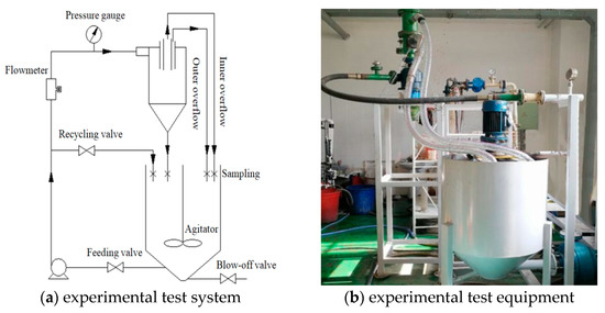
Figure 2.
Hydrocyclone separator system experimental configuration.
During the tests, the water and quartz sand were mixed in proportion and were then added into the barrel to prepare the slurry. After being agitated continuously by a stirrer, they formed a uniformly distributed suspension. After the suspension came out of the centrifugal pump, part of it was returned to the barrel through the return valve, and the other part was fed tangentially into the hydrocyclone from the hydrocyclone feed port through the flow meter and pressure gauge. After grading was completed, the liquid, rich in coarse solid particles, was discharged from the underflow port of the hydrocyclone and was then returned to the barrel. The liquid containing fine particles was discharged from the internal and external overflow ports of the hydrocyclone and also returned to the barrel, which ensured the cyclic operation of the test system. After the operation stabilized, samples were taken at the inlet, internal and external overflow ports, and underflow port of the hydrocyclone, and data analysis was performed. The test equipment is shown in Figure 2b.
2.5. Experimental Materials
Quartz sand powder with a density of 2650 kg/m3 was selected as the feed particles. The particle size distribution of the SiO2 powder was measured using the laser particle size analyzer (Malvern Mastersizer 2000, Malvern, England). Particle size distribution of the feed fitted by GaussAmp distribution function, is shown in Figure 3. As can be seen from Figure 3, the feed particles conform to the normal distribution, the median particles size are 39.8 μm, and most of the particle sizes are below 147 μm. The specific size distribution is shown in Table 3.
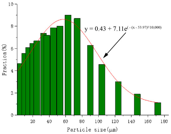
Figure 3.
SiO2 powder particle size distribution.
Table 3.
Quartz sand size distribution.
3. Results
3.1. Numerical Simulation Study
A large number of studies have been carried out on conventional single-overflow hydrocyclones, and consistent conclusions and research results have been obtained on the effects of structural parameters and operational parameters on the separation performance [37,38]. In the present study, on the basis of the traditional single vortex finder, a small diameter internal vortex finder was inserted concentrically to form a double-vortex finder structure. The introduction of the internal vortex finder inevitably will affect the flow field and separation performance. Therefore, it is necessary to investigate the influence of the structural size of the internal vortex finder on the separation performance, in order to provide the basis and reference for the optimal design of the hydrocyclone with double-vortex finder. All simulations were performed using ANSYS Fluent (version 14.5).
3.1.1. Influence of Vortex Finder Diameter on Separation Performance
The depth of the vortex finder was set to be the same and flush with the external vortex finder (the insertion depth was 140 mm). By changing the diameters of the internal vortex finders to 22 mm, 24 mm, 26 mm, and 28 mm, the influence of the diameter of the internal vortex finder on the flow field performance of the hydrocyclone could be investigated. All models only change the size of the internal vortex finder and keep the same working condition.
The axial velocity distribution curves for different internal vortex finder diameters in section Z = 240 mm and Z = 340 mm are shown in Figure 4. From the perspective of the overall distribution of axial velocity, the axial velocity can be divided into positive and negative parts. In the outer swirl region, the region near the hydrocyclone wall, the axial velocity was negative, indicating a downward movement of the fluid. In the inner swirl region, which was the region near the axis of the hydrocyclone, the axial velocity was positive, indicating that the fluid will move upward. This phenomenon indicates that there must be an interface with zero velocity at the junction of the inner swirl and outer swirl regions, and fluid passing through this interface will change its direction of motion. This is basically consistent with the axial velocity distribution of the traditional single overflow hydrocyclone [39]. The relationship between the axial velocity and the radial position of the hydrocyclone can be analyzed from Figure 4. In the outer swirl region, that is, when the axial velocity was negative, the axial velocity changes relatively smoothly and was hardly affected by the radial position change of the hydrocyclone. When the fluid passes through the point where the axial velocity is zero, in the inner swirl region where the axial velocity is positive, the axial velocity increases sharply as the radius of the swirler decreases. It can also be seen from Figure 4b that after the axial velocity reaches the maximum value, under the disturbance of the vortex finder, it begins to decrease sharply as the radius decreases until the minimum value is reached near the axis. From the influence of the diameter of the internal vortex finder on the axial velocity, it can be seen that the axial velocity of the outer swirl region is hardly affected by the variation of the diameter of the internal vortex finder. The axial velocity of the inner swirl region increases as the diameter of the internal vortex finder increases. In the Z = 240 mm section, the internal vortex finder diameter increases from 22 to 28 mm, and the maximum axial velocity increases from 1.59 to 2.23 m/s. In the Z = 340 mm section, the maximum axial velocity increases from 2.15 to 2.56 m/s. The reason for this behavior is that as the diameter of the internal vortex finder increases, the flow rate of the fluid passing through the unit cross-section increases so that the axial velocity increases as the diameter of the internal vortex finder increases. Acquisition of this variation rule can provide theoretical guidance for the application of the hydrocyclone. That is, if it is necessary to increase the internal overflow yield, the diameter of the internal vortex finder can be appropriately increased. However, the excessive diameter of the internal vortex finder will increase the axial velocity and reduce the residence time of the particles in the hydrocyclone so that separation of the particles is not complete, and the separation precision is lowered.
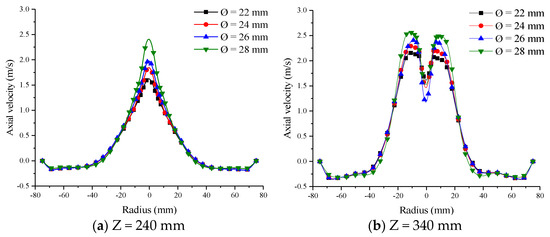
Figure 4.
Axial velocity distributions for different internal vortex finder diameter.
A diagram showing the distribution of particles in a hydrocyclone with different internal vortex finder diameters is given in Figure 5. Figure 5a,b are particle cloud images for particle sizes of 15 μm and 30 μm, respectively. As can be seen from the figures, as the diameter of the internal vortex finder increases, the particles gradually move upward from the bottom of the hydrocyclone. The larger the diameter of the internal vortex finder, the more particles accumulate at the overflow port, especially for the movement of 30 μm particles to the overflow port. This behavior had two effects on the separation performance: First, particles collected near the underflow port move upward as the diameter of the internal vortex finder increased, so that more particles participate in the separation process. This is beneficial to improving the separation effect, instead of a large proportion of the particles accumulating in the vicinity of the underflow port, which are discharged directly from the underflow port without being sufficiently separated. Second, coarse particles that have already accumulated in the underflow may be mistakenly brought into the overflow during the upward movement, resulting in an increase in the overflow mismatch product, which is not conducive to the fine grading of the particles.
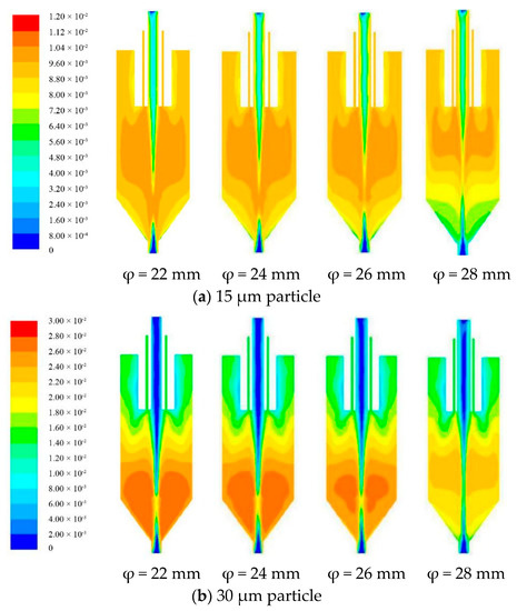
Figure 5.
Particle distributions for different internal vortex finder diameters.
The effect of the diameter of the internal vortex finder on the internal overflow yield is shown in Figure 6. The internal overflow yield is the sum of the ratio of particles at each level to the feed particles. It can be observed that the overflow yield increases as the diameter of the internal vortex finder increases. As the diameter of the internal vortex finder is increased from 22 to 28 mm, the internal overflow yield increases from 5.19% to 12.78%. Figure 7 is the internal overflow particle size curve for different internal vortex finder diameters. It can be observed that the cut size (d50) of the internal overflow increases as the diameter of the internal vortex finder increases. As the internal vortex finder diameter increased from 22 to 28 mm, the cut size increased from 12.5 to 18.9 μm. It can be deduced from the analysis that the diameter of the internal vortex finder affects not only the internal overflow yield but also the size grading. Therefore, the diameter of the internal vortex finder must be appropriately selected.
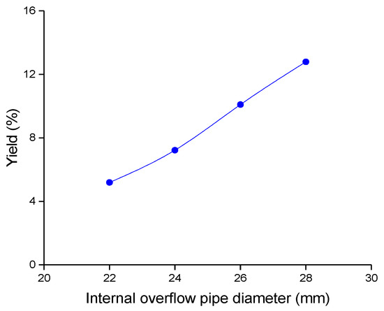
Figure 6.
Effect of internal vortex finder diameter on internal overflow yield.
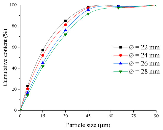
Figure 7.
Effect of internal vortex finder diameter on internal overflow particle size.
3.1.2. Influence of Vortex Finder Insertion Depth on Separation Performance
In the present study, the internal vortex finder had a diameter of 22 mm and the internal and external vortex finder had an insertion depth of 140 mm, and this position was used as a reference interface (0 mm). The value is negative when the internal vortex finder is shorter than the external vortex finder, and the value is positive when the internal vortex finder is longer than the external vortex finder. Four insertion depths of the vortex finder are selected, which are −90 mm, −30 mm, 30 mm, and 90 mm, respectively (the insertion depths of internal vortex finder are 50 mm, 110 mm, 170 mm, and 230 mm, respectively). The influence of the depth of the internal vortex finder on the swirl separation performance was simulated.
Figure 8a,b represents the curves showing the influence of the insertion depth change of the internal vortex finder on the axial velocity at sections Z = 240 mm and Z = 340 mm, respectively. As can be seen from the figure, in the outer swirl region, that is, the region where the axial velocity was negative, the insertion depth of the internal vortex finder had little effect on the axial velocity. In the inner swirl region, that is, the region where the axial velocity was positive when the internal vortex finder was longer than the external vortex finder, the axial velocity was small. This can prolong the residence time of the particles in the hydrocyclone, making the separation of the particles more thorough, thereby improving the separation accuracy of the hydrocyclone. When the internal vortex finder is shorter than the external vortex finder, the axial velocity is larger, which is favorable for the improvement of the overflow yield.
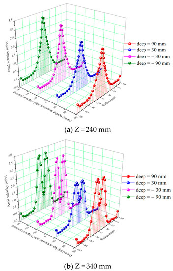
Figure 8.
Axial velocity distribution in different inner vortex finder insertion depths.
A diagram showing the particle distribution of the hydrocyclones with different insertion depths of the internal vortex finder is presented in Figure 9. It can be observed from the figure that when the internal vortex finder is shorter than the external vortex finder, that is, the depth of the internal vortex finder is −90 mm and −30 mm, the insertion depth has little effect on the distribution of particles having a particle size of 15 μm. However, it has a certain influence on the particle distribution for particles of size 30 μm. As the insertion depth of the vortex finder increases, the particles tend to move downward. When the internal vortex finder is longer than the external vortex finder, i.e., when the internal vortex finder depth is 30 mm or 90 mm, the greater the insertion depth, the more evident the movement tendency is of the particles toward the underflow port. A large proportion of the particles accumulate in the underflow port, which is not conducive to the good grading of the particles.
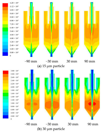
Figure 9.
Particle distributions with different insertion depths of the inner vortex finders.
Figure 10 is the internal overflow yield curve for different internal vortex finder insertion depths. It can be deduced from Figure 10 that the internal overflow yield is larger when the internal vortex finder is shorter than the external vortex finder. As the insertion depth increases, the underflow rate first decreases and then increases. The yield is minimal when the insertion depth is 30 mm, which is 6.48%. The internal overflow particle size curve for different internal vortex finder insertion depths is shown in Figure 11. It can be seen that when the internal vortex finder is shorter than the external vortex finder, the deeper the insertion, the smaller the granularity classification is. When the internal vortex finder is longer than the external vortex finder, the shallower the insertion, the smaller the granularity classification is. The granularity classification was smallest when the insertion depth was 30 mm.
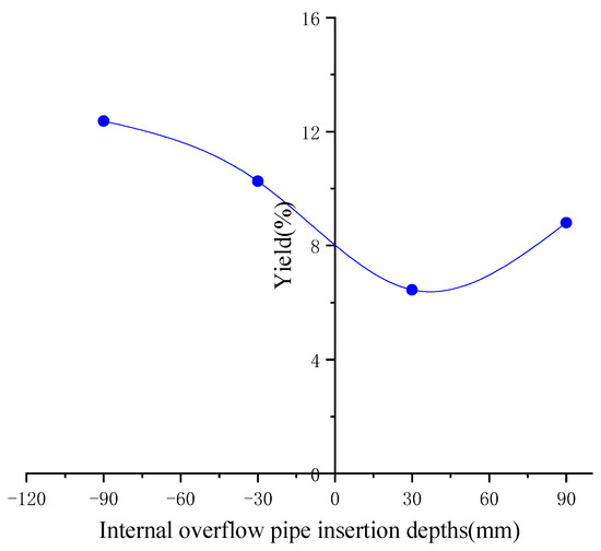
Figure 10.
Internal overflow yield of different internal vortex finder insertion depths.
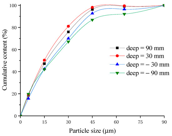
Figure 11.
Inner-overflow yield and particle classification for different inner vortex finder insertion depths.
3.2. Experimental Study on Separation Performance
The slurry mass concentration was set at 18% during the test and the feed pressure to the hydrocyclone was adjusted to 0.10 MPa by means of a centrifugal pump and an in-line valve.
In order to verify whether the double-overflow hydrocyclone can obtain three kinds of particle size products, particle size composition analyses were carried out on samples from the internal overflow port, the external overflow port, and the underflow port of the hydrocyclone. The particle size distribution is shown in Figure 12. It can be seen from the figure that after grading by the double-vortex finder hydrocyclone, narrow-grain products with cut sizes of 15.3 μm, 22 μm, and 19.1 µm were obtained by one grading of the feedstock.
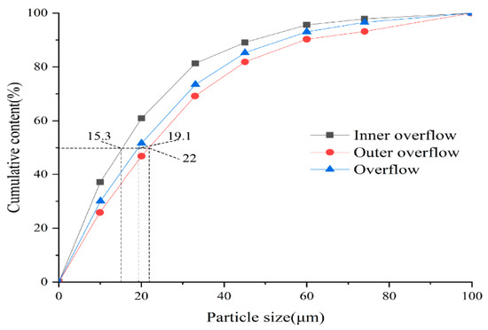
Figure 12.
Particle size distributions of the three products of a double-overflow hydrocyclone.
3.2.1. Experimental Analysis of the Influence of the Internal Vortex Finder Diameter on the Separation Performance
The effects of internal vortex finder diameter variation on the overall efficiency and cut size of a hydrocyclone are shown in Table 4. Analysis of the data in the table indicates that when the diameter of the internal vortex finder was increased from 22 to 28 mm, the cut size increased from 37 to 48 μm and the overall efficiency increased from 50.69% to 53.66%. This was consistent with the results of the numerical simulations (see Figure 6 and Figure 7). Among them, the overflow efficiency calculation formula is shown in Equations (1) and (2).
where, a, b, and c refer to the −45 um particle size content in the feed, overflow, and underflow products, respectively.
Table 4.
Effect of changing the diameter of the inner vortex finder on the separation performance of a hydrocyclone.
Once the double vortex finder hydrocyclone has been graded to get two kinds of overflow products with different particle sizes, obviously the above formula cannot be directly applied, the −45 um particle size content in the internal and external overflow products is converted using the following formula:
where, is the calculated particle size (−45 um) content after internal and external overflow synthesis; λ1 and λ2 represent internal and external overflow yields, respectively.
3.2.2. Influence on the Separation Performance of the Insertion Depth of the Internal Vortex Finder
The effects of the insertion depth of the vortex finder on the cumulative content of the particles, the overall efficiency and the cut size are summarized in Table 5. By analysis of the data in the table it can be deduced that as the insertion depth of the vortex finder is increased, the particle size of the hydrocyclone first decreases and then increases slightly. The minimum cut size of 32 μm was achieved when the insertion depth was 30 mm. The overall grading efficiency first increased and then decreased with the increase in the insertion depth of the internal vortex finder. The grading efficiency was highest when the internal vortex finder was inserted to a depth of −30 mm. This was consistent with the findings of the numerical simulations.
Table 5.
Effects of inner vortex finder insertion depth on the separation. Performance of a hydrocyclone.
4. Conclusions
A double-overflow three-product hydrocyclone has been proposed that can obtain three different graded particle products in one separation. The problem of traditional hydrocyclones finding it difficult to achieve fine grading has been solved. Numerical simulations and physical experience were used to study the flow field and separation performance of double-overflow three-product hydrocyclones. The findings of the investigation were that as the internal vortex finder diameter is increased, the aggregation of the particles to the overflow port is more evident and overflow yield is also larger. The larger the internal vortex finder diameter, the larger is the cut size of the hydrocyclone. At the same time, it was found that when using Φ150 hydrocyclones for SiO2 separation, the finest internal overflow product can be obtained when the internal vortex finder is 30 mm longer than the external vortex finder. The gradation efficiency is the highest when the internal vortex finder is 30 mm shorter than the external vortex finder. Through the present study, it is evident that the flow field in a hydrocyclone becomes more complicated due to the complexity of the double-vortex finder structure. Thus, the influence of double-overflow hydrocyclones on particle motion and their capacity to enhance gradation performance merits further study.
Author Contributions
Conceptualization, Y.Z.; methodology, Y.Z. and B.C.; software, J.G. and H.W.; validation, L.J.; formal analysis, J.G.; investigation, Y.Z. and B.C.; resources, L.J. and J.Y.; writing—original draft preparation, Y.Z.; writing—review and editing, J.G., H.W., and L.J. All authors have read and agreed to the published version of the manuscript.
Funding
This research was funded by the Natural Science Foundation of Shandong Province, China (ZR2020ME105).
Institutional Review Board Statement
Not applicable.
Informed Consent Statement
Not applicable.
Data Availability Statement
The data that support the findings of this study are available from the corresponding author, (Yuekan Zhang), upon reasonable request.
Conflicts of Interest
The authors declare no conflict of interest.
References
- Sripriya, R.; Suresh, N.; Chakraborty, S.; Meikap, B.C. Improvement of performance efficiency of a hydrocyclone with design modification by suppressing air core. Korean J. Chem. Eng. 2011, 28, 225–231. [Google Scholar] [CrossRef]
- Svarovsky, L. Solid-Liquid Separation; Butterworths: London, UK, 1981. [Google Scholar]
- Wang, B.; Chu, K.W.; Yu, A.B. Numerical Study of Particle-Fluid Flow in a Hydrocyclone. Ind. Eng. Chem. Res. 2007, 46, 4695–4705. [Google Scholar] [CrossRef]
- Wang, C.; Ji, C.; Zou, J. Simulation and experiment on transitional behaviours of multiphase flow in a hydrocyclone. Can. J. Chem. Eng. 2015, 93, 1802–1811. [Google Scholar] [CrossRef]
- Laleh, A.; Seyfi, M.M.; Nezamedin, H.S.; Alireza, F.; Ehsan, S.; Mahmoud, H.; Maryam, K. Numerical and Experimental Biomass Separation from Fermentation Process by Minihydrocyclones. Chem. Eng. Technol. 2020, 44, 23–30. [Google Scholar]
- Wang, C.; Sun, X.; Shen, L.; Wang, G. Analysis and Prediction of Influencing Parameters on the Coal Classification Performance of a Novel Three Products Hydrocyclone Screen (TPHS) Based on Grey System Theory. Processes 2020, 8, 974. [Google Scholar] [CrossRef]
- Padhi, M.; Mangadoddy, N.; Sreenivas, T.; Vakamalla, T.R.; Mainza, A.N. Study on multi-component particle behaviour in a hydrocyclone classifier using experimental and computational fluid dynamics techniques. Sep. Purif. Technol. 2019, 229, 115698. [Google Scholar] [CrossRef]
- Tan, F.; Karagoz, I.; Avci, A. The Effects of Vortex Finder Dimensions on the Natural Vortex Length in a New Cyclone Separator. Chem. Eng. Commun. 2016, 203, 1216–1221. [Google Scholar] [CrossRef]
- Sripriya, R.; Kaulaskar, M.D.; Chakraborty, S.; Meikap, B.C. Studies on the performance of a hydrocyclone and modeling for flow characterization in presence and absence of air core. Chem. Eng. Sci. 2007, 62, 6391–6402. [Google Scholar] [CrossRef]
- Habibian, M.; Pazouki, M.; Ghanaie, H.; Abbaspour-Sani, K. Application of hydrocyclone for removal of yeasts from alcohol fermentations broth. Chem. Eng. J. 2008, 138, 30–34. [Google Scholar] [CrossRef]
- Sabbagh, R.; Lipsett, M.G.; Koch, C.R.; Nobes, D.S. An experimental investigation on hydrocyclone underflow pumping. Powder Technol. 2017, 305, 99–108. [Google Scholar] [CrossRef]
- Mokni, I.; Dhaouadi, H.; Bournot, P.; Mhiri, H. Numerical investigation of the effect of the cylindrical height on separation performances of uniflow hydrocyclone. Chem. Eng. Sci. 2015, 122, 500–513. [Google Scholar] [CrossRef]
- Narasimha, M.; Brennan, M.S.; Holtham, P.N. CFD modeling of hydrocyclones: Prediction of particle size segregation. Miner. Eng. 2012, 39, 173–183. [Google Scholar] [CrossRef]
- Chu, K.; Chen, J.; Yu, A. Applicability of a coarse-grained CFD–DEM model on dense medium cyclone. Miner. Eng. 2016, 90, 43–54. [Google Scholar] [CrossRef]
- Son, J.H.; Hong, M.; Yoo, H.C.; Kim, Y.I.; Kim, H.D.; Kim, J.T. A multihydrocyclone water pretreatment system to reduce suspended solids and the chemical oxygen demand. Desalin. Water Treat 2016, 57, 2996–3001. [Google Scholar] [CrossRef]
- Santos, S.; Jones, K.; Abdul, R.; Boswell, J.; Paca, J. Treatment of wet process hardboard plant VOC emissions by a pilot scale biological system. Biochem. Eng. J. 2007, 37, 261–270. [Google Scholar] [CrossRef]
- Tian, J.; Ni, L.; Song, T.; Olson, J.; Zhao, J. An overview of operating parameters and conditions in hydrocyclones for enhanced separations. Sep. Purif. Technol. 2018, 206, 268–285. [Google Scholar] [CrossRef]
- Ji, L.; Kuang, S.; Yu, A. Numerical Investigation of Hydrocyclone Feed Inlet Configurations for Mitigating Particle Misplacement. Ind. Eng. Chem. Res. 2019, 58, 16823–16833. [Google Scholar] [CrossRef]
- Shakeel, S.M.; Fateme, M.; Christopher, M.; Taylor Robert, A.; Ebrahimi, W.M. Particle movement and fluid behavior visualization using an optically transparent 3D-printed micro-hydrocyclone. Biomicrofluidics 2020, 14, 06416. [Google Scholar]
- Lianping, D.; Jianchuan, G.; Hongli, Y.; Jiang, F. Experimental study on the separation effect based on density in hydrocyclone and the classification effect based on size in water-only cyclone. J. China Coal Soc. 2014, 39, 954–960. [Google Scholar]
- Ying, R.; Yu, J.; Wang, W.; Zhang, T.; Feng, J.; Du, S. Optimization of structural and process parameters for fine particle classifying hydrocyclone. J. Mech. Eng. 2017, 53, 124–134. [Google Scholar] [CrossRef]
- Chen, J.; Jiang, Z.; Chen, J. Effect of Inlet Air Volumetric Flow Rate on the Performance of a Two-Stage Cyclone Separator. ACS Omega 2018, 3, 13219–13226. [Google Scholar] [CrossRef]
- Zhang, Y.; Liu, P.; Jiang, L.; Yang, X. The Study on Numerical Simulation and Experiments of Four Product Hydrocyclone with Double Vortex Finders. Minerals 2019, 9, 23. [Google Scholar] [CrossRef]
- Hwang, K.-J.; Lyu, S.-Y.; Nagase, Y. Particle separation efficiency in two 10mm hydrocyclones in series. J. Taiwan Inst. Chem. Eng. 2009, 40, 313–319. [Google Scholar] [CrossRef]
- Liu, Y.; Cheng, Q.; Zhang, B.; Feng, T. Three-phase hydrocyclone separator A review. Chem. Eng. Res. Des. 2015, 100, 554–560. [Google Scholar] [CrossRef]
- Liu, T.R.; Liu, P.K. The influence of inlet pressure control on separation performance of multiproduct cyclones. Open Mech. Eng. J. 2015, 9, 117–123. [Google Scholar] [CrossRef]
- Zhang, X.M.; Guo, D. Determination of design parameter for three-product heavy-medium cyclone. J. Coal Sci. Eng. 2011, 17, 96–99. [Google Scholar] [CrossRef]
- Obeng, D.P. The JK three-product cyclone performance and potential applications. Int. J. Miner. Proces. 2003, 69, 129–142. [Google Scholar] [CrossRef]
- Becker, M.; Mainza, A.; Powell, M.; Bradshaw, D.; Knopjes, B. Quantifying the influence of classification with the 3 product cyclone on liberation and recovery of PGMs in UG2 ore. Miner. Eng. 2008, 21, 549–558. [Google Scholar] [CrossRef]
- Ahmed, M.; Ibrahim, G.A.; Farghaly, M.G. Performance of a three-product hydrocyclone. Int. J. Miner. Proces. 2009, 91, 34–40. [Google Scholar] [CrossRef]
- Delgadillo, J.A.; Rajamani, R.K. A comparative study of three turbulence-closure models for the hydrocyclone problem. Int. J. Miner. Process. 2005, 77, 217–230. [Google Scholar] [CrossRef]
- Vakamalla, T.R.; Mangadoddy, N. Numerical simulation of industrial hydrocyclones performance: Role of turbulence modeling. Sep. Purif. Technol. 2017, 176, 23–39. [Google Scholar] [CrossRef]
- Hsieh, K.T.; Rajamani, R.K. Phenomenological model of hydrocyclone: Model development and verification for single-phase flow. Int. J. Miner. Process. 1988, 22, 223–237. [Google Scholar] [CrossRef]
- Devulapalli, B. Hydrodynamic Modelling of Solid Liquid Flows in Large-scale Hydrocyclones; University of Utah: Salt Lake City, UT, USA, 1997. [Google Scholar]
- Crocha, A.O.; Ullmann, G.; Silva, D.O.; Vieira, L.G.M. Effect of changes in the feed duct on hydrocyclone performance. Powder Technol. 2020, 374, 283–289. [Google Scholar]
- Ye, J.; Xu, Y.; Song, X.; Yu, J. Novel conical section design for ultra-fine particlesclassification by a hydrocyclone. Chem. Eng. Res. Des. 2019, 144, 135–149. [Google Scholar] [CrossRef]
- Ghodrat, M.; Kuang, S.B.; Yu, A.B.; Andrew, V.; Barnett, G.D.; Barnett, P.J. Numerical analysis of hydrocyclones with different vortex fifinder confifigurations. Miner. Eng. 2014, 63, 125–135. [Google Scholar] [CrossRef]
- Ni, L.; Tian, J.; Song, T.; Jong, Y.; Zhao, J. Optimizing geometric parameters in hydrocyclones for enhanced separations: A review and perspective. Sep. Purif. Rev. 2018, 48, 30–51. [Google Scholar] [CrossRef]
- Murthy, Y.R.; Bhaskar, K.U. Parametric CFD studies on hydrocyclone. Powder Technol. 2012, 230, 36–47. [Google Scholar] [CrossRef]


Publisher’s Note: MDPI stays neutral with regard to jurisdictional claims in published maps and institutional affiliations. |
© 2021 by the authors. Licensee MDPI, Basel, Switzerland. This article is an open access article distributed under the terms and conditions of the Creative Commons Attribution (CC BY) license (https://creativecommons.org/licenses/by/4.0/).