Article

Study of the Dynamic Characteristics of Simulated Droplet Particles in Hydro-Jet Cyclone Based on CFD-DPM


1
College of Carbon Neutrality Future Technology, Sichuan University, Chengdu 610065, China
2
Sinopec Nanjing Chemical Industries Co., Ltd., Nanjing 210048, China
3
National Engineering Laboratory for Industrial Wastewater Treatment, East China University of Science and Technology, Shanghai 200237, China
*
Author to whom correspondence should be addressed.
Separations 2026, 13(7), 192; https://doi.org/10.3390/separations13070192
Submission received: 23 May 2026 / Revised: 12 June 2026 / Accepted: 23 June 2026 / Published: 1 July 2026
(This article belongs to the Section Environmental Separations)

Abstract

The complex behavior of multi-scale droplets in Hydro-jet Cyclone (HJC) systems constrains the parametric study of gas–liquid separation and interfacial transfer. To investigate droplet dynamics at a specific scale in swirling flows, this study employed 500-μm simulated droplet particles (SDPs) and examined the effects of inlet gas rate, column height, and cone angle on trajectories, revolution speed, and self-rotation speed using the Computational Fluid Dynamics-Discrete Phase Model (CFD-DPM). The results demonstrate that SDPs exhibit suspended circulation within the cyclone. The suspension zone expands toward the overflow pipe with increasing gas rate and cone angle, but migrates downward with increasing column height. The revolution speed increases from about 50 rad/s to 80 rad/s as inlet gas rate rises, but decays with increasing column height, while cone angle has little influence. The self-rotation speed is driven by near-wall shear, reaching an instantaneous peak of 4500 rad/s at the inlet; after stable suspension, it increases markedly with gas rate, from <3500 rad/s at 12 m/s to 12,000 rad/s at 22 m/s. Inlet gas rate is the dominant factor governing self-rotation, followed by cone angle, whereas column height mainly affects suspension position. This study provides a numerical reference for droplet dynamics in HJC gas–liquid systems.

1. Introduction

Cyclone utilizes the centrifugal force generated by swirling flow to achieve multiphase separation and has been widely applied in the chemical, environmental, and energy fields [1,2,3]. Its applications have expanded from gas–solid systems [4,5] to liquid–solid systems [6,7], and in recent years further extended to gas–liquid mass transfer and separation processes, promoting the evolution of cyclones from purely physical separation toward coupled mass transfer–separation operations. Hydro-jet Cyclone (HJC) technology [8,9,10] represents an important advancement in this direction. By introducing a liquid jet into a conventional cyclone, it enables gas–liquid contact and separation within a single device by means of the swirling centrifugal field. It has shown promising potential in exhaust gas absorption and fine-particle capture. The HJC absorber-separator designed by Wang et al. [8] achieved an HCl removal efficiency of over 95%, and the technology attained a capture efficiency of up to 99.48% for fine particles greater than 13.1 μm [9], indicating strong application potential. Related studies are shifting from macroscopic performance characterization toward microscopic mechanism investigation.
The behavior of jet droplets in HJC devices involves multiple intercoupled physical processes, including deformation, breakup, collision-coalescence, and wall adhesion. At the numerical simulation level, although the Volume of Fluid (VOF)-based interface tracking method [11] can capture the dynamic evolution of droplet interfaces over a relatively large range, its computational accuracy is insufficient for swirling flow systems containing a large number of micro-scale fragmented spherical droplets, making it difficult to support systematic parametric studies of post-breakup droplets. The Coupled Level Set and Volume-of-Fluid (CLSVOF) technique further improved the capture accuracy of interface normals on this basis [12]; however, the aforementioned methods rely on mesh refinement and reconstruction strategies. When applied to swirling flow systems containing a large number of droplets, the computational cost increases sharply with mesh scale, and the resulting computational overhead cannot be ignored. At the experimental observation level, fluid behavior in multiphase systems is generally observed using laser and camera techniques [13]; however, once the dispersed liquid phase reaches observable levels (as low as 0.5%), the turbidity of the flow severely interferes with experimental procedures [14,15]. These dual difficulties constrain the advancement of droplet behavior research in HJC from different perspectives.
At present, only relatively simple geometries of a small number of particles or droplets can be simulated in a fully resolved manner [16]. Establishing a systematic understanding of dispersed phase motion in swirling flow fields through approximate systems, and then gradually extending to gas–liquid systems, represents a more pragmatic introductory research pathway. The physical boundary conditions of solid particles are easy to set precisely, and both the Discrete Phase Model (DPM) and Computational Fluid Dynamics-Discrete Element Method (CFD-DEM) have been fully validated in gas–solid swirling flow simulations [17,18,19]. The CFD-DEM work by Chu et al. [17] provided a reliable framework for simulating particle trajectories and rotational behaviors; Nakhaei et al. [18] noted that DPM offers both reliability and computational efficiency in predicting particle motion trajectories; Fu et al. [19] further confirmed the effectiveness of the DPM method in simulating particle behaviors in cyclone fine particle capture studies. High-speed self-rotation behavior of particles in swirling flow fields has received increasing attention [20,21,22]. Huang et al. [20] established a theoretical model describing the coupling relationship between particle self-rotation and revolution; Shi et al. [21] confirmed that strong boundary layer shear is the key mechanism driving particle self-rotation; Cheng et al. [22] enhanced particle self-rotation speed to 1.89 times the original level through pre-swirl inlet design. Further studies indicated that self-rotation speed exhibits regular distribution along particle migration trajectories [23], and is synergistically influenced by multiple factors including cyclone structure and particle properties [24]. The DPM method was also verified to effectively capture particle self-rotation speed and motion trajectories in single volute inlet cyclones [25].
Despite the above advances, existing studies on HJC gas–liquid systems have largely remained at the application level, focusing on macroscopic separation performance and mass transfer enhancement. The microscopic dynamic behaviors of droplets in swirling flows—specifically trajectory evolution, revolution, and self-rotation characteristics—remain poorly understood. This gap arises primarily from the technical difficulty of directly observing droplet motion in highly turbulent two-phase swirling flows. Consequently, establishing a systematic understanding of droplet motion through approximate numerical approaches represents a necessary intermediate step. In this context, employing the Discrete Phase Model (DPM) with simulated droplet particles (SDPs) as surrogates for real droplets offers a pragmatic pathway to explore these behaviors.
This study focused on droplets within the HJC swirling section, employing 500-μm SDPs as droplet analogs at this specific size scale, and coupled the Computational Fluid Dynamics-Discrete Phase Model (CFD-DPM, or DPM for short) to numerically simulate the macroscopic motion behaviors of droplets in swirling flow fields. The effects of inlet gas rate, column height, and cone angle on droplet motion behaviors—including trajectories, revolution speed, and self-rotation speed—were systematically investigated. This work aimed to provide fundamental quantitative understanding of droplet motion behaviors in HJC swirling flow fields, and to furnish a numerical simulation framework and data reference for future studies on droplet motion and mass transfer behaviors in HJC systems.

2. CFD Simulation Method

2.1. Computational Model

Since the swirling flow field exhibits an axisymmetric distribution characteristic and represents a strong turbulent flow, the Reynolds Stress Model (RSM), which demonstrates high consistency with the actual flow field, was selected for simulation. Both the standard k-ε and k-ω models rely on the Boussinesq assumption, which simplifies the Reynolds stress tensor into an isotropic eddy viscosity term proportional to the mean strain rate. Consequently, these models have difficulty capturing anisotropic turbulent behavior in strongly swirling flows. The k-ω SST model improves prediction accuracy through shear stress transport correction, but it remains constrained by the isotropic assumption. In contrast, the RSM model directly solves the Reynolds stress transport equations and can capture the anisotropic features of swirling flows. Therefore, RSM was selected as the turbulence model for this study. As the Reynolds stress model addresses the issues of Reynolds stress and velocity dissipation in the flow equations, and rigorously accounts for the influence of curved streamlines on the flow field, it enables more accurate simulation of complex turbulent flows [26,27].
The transport equation of the RSM model is shown in Equation (1), as follows:
T i j + C i j = D T , i j + D L , i j P i j G i j + ϕ i j ε i j F i j + S u s e r ,
where Tij is the local time derivative term, Cij is the convection term, DT,ij is the turbulent diffusion term, DL,ij is the molecular diffusion term, Pij is the stress production term, Gij is the buoyancy production term, fij is the pressure strain term, eij is the dissipation tensor, Fij is the production term due to system rotation, and Suser is the user-defined source term.
In Equation (1), Cij, DL,ij, Pij, and Fij do not require a model, while DT,ij, Gij, φij, and εij require a model equation to make the system of equations closed.
The simplified equation of the turbulent diffusion model is shown in Equation (2), as follows:
D T , i j = x k ( μ t σ k u i u j ¯ x k ) ,
where xk is the spatial coordinate in k direction, μt is turbulent (eddy) viscosity, σk is the turbulent diffusion model constant, and ui, uj are velocity fluctuations in i, j.
The pressure strain term is decomposed as follows:
ϕ i j = ϕ i j , 1 + ϕ i j , 2 + ϕ i j , w ,
where ϕij,1 is the slow pressure strain term, ϕij,2 is the rapid pressure strain term, and ϕij,w is the wall reflection term.
The turbulent buoyancy equation is as follows:
G i j = β μ t Pr t ( g i T x j + g j T x i ) ,
where β, is the thermal expansion coefficient, Prt is the prandtl number of turbulence with a value of 0.85, T is temperature, gi, gj are gravitational acceleration components, and xi, xj are spatial coordinates in i, j direction.
The turbulent kinetic energy, k, obtained from the Reynolds stress tensor, is defined as follows:
k = 1 2     u i   u i   ¯ ,
The dissipation tensor, εij, is as follows:
ε i j = 2 3 δ i j ( ρ ε + Y M ) ,
where δij is the Kronecker delta, ρ is the density, ε is the turbulent kinetic energy dissipation rate, and YM is the dilatation dissipation term.
Y M = 2 ρ ε M t 2 ,
where Mt is the turbulent Mach number.
FLUENT specifies the boundary conditions in a local wall-coordinate system, where τ and η denote the tangential directions and λ denotes the normal direction. Since the effects of the dispersed phase and convective transport are negligible in the near-wall region, the near-wall Reynolds-stress boundary conditions for the cyclone model are given as follows:
u τ 2 ¯ k = 1.098 , u η 2 ¯ k = 0.247 , u λ 2 ¯ k = 0.655 , u τ u η ¯ k = 0.255 ,

2.2. Mesh Generation

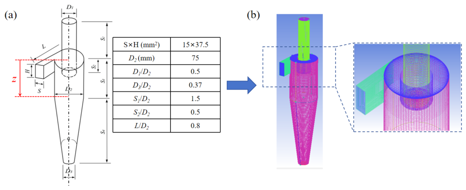
The swirling section of a Hydro-jet Cyclone (HJC) with a nominal diameter of 75 mm was employed as the geometric model, as shown in Figure 1a. The inlet gas rate (Vg, m/s), column height (S3, mm), and cone angle (α, °) were selected as variables. Notably, the cone section length (S4) varied with α. As shown in Figure 1a, a longitudinal reference coordinate (Z, mm) was defined with the top of the cylindrical section as the origin. The computational domain was meshed using ANSYS-ICEM (2022 R1), as illustrated in Figure 1b, with a total mesh count of 757,251. Given the relatively regular geometry of the cyclone, hexahedral structured grids were adopted to better conform to the boundaries. Since droplet motion was concentrated near the wall region, boundary layer grids were refined adjacent to the cyclone wall, with eight layers and a growth factor of 1.15, to enhance the computational accuracy of the flow field near the wall and facilitate subsequent DPM analysis.
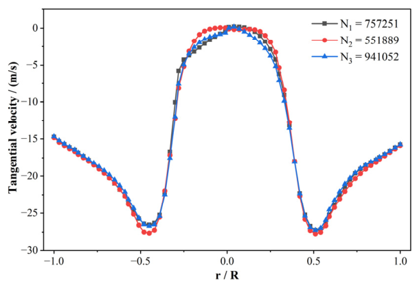
To eliminate the influence of mesh density on simulation accuracy, a mesh independence study was conducted using three structured grids with different cell counts, as follows: N1 = 757,251, N2 = 551,889, and N3 = 941,052 cells. The tangential velocity distribution at Z = 50 mm was selected as the criterion for mesh independence, since particle self-rotation is primarily governed by tangential velocity gradients. As shown in Figure 2 (where R is the radius of the cyclone, and r is the distance from the selected point to the center of the cross-section), the three profiles agree well across the entire radial domain. Using N1 as the baseline, the average relative deviations are 1.94% (N2) and 1.36% (N3). Considering the excellent overall agreement, N1 (757,251 cells) was selected as the working mesh to balance accuracy and computational cost.

2.3. Boundary Conditions and Solution

To investigate the effects of swirling structure and inlet gas rate on droplet motion, simulations were conducted under varying inlet gas rates (Vg = 12, 17, 22 m/s), column heights (S3 = 75, 112.5, 150 mm), and cone angles (α = 6, 14, 18°). The baseline operating conditions were set as Vg = 12 m/s, S3 = 112.5 mm, and α = 14°. Simulated droplet particles (SDPs) were generated based on the Very Coarse spray quality droplets (500 μm) specified in the ASABE S572.1 standard [28].
The droplet volume fraction in the present system is about 2–5%, which places the flow in the dilute regime and satisfies the DPM applicability criterion (dispersed phase volume fraction < 10%). Under this condition, DPM can track individual droplets in a Lagrangian framework and provide trajectory, revolution, and self-rotation data. Other methods fall short. The VOF method captures interfaces but is too expensive for tracking many droplets over long times. The Eulerian-Eulerian approach treats both phases as continua and cannot give individual droplet information. For these reasons, DPM was used to simulate droplet motion characteristics, with SDPs injected near the inlet center using the INJECTION function and a density of 1150 kg/m3. The solution process was configured as a steady-state model. Pressure-velocity coupling was handled by the SIMPLEC algorithm, which offers broad applicability; pressure discretization was solved using the PRESTO! Scheme, and conservation equations were discretized using the QUICK scheme, ensuring enhanced congruence between simulation results and physical reality.

2.4. Modeling Verification

The geometric model adopted in this study is identical to the experimental work previously conducted by our team [21], in which alumina particles were used to experimentally validate the device for suspended deoiling. The structural parameters (including the nominal diameter, cone angle, column height, and inlet configuration) are consistent with the geometrically validated structure in the simulation in this study. The mesh resolution, boundary conditions, and turbulence model settings (RSM for the continuous phase) adopted in this study are consistent with the previously validated numerical simulations for this geometry [19]. Under the premise of maintaining identical numerical settings, only the simulated phase was replaced with 500-μm simulated droplet particles (SDPs) of different density. The reliability of the CFD-DPM framework is indirectly supported through structural and parametric consistency.

3. Results and Discussion

3.1. Trajectories of the SDPs

3.1.1. Effect of Inlet Gas Rate on Trajectories of SDPs

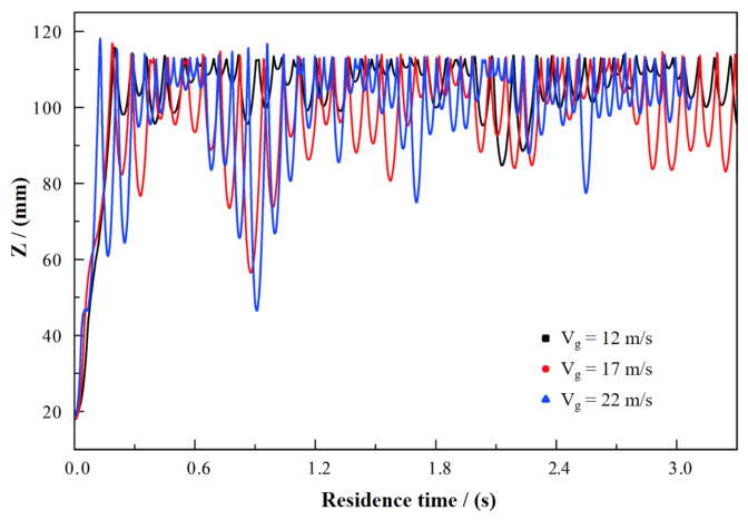
As shown in Figure 3, the relationship between SDPs residence time and their positions within the cyclone under varying inlet gas rates is presented, with the baseline operating conditions as the reference. It is important to note that the inlet gas rate here refers to the gas velocity at the tangential inlet, and its product with the tangential inlet area gives the volumetric flow rate of the gas. When the swirling structure remained consistent, SDPs primarily exhibited circulating motion within overlapping suspension zones, with specific trajectories varying with gas rate. At Vg = 12 m/s, SDPs stably circulated in the cylindrical section region of Z = 100–110 mm with relatively small fluctuation amplitudes. At Vg = 17 m/s, SDPs stably circulated in the cylindrical section region of Z = 80–115 mm, with fluctuation amplitudes expanding outward as gas rate increased. At Vg = 22 m/s, SDPs stably circulated in the cylinder-cone junction region of Z = 70–120 mm, with fluctuation amplitudes further increasing with gas rate. Therefore, within the swirling structure, SDPs exhibited a suspended rotation state, and the suspension zone demonstrated an expanding trend toward the overflow pipe direction with increasing gas rate.

3.1.2. Effect of Column Height on the Trajectory of SDPs

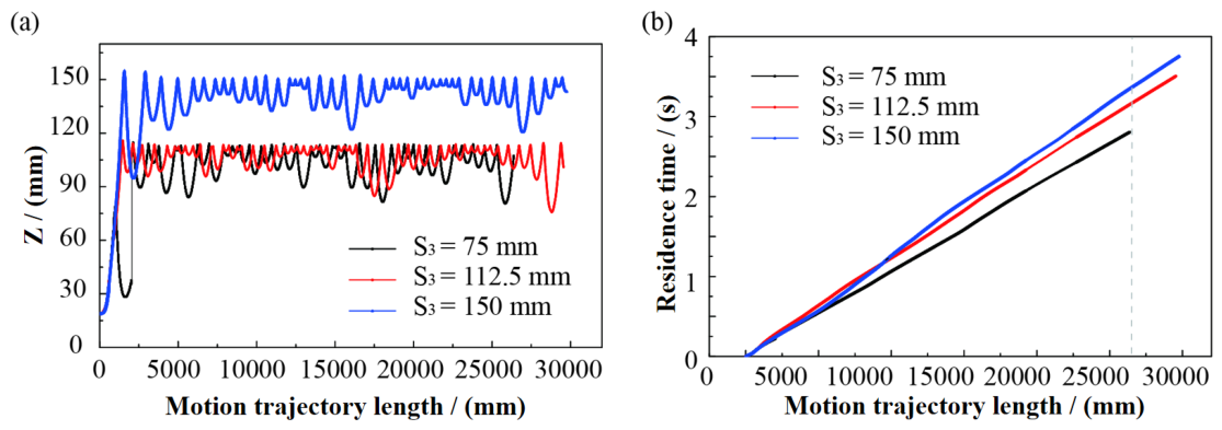
As shown in Figure 4a, the trajectories of SDPs within the cyclone under different column heights are presented. When the cone angle and inlet gas rate remained identical, SDPs exhibited suspended circulation following essentially the same pattern, with nearly unchanged fluctuation amplitudes; however, the suspension zone migrated downward with increasing column height. At S3 = 75 mm, SDPs stably circulated in the cylindrical section region of Z = 90–110 mm. At S3 = 112.5 mm, SDPs stably circulated in the cylinder-cone junction region of Z = 90–120 mm. At S3 = 150 mm, SDPs stably circulated in the cone section region of Z = 120–150 mm. For an equivalent residence time, shorter column heights resulted in longer SDPs trajectories, suggesting a broader motion range and more extensive interaction with the surrounding fluid. As shown in Figure 4b, for an equivalent trajectory length, increasing column height prolonged the residence time of SDPs within the cyclone, which facilitated sufficient contact between SDPs and the gas phase.

3.1.3. Effect of Cone Angles on the Trajectories of SDPs

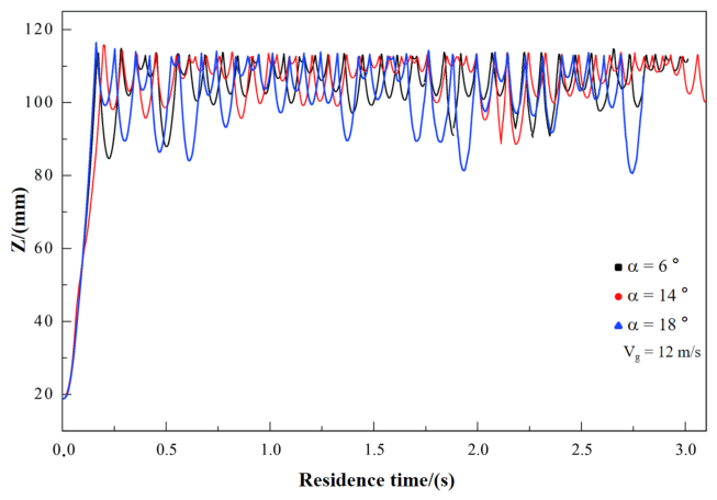
As shown in Figure 5, the relationship between SDPs residence time and their positions within the cyclone under different cone angles is presented. As illustrated, SDPs exhibited suspended circulation within the cyclone. At a cone angle of α = 6°, SDPs stably circulated in the cylindrical section region of Z = 100–110 mm. When the cone angle increased to α = 14°, the suspension zone correspondingly expanded to the cylinder-cone section region of Z = 100–120 mm. As the cone angle further increased to 18°, the suspension zone extended upward to the cylinder-cone region of Z = 80–120 mm.
With decreasing cone angle, the fluctuation amplitudes of SDPs in the swirling flow field diminished, and the suspension zone became more concentrated. Magnified analysis revealed that SDPs entered from the inlet center, spiraled downward to the cylinder-cone junction, and then returned to initiate recirculation, with gradually decreasing amplitudes. Over time, the motion basically exhibited an alternating pattern of large and small fluctuation amplitudes, and the fluctuation amplitudes of suspended rotation showed a positive correlation with the cone angle.

3.2. Revolution Speed of SDPs

3.2.1. Effect of Inlet Gas Rate on the Revolution Speed of SDPs

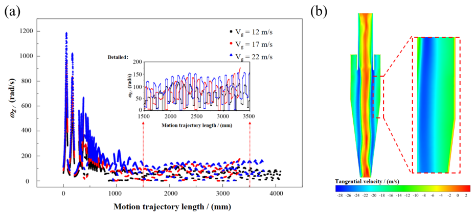
As shown in Figure 6a, the revolution speed of SDPs in the swirling flow field at a cone angle of 14° under different gas rate is presented, with the vertical axis representing the SDPs revolution speed, ωZ (rad/s). At an inlet gas rate of 12 m/s, the average revolution speed of SDPs was ωZ = 50 rad/s. At 17 m/s, the average revolution speed was ωZ = 60 rad/s. At 22 m/s, the revolution speed of SDPs in the swirling flow field fluctuated uniformly between 0 and 200 rad/s, with the average revolution speed increasing to 80 rad/s as the inlet gas rate increased.
Due to the turbulent characteristics of the swirling flow field, the revolution speed of SDPs exhibited a scattered fluctuation distribution along the motion trajectory. When the inlet gas rate increased, the revolution speed of SDPs increased significantly, with pronounced peaks observed near the inlet region. As SDPs migrated downstream, the suspended rotation region stabilized, and the revolution speed consequently stabilized within the corresponding range. The increase in inlet gas rate directly enhanced the energy of the swirling flow field, thereby imparting greater revolution speed to the SDPs. Moreover, the extremely thin boundary layer near the cyclone wall featured rapidly varying velocity gradients. Figure 6b shows the contour of tangential velocity in a longitudinal plane. A distinct high-velocity-gradient zone exists near the wall, where the tangential velocity changes sharply from the wall toward the center, indicating strong shear effects in this region. Thus, SDPs traversing swiftly through the boundary layer fluid exhibited sharp increases followed by rapid decreases in velocity, resulting in prominent peak characteristics.

3.2.2. Effect of Column Height on the Revolution Speed of SDPs

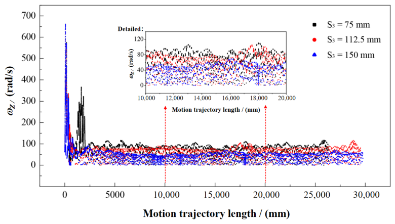
As shown in Figure 7, under the baseline condition of 12 m/s inlet gas rate and 14° cone angle, the revolution speed of suspended SDPs primarily fluctuated uniformly between 0 and 100 rad/s, with the average revolution speed decreasing as column height increased. Considering that the motion of SDPs in the cylindrical section represented an energy dissipation process without external energy input, a single-phase flow analysis further confirms that turbulent kinetic energy (k) is elevated near the inlet (k ≈ 0.188 m2/s2) and decays rapidly downstream (k ≈ 0.00023 m2/s2 near the bottom outlet), with the dissipation rate (ε) decreasing from 0.0573 m2/s3 to 0.00012 m2/s3 accordingly. Therefore, the energy of SDPs dissipated with increasing column height, resulting in a decreasing trend of revolution speed.
At a column height of S3 = 75 mm, the revolution speed of suspended SDPs stabilized in the range of 40–100 rad/s. At S3 = 112.5 mm, the revolution speed of suspended SDPs decayed and stabilized between 20 and 80 rad/s. When the column height further increased to 150 mm, additional energy loss occurred within the swirling flow field, and the maximum revolution speed of SDPs decreased to 40 rad/s.

3.2.3. Effect of the Cone Angle on the Revolution Speed of SDPs

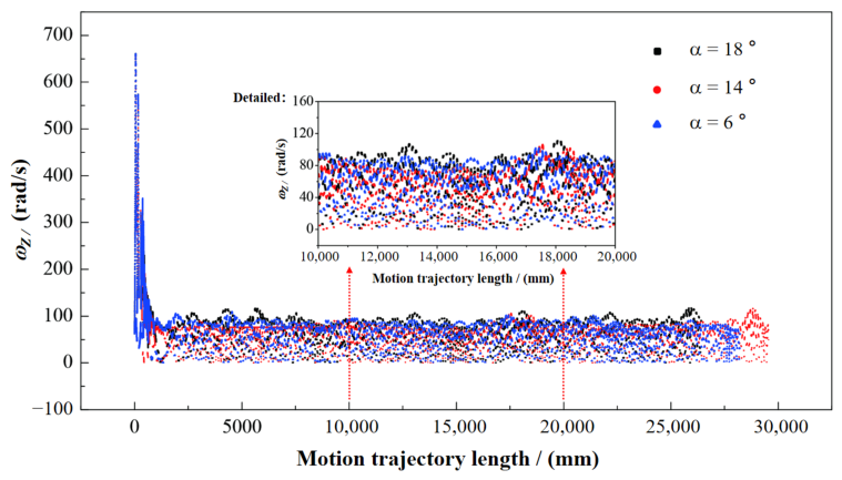
As shown in Figure 8, during the circulating motion of SDPs, when the column height remained constant, the energy within the swirling flow field was essentially conserved. At a fixed inlet gas rate and without external flow disturbance, the internal swirling flow field maintained a relatively stable state; consequently, the revolution speed of SDPs remained essentially unchanged. At an inlet gas rate of 12 m/s, the revolution speed of SDPs was maintained approximately between 0 and 100 rad/s, which was roughly consistent with that of SDPs in cyclones with different column heights at the same gas rate. However, with varying cone angles, the revolution speed exhibited negligible differences. Therefore, the revolution speed of SDPs in the swirling flow field was weakly influenced by the cyclone cone angle, while demonstrating a decreasing trend with increasing column height.

3.3. Self-Rotation Speed of SDPs

3.3.1. Effect of Inlet Gas Rate on the Self-Rotation Speed of SDPs

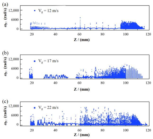
As shown in Figure 9, the self-rotation speed of SDPs under different inlet gas rates is presented, with the vertical axis representing the SDPs self-rotation speed, ωP (rad/s). At Vg = 12 m/s, the self-rotation speed of SDPs stabilized below 3500 rad/s, reaching a stable high-speed state in the suspension region near the cylinder-cone junction. At Vg = 17 m/s, the self-rotation speed of SDPs increased accordingly, achieving stable self-rotation below 6000 rad/s in the cylinder-cone region of Z = 80–120 mm. When the gas rate increased to 22 m/s, the self-rotation speed of SDPs further increased with the gas rate, with prominent peak characteristics, attaining a suspended high-speed self-rotation state below 12,000 rad/s over a broad range of Z = 60–120 mm.
After SDPs entered the cyclone through the tangential inlet, as shown in Figure 9, they initially underwent unstable motion with drastic velocity variations under the influence of boundary layer vortices, and subsequently stabilized into suspended rotation in the cylinder-cone region of the cyclone, with the self-rotation speed stabilizing in the corresponding zone. When the operating conditions remained unchanged, the suspension zone was maintained constant. According to the simulation results, the self-rotation of SDPs was generated by strong shear in the boundary layer, with the self-rotation speed equal to half of the tangential vorticity, as the self-rotation speed is related to the vorticity distribution [29]. When SDPs approached the wall, the fluid shear force intensified, resulting in greater self-rotation speed of SDPs.
Since higher inlet gas rates corresponded to stronger fluid shear intensity and increased fluid tangential velocity, the self-rotation speed of SDPs rose accordingly, conferring greater motility to SDPs within the swirling flow field. Due to the large tangential velocity gradients and extremely strong shear flow surrounding the boundary layer, irregular peak characteristics of self-rotation speed emerged when SDPs were near the wall. As the inlet gas rate was linearly correlated with fluid tangential velocity, and the self-rotation speed of SDPs was significantly affected by flow rate variations, the shear intensity of the tangential fluid exerted a substantial influence on the self-rotation speed of SDPs, whereas the effects of axial and radial fluids were negligible and could be disregarded.

3.3.2. Effect of Column Height on the Self-Rotation Speed of SDPs

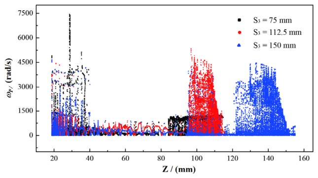
As shown in Figure 10, the self-rotation speed of SDPs under different column heights is presented. As illustrated, column height exerted a significant influence on the self-rotation speed of SDPs; however, since the length of the cylindrical section affected the suspension zone of SDPs, the position where SDPs achieved stable suspended self-rotation varied with column height. When SDPs entered through the tangential inlet, the boundary layer effect caused a sharp increase in self-rotation speed; the extremely thin boundary layer led to a drastic decrease in self-rotation speed after SDPs rapidly traversed the near-wall region. As shown in the figure, at a gas rate of 12 m/s, SDPs exhibited a peak self-rotation speed of up to 4500 rad/s upon initial entry into the cyclone; after penetrating the boundary layer, the self-rotation speed rapidly decreased and was maintained in the range of 0–700 rad/s. When SDPs entered the stable suspended rotation region in the cylinder-cone zone, the self-rotation speed increased and sustained a high-speed self-rotation state.
At S3 = 75 mm, due to the relatively short column height, SDPs escaped after a certain rotation period, resulting in an interruption of self-rotation speed. At S3 = 112.5 mm, SDPs achieved high-speed self-rotation below 4500 rad/s in the stable suspended rotation region. At S3 = 150 mm, the suspension zone of SDPs migrated downward with increasing column height, while the self-rotation speed remained essentially unchanged. In the swirling cone section, the swirling radius continuously contracted, replenishing the energy dissipation of SDPs and maintaining their tangential velocity at a relatively stable level; consequently, SDPs realized stable suspended high-speed self-rotation in the cylinder-cone junction region.

3.3.3. Effect of Cone Angle on the Self-Rotation Speed of SDPs

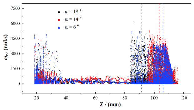
The self-rotation speed of SDPs under different cone angles is shown in Figure 11. Similar to the self-rotation behavior observed in the column height comparison group, SDPs exhibited extremely high self-rotation speed upon initial entry due to the large vorticity near the wall; as SDPs migrated toward the cyclone center, the self-rotation speed rapidly decreased and was maintained between 0 and 700 rad/s. After reaching a stable suspended rotation state, the self-rotation speed of SDPs increased and remained at a relatively high level. Unlike the column height variation, the self-rotation speed of SDPs demonstrated a weakening trend with decreasing cone angle; moreover, larger cone angles shifted the peak self-rotation position progressively upward toward the cylindrical section above the cylinder-cone junction.
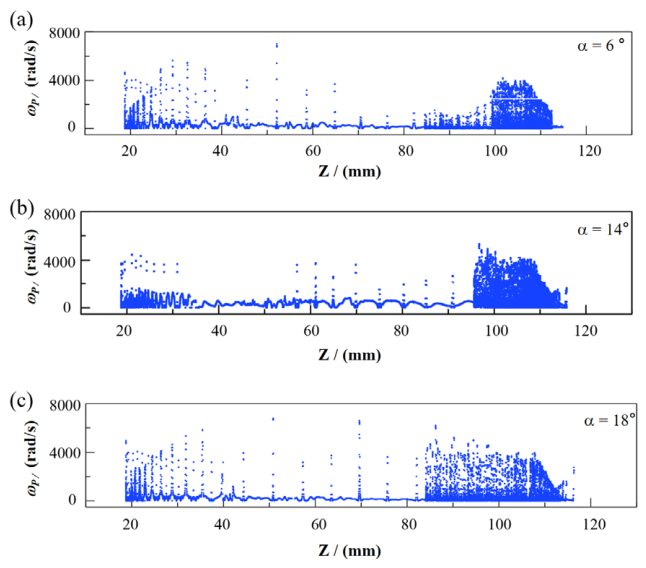
A split detailed analysis of SDPs self-rotation speed under different cone angles is presented in Figure 12. At the inlet position of Z = 20–40 mm, the self-rotation speed of SDPs exhibited drastic fluctuations, showing peak characteristics of approximately 4000 rad/s. Considering the intense turbulence variation in the boundary layer, the motion of SDPs at the inlet was relatively fluctuating. When SDPs swirled to the cylinder-cone junction position of Z = 80–120 mm, their motion tended to stabilize; the trajectories no longer varied but rather circulated repeatedly in the cylinder-cone section, and the self-rotation speed of SDPs reached relatively high levels. As the cone angle of the swirling flow field continuously increased, the self-rotation speed of SDPs rose accordingly, and SDPs transitioned from partially stable high-speed suspension to fully stable high-speed suspension.
With increasing cone angle, the self-rotation speed of SDPs demonstrated an increasing trend; however, the effect of cone angle on SDPs self-rotation speed was weaker than that of gas rate. This may be attributed to the fact that the analysis focused primarily on the cylindrical section, whereas the cone angle mainly altered the gas flow in the cone section; the changes in the lower cylindrical section position resulted primarily from the motion variation in the internal separation air column induced by cone angle changes. With larger cone angles, SDPs possessed greater energy, the high-speed suspension region of SDPs expanded, and peak characteristics became more pronounced. Through adjustment of structural parameters and inlet gas rate, the suspension zone and self-rotation speed during stable suspension of SDPs could be regulated, which is of significant importance for controlling SDPs motion in turbulent flow fields.

4. Conclusions

In this study, the swirling section of a Hydro-jet Cyclone (HJC) with a nominal diameter of 75 mm served as the geometric model. Using the Computational Fluid Dynamics-Discrete Phase Model (CFD-DPM), systematic numerical simulations were conducted on the macroscopic motion behaviors of 500-μm simulated droplet particles (SDPs) in swirling flow fields, with particular emphasis on the effects of inlet gas rate, column height, and cone angle on trajectories, revolution speed, and self-rotation speed. The main conclusions are as follows:
(1)
Rather than spiraling downward along the wall or undergoing short-circuit escape, SDPs primarily exhibited suspended circulation within the cyclone. The location and extent of the suspension zone were synergistically governed by structural and operating parameters, as follows: the zone expanded and shifted toward the overflow pipe with increasing inlet gas rate (12–22 m/s) and cone angle (6–18°), while migrating downward with increasing column height (75–150 mm). Among these factors, column height dominated the regulation of suspension position.
(2)
The revolution speed of SDPs was primarily governed by inlet gas rate and column height, while exhibiting negligible sensitivity to cone angle variations. As inlet gas rate increased from 12 m/s to 22 m/s, the average revolution speed rose from approximately 50 rad/s to 80 rad/s, indicating that energy input from the swirling flow field served as the dominant driver of revolution. However, the motion of SDPs within the cylindrical section constituted an energy dissipation process without external energy supplementation; consequently, turbulence energy dissipation caused the revolution speed to progressively decay with increasing column height (40–100 rad/s at 75 mm, and a maximum of 40 rad/s at 150 mm). Variations in cone angle exerted minimal influence on the total energy of the swirling flow field, and thus had virtually no effect on revolution speed.
(3)
The self-rotation speed of SDPs was driven by strong near-wall boundary layer shear, equal to half of the local tangential vorticity. An instantaneous peak of 4500 rad/s occurred at the inlet due to the extremely thin boundary layer, followed by a rapid drop to 0–700 rad/s and subsequent recovery to high-speed self-rotation near the cylinder-cone junction. Inlet gas rate dominated the stable self-rotation speed, increasing it from below 3500 rad/s at 12 m/s to 12,000 rad/s at 22 m/s. Cone angle exerted a secondary promoting effect by expanding the high-speed suspension zone, while column height mainly influenced self-rotation indirectly through suspension zone migration.
This study revealed the core dynamic mechanism of “suspension-migration-energy dissipation-boundary-layer shear-driven self-rotation” governing droplets in HJC swirling flow fields, and clarified the differentiated roles of inlet gas rate, column height, and cone angle in regulating droplet motion. The findings furnish a numerical reference for the quantitative understanding of droplet dynamic behaviors in HJC gas–liquid systems, and establish a simulation framework and data foundation for subsequent research on coupled mass transfer-separation processes and cyclone structural optimization.
That said, this study has several limitations. The SDP approach uses rigid spheres to represent real droplets, so it cannot capture deformation, breakup, coalescence, or interfacial mass transfer. Here we focus on macroscopic motion behaviors (trajectory, revolution, self-rotation) governed by large-scale flow structures; treating droplets as rigid particles is a pragmatic starting point for understanding dispersed-phase dynamics in HJC swirling flows. A second limitation is that only one droplet size (500 μm) was examined. Real HJC systems handle droplets with a wide size distribution, so polydisperse effects are left for future work. Finally, all results come from numerical simulations without experimental validation, which constrains the quantitative reliability of the predicted absolute values. Subsequent work can extend the present framework to coupled VOF-DPM or fully resolved simulations that include droplet deformation and polydispersity, and can be supplemented by experimental measurements (high-speed imaging, phase-Doppler anemometry).

Author Contributions

Conceptualization, Y.Z., Y.Y., Z.-B.Z., B.-S.G. and L.-W.W.; methodology, Y.Z., Z.-H.Y., Y.Y. and Z.-B.Z.; software, Y.Y., Y.-L.C.; validation, Y.-L.C., B.-S.G. and L.-W.W.; formal analysis, Y.Z., Y.Y. and Z.-B.Z.; investigation, Y.Y., Z.-B.Z.; resources, Y.-L.C., B.-S.G.; data curation, Y.Y., L.-W.W.; writing—original draft preparation, Y.Z., L.-W.W.; writing—review and editing, Y.Z., Z.-H.Y.; visualization, B.-S.G.; supervision, Y.-L.C.; project administration, B.-S.G.; funding acquisition, Y.-L.C., B.-S.G. All authors have read and agreed to the published version of the manuscript.

Funding

This research received no external funding.

Data Availability Statement

The original contributions presented in this study are included in the article. Further inquiries can be directed to the corresponding author.

Conflicts of Interest

Authors Yong Yu, Zhi-Bin Zhou, and Ben-Shuai Guo were employed by the Sinopec Nanjing Chemical Industries Co., Ltd. The remaining authors declare that the research was conducted in the absence of any commercial or financial relationships that could be construed as a potential conflict of interest.

References

  1. Liu, B.; Ma, H.; Huang, Q.; Chen, J.; Huang, Y.; Huang, H.; Wei, Q.; Wang, H.; Lv, W. Internal reuse of methanol-to-olefin wastewater based on micro-channel separation coupling hydrocyclone regeneration. J. Environ. Manag. 2023, 345, 118791. [Google Scholar] [CrossRef] [PubMed]
  2. Zheng, J.; Du, J.; Huang, Y.; Zhao, J.; Wu, J.; Zhang, Y.; Wang, H. Cementation breaking and grit separation characteristics of weakly cemented natural gas hydrate by a new structure hydrocyclone. Appl. Energy 2024, 361, 122913. [Google Scholar] [CrossRef]
  3. Jing, J.; Zhang, S.; Qin, M.; Luo, J.; Shan, Y.; Cheng, Y.; Tan, J. Numerical simulation study of offshore heavy oil desanding by hydrocyclones. Sep. Purif. Technol. 2021, 258, 118051. [Google Scholar] [CrossRef]
  4. Guo, M.; Yang, L.; Son, H.; Le, D.K.; Manickam, S.; Sun, X.; Yoon, J.Y. An overview of novel geometrical modifications and optimizations of gas-particle cyclone separators. Sep. Purif. Technol. 2024, 329, 125136. [Google Scholar] [CrossRef]
  5. Dong, J.; Chen, G.; Zhang, P.; Li, J. Separation Performance Enhancement of Gas-Solid Cyclone Separators by Flow Control and Coupling Physical Fields. Sep. Purif. Rev. 2026, 55, 109–124. [Google Scholar] [CrossRef]
  6. Yang, Q.; Wang, H.-L.; Liu, Y.; Li, Z.-M. Solid/liquid separation performance of hydrocyclones with different cone combinations. Sep. Purif. Technol. 2010, 74, 271–279. [Google Scholar] [CrossRef]
  7. Zhang, Y.; Yang, Z.-H.; Chang, Y.-L.; Li, J.-P.; Wang, B.-D.; Jin, Z.-H.; Ma, L.; Jiang, X.; Wang, H.-L. In-situ reactivation of the catalyst for hydrodeoxygenation of bio-oil to biofuel by coupling the self-rotation and revolution of catalysts in the swirling flow. J. Clean. Prod. 2026, 553, 148012. [Google Scholar] [CrossRef]
  8. Wang, L.; Wang, H.; Ma, L.; Yang, Z.; Chen, E. Gas cyclone-liquid jet absorption separator used for treatment of tail gas containing HCl in titanium dioxide industry. Chin. J. Chem. Eng. 2022, 44, 435–446. [Google Scholar] [CrossRef]
  9. Wang, L.; Chen, E.; Ma, L.; Yang, Z.; Li, Z.; Yang, W.; Wang, H.; Chang, Y. Numerical simulation and experimental study of gas cyclone-liquid jet separator for fine particle separation. Chin. J. Chem. Eng. 2022, 51, 43–52. [Google Scholar] [CrossRef]
  10. Duan, X.; Cong, C.; Wang, L.; Liu, Y.; Zhao, Z.; Wu, J.; Ma, L. Spontaneous supergravity field drives liquid-phase microelements to enhance CO2 capture through self revolution coupling. Sep. Purif. Technol. 2025, 360, 131058. [Google Scholar] [CrossRef]
  11. Hirt, C.W.; Nichols, B.D. Volume of fluid (VOF) method for the dynamics of free boundaries. J. Comput. Phys. 1981, 39, 201–225. [Google Scholar] [CrossRef]
  12. Sussman, M.; Puckett, E.G. A Coupled Level Set and Volume-of-Fluid Method for Computing 3D and Axisymmetric Incompressible Two-Phase Flows. J. Comput. Phys. 2000, 162, 301–337. [Google Scholar] [CrossRef]
  13. Tropea, C.; Yarin, A.L.; Foss, J.F. Springer Handbook of Experimental Fluid Mechanics; Springer: London, UK, 2007; Volume 1. [Google Scholar]
  14. Deen, N.G.; Westerweel, J.; Delnoij, E. Two-Phase PIV in Bubbly Flows: Status and Trends. Chem. Eng. Technol. 2002, 25, 97–101. [Google Scholar] [CrossRef]
  15. Poelma, C.; Westerweel, J.; Ooms, G. Turbulence statistics from optical whole-field measurements in particle-laden turbulence. Exp. Fluids 2006, 40, 347–363. [Google Scholar]
  16. de Motta, J.B.; Costa, P.; Derksen, J.J.; Peng, C.; Wang, L.-P.; Breugem, W.-P.; Estivalèzes, J.-L.; Vincent, S.; Climent, E.; Fede, P. Assessment of numerical methods for fully resolved simulations of particle-laden turbulent flows. Comput. Fluids 2019, 179, 1–14. [Google Scholar] [CrossRef]
  17. Chu, K.W.; Wang, B.; Xu, D.L.; Chen, Y.X.; Yu, A.B. CFD-DEM simulation of the gas-solid flow in a cyclone separator. Chem. Eng. Sci. 2011, 66, 834–847. [Google Scholar] [CrossRef]
  18. Nakhaei, M.; Lu, B.; Tian, Y.; Wang, W.; Dam-Johansen, K.; Wu, H. CFD Modeling of Gas-Solid Cyclone Separators at Ambient and Elevated Temperatures. Processes 2020, 8, 228. [Google Scholar]
  19. Fu, P.; Zhu, J.; Li, Q.; Cheng, T.; Zhang, F.; Huang, Y.; Ma, L.; Xiu, G.; Wang, H. DPM simulation of particle revolution and high-speed self-rotation in different pre-self-rotation cyclones. Powder Technol. 2021, 394, 290–299. [Google Scholar] [CrossRef]
  20. Huang, Y.; Li, J.-P.; Zhang, Y.-H.; Wang, H.-L. High-speed particle rotation for coating oil removal by hydrocyclone. Sep. Purif. Technol. 2017, 177, 263–271. [Google Scholar] [CrossRef]
  21. Shi, D.; Huang, Y.; Wang, H.; Yuan, W.; Fu, P. Deoiling of oil-coated catalyst using high-speed suspending self-rotation in cyclone. Sep. Purif. Technol. 2019, 210, 117–124. [Google Scholar] [CrossRef]
  22. Cheng, T.; Li, Q.; Wang, H.; Fang, X.; Li, L.; Jiang, L.; Li, J.; Huang, Y.; Yang, T.; Fu, P. High-speed particle self-rotation in different pre-self-rotation cyclones and application in enhancement of oil recovery from spent catalysts. Sep. Purif. Technol. 2022, 296, 121430. [Google Scholar] [CrossRef]
  23. Liu, T.; Heng, Y.; Jiang, Q.; Chen, Z.; Luo, X. Numerical simulation study of particle self-rotation velocity in cyclone separator. J. Phys. Conf. Ser. 2024, 2707, 012159. [Google Scholar] [CrossRef]
  24. Zhao, J.; Hao, X.; Guo, X.; Gao, F.; Fan, J.; Zhang, P.; Chen, G. Effect of local erosion on flow pattern and particle self-rotation in a cyclone separator. Adv. Powder Technol. 2025, 36, 104949. [Google Scholar] [CrossRef]
  25. Huang, Y.; Wang, H.-L.; Tian, J.; Li, J.; Fu, P.; He, F. Theoretical study on centrifugal coupling characteristics of self-rotation and revolution of particles in hydrocyclones. Sep. Purif. Technol. 2020, 244, 116552. [Google Scholar] [CrossRef]
  26. Zhang, X.; Wu, H.; Ma, S.; Ma, L.; Wang, K.; Wang, H.; Jiang, X.; Chang, Y. Flash drying of slurry-liquid sewage sludge based on avoidance of latent heat of phase change: Laboratory to pilot-scale evolution. Chem. Eng. J. 2024, 480, 148371. [Google Scholar] [CrossRef]
  27. Launder, B.E.; Reece, G.J.; Rodi, W. Progress in the development of a Reynolds-stress turbulence closure. J. Fluid Mech. 1975, 68, 537–566. [Google Scholar] [CrossRef]
  28. ASABE S572.1; Droplet Size Classification. ASABE: St. Joseph, MI, USA, 2009.
  29. Frish, M.B.; Webb, W.W. Direct measurement of vorticity by optical probe. J. Fluid Mech. 1981, 107, 173–200. [Google Scholar] [CrossRef]
Figure 1. (a) Structure of cyclone and (b) meshing diagram.
Separations 13 00192 g001
Figure 2. Mesh independence verification.
Separations 13 00192 g002
Figure 3. SDPs positions and residence time under different inlet gas rates.
Separations 13 00192 g003
Figure 4. SDPs (a) positions and (b) residence time under different column heights.
Separations 13 00192 g004
Figure 5. Residence time and positions of SDPs under different cone angles.
Separations 13 00192 g005
Figure 6. (a) Revolution speed of SDPs under different inlet gas rates; (b) tangential velocity distribution.
Separations 13 00192 g006
Figure 7. Revolution speed of SDPs under different column heights.
Separations 13 00192 g007
Figure 8. Revolution speed of SDPs under different cone angles.
Separations 13 00192 g008
Figure 9. Self-rotation speed of SDPs under different gas inlet gas rates:(a) 12 m/s, (b) 17 m/s, and (c) 22 m/s.
Separations 13 00192 g009
Figure 10. Self-rotation speed of SDPs under different column heights.
Separations 13 00192 g010
Figure 11. The influence of cone angle on SDPs self-rotation speed.
Separations 13 00192 g011
Figure 12. Split diagram of self-rotation speed of SDPs under different cone angles: (a) 6°, (b) 14°, and (c) 18°.
Separations 13 00192 g012
Disclaimer/Publisher’s Note: The statements, opinions and data contained in all publications are solely those of the individual author(s) and contributor(s) and not of MDPI and/or the editor(s). MDPI and/or the editor(s) disclaim responsibility for any injury to people or property resulting from any ideas, methods, instructions or products referred to in the content.