Abstract
We investigate band broadening in the most widely adopted configuration of micro-pillar array columns (PACs)—specifically, a cylindrical pillar array where both the pillar walls and the channel bottom are coated with a thin layer of mesoporous material. The two-zone moment analysis method is adopted to investigate the dispersion properties of PACs in a broad range of shell thicknesses, reduced fluid velocities, and retention factors. Three different models of the unit cell, of increasing complexity, have been implemented, namely a two-dimensional model and two different three-dimensional models with and without the retentive bottom layer, the presence of which seems to have a very significant effect on the plate height curves. Model predictions are compared with experimental van Deemter curves for uncoated and coated porous layers, and a robust relationship between the intra-particle (porous-zone) diffusion coefficient and the retention factor is established.
1. Introduction
A comprehensive grasp of the mechanisms causing band broadening in liquid chromatography is vital for advancing HPLC column technology and optimizing the speed of liquid chromatography procedures [1,2,3,4,5]. In the last two decades, research in liquid chromatography (LC) has prioritized the development of novel columns, aiming to significantly enhance packing uniformity [6,7,8,9,10,11,12,13] well beyond the capabilities of current packed-bed and monolithic silica columns. The advances in this realm have led to the creation of innovative LC columns through the in situ etching of a 2-D array of micromachined pillars. This process employs a lithographic mask to precisely define the position and dimensions of the pillars [9,14,15,16,17,18,19]. In the case of non-porous pillars, e.g., COMOSS columns, the adsorption surface is too limited to compete with packed-bed columns. To address this issue, porous-shell pillars have been introduced, achieved through electrochemical anodization of solid silicon pillars obtained via deep reactive ion etching [20,21]. The retention surface area of porous pillars is 250 to 500 times greater than that of non-porous pillars, and this factor can be further enhanced by increasing the shell thickness, with the goal of achieving the same level of loadability with PACs as with porous-shell particle columns [19].
These modern micro-pillar array columns (PACs) exemplify porous media with a hierarchical pore structure characterized by large inter-pillar macropores and small intra-pillar micropores. They offer the dual benefits of an organized macro-porous structure and a large surface area for microscale adsorption–desorption processes. The regular and ordered macro-pore network allows for the identification of a unit periodic cell as the fundamental representative element of the entire column.
Despite their simple geometry, PACs exhibit a fundamental distinction from open-tubular columns. While the latter geometry remains axially invariant, allowing the solution of the advection–diffusion equation governing its band broadening through the Aris method, the PAC geometry is spatially periodic. Consequently, it necessitates the application of more complex homogenization approaches [22,23,24,25,26,27,28,29,30] that can handle and exploit the periodic structure of the unit cell. Recently, a new homogenization approach, named two-zone moment analysis (TZMA), has been proposed and rigorously validated [31,32,33,34,35,36], for application in chromatographic systems. The TZMA approach is a novel homogenization strategy, alternative to volume averaging techniques [37,38,39,40,41], aimed at significantly enhancing the speed and precision in addressing the general advection–diffusion equation within hierarchical porous media featuring diffusion and adsorption–desorption processes. This robust and efficient moment-based method enables the precise computation of both local and integral concentration moments, thereby yielding exact solutions for the effective velocity and dispersion tensor of migrating solute particles. Notably, the method not only provides the exact effective transport parameters in the long-term asymptotic solution but also captures their complete transient behavior.
In this article, the TZMA method is adopted to investigate the dispersion properties of PACs in a broad range of shell thicknesses, reduced fluid velocities (Peclet numbers), and retention factors . Three different models of the unit cell, of increasing complexity, have been investigated. A two-dimensional model that does not take into account the height of the pillars; a three-dimensional model that takes into account the effect of the top and bottom walls on the velocity field and thus on the dispersion properties; and, finally, a three-dimensional model that accounts for the fact that not only the outer shell of the pillars is covered with a mesoporous layer, but also the surface at the bottom of the inter-pillar space, and this significantly affects the plate height curves. Model predictions are compared with experimental van Deemter curves for coumarine C480 in different water–methanol compositions from de Malsche at al. [21], and a robust relationship between the intraparticle (porous-zone) diffusion coefficient and the retention factor is established.
2. Materials and Methods
The geometry of the PAC unit periodic cell is reported in Figure 1. It perfectly matches the structure of the microchannel experimentally realized by de Malsche at al. [21], filled with an array of cylindrical pillars (diameter , height ) arranged on an equilateral triangular grid (external porosity ).
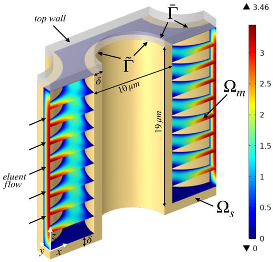
Figure 1.
Geometry of the unit cell of the PAC investigated. The yellow region is the stationary phase . Colored slices indicate the intensity of the normalized eluent velocity field in the mobile phase .
The anodization method adopted to obtain a porous layer of thickness on the lateral surface of the pillars cannot prevent the formation of a porous layer also on the bottom substrate as well. For this reason, Figure 1 shows the presence of the stationary phase of thickness (highlighted in yellow color) on both the sidewall of the pillars and the bottom wall. The top Pyrex wall is not affected by the anodization process because it is applied at the end of the process to seal the channel. The duration of the anodization process controls the thickness of the porous layer . Three different thicknesses are considered, namely . Before the coating procedure, the internal porosity is estimated as . It significantly reduces to after coating. The retentive capacity of coumarine C480 in the stationary phase can be modulated by changing the eluent (water–methanol) composition. Six different retention factors are considered, i.e., (no retention, before coating) and .
The TZMA method is adopted to estimate the dispersion coefficient along the eluent main flow direction x. The method, described in detail in [33], requires the solution of two steady-state transport equations for the b-fields and , defined in the mobile and stationary domains, respectively. The transport equations and boundary conditions for and , by assuming negligible mass-transfer resistance at the interface between the mobile and stationary phase, read as
where is the inner surface of the porous-shell layer, is the fluent velocity field, is its x component, is the effective longitudinal velocity, is the vector normal to (pointing from the mobile to the stationary phase), and is the vector normal to (pointing outwards the stationary phase). is the analyte diffusion coefficient in the mobile phase, and is the effective diffusion coefficient in the stationary phase, accounting for both hindered diffusion and adsorption of the analyte in the micro-porous phase, where any fluid motion is suppressed. Numerical details on the solution of the transport scheme Equations (1)–(5) are reported in Appendix A. The reader is referred to [33] for a detailed derivation of the b-field equations from the zeroth and first-order moments of the normalized analyte concentration satisfying the general rate model for chromatography [2,41,42]. The b-fields, so named after Brenner [23], represent the time-independent part of the first-order local moments, and their spatial gradients control the intensity of the dispersion tensor.
The effective longitudinal velocity is given by
in perfect agreement with the well-established result [42] that implies that equals the averaged interstitial longitudinal fluid velocity multiplied by the fraction of solute particles in the mobile phase . In Equation (6), is the volume of the mobile phase, and is the zone retention factor, related to the phase retention factor by the relationship
where is the zone retention factor of an unretained component that is greater than zero because also not-retained species undergo a slowdown when entering the micro-porous phase. For example, for coumarine C480, the measured values of before coating are for , respectively. After coating, as the internal porosity decreases from 0.73 to 0.6, the -values decreases to for , respectively.
From the b-fields, the longitudinal dispersion coefficient can be estimated in a straightforward way as
where the symbols and indicate the spatial average over the mobile and stationary domains, respectively. Once and are estimated, the dimensionless plate height h can be evaluated as
and the van Deemter curves are obtained, for a given (or ), by letting the Peclet value vary in the range of interest . Equations (6) and (8) clearly show that asymptotic dispersion properties and are directly derived from the steady-state equations governing the b-fields on the unit cell. This implies that the TZMA approach, not only allows solving the transport equations exclusively on a unit cell, but also eliminates the need to solve the time-dependent advection–diffusion equation from to a sufficiently large final time, thus involving a large number N of unit cells ( for the PACs), as required in DNS methods to ensure that asymptotic conditions are reached. This substantial reduction in computational efforts (approximately by a factor of ) enables a noteworthy enhancement in result accuracy, achieved by allowing the solution of b-fields transport equations on a denser and more detailed mesh grid. This level of reliability and accuracy of numerical results is unattainable with DNS techniques with affordable computational resources, particularly when dealing with three-dimensional problems, like that encountered for modeling PACS.
3. Results
The analysis of the PAC described in Section 2 can be performed, via the TZMA method, at three different levels of increasing complexity. In a two-dimensional approach to the problem, the unit cell is a 2-D cell obtained by cutting the three-dimensional domain with a plane positioned at half height . Therefore, the velocity field has only two components and is not affected by the presence of the upper and lower walls. In a three-dimensional approach, such as that implemented by Yan et al. [41], the entire three-dimensional cell is considered, and the velocity field , equipped with all components, is affected by the presence of the upper and lower walls, which result in vertical velocity gradients that give a significant contribution to dispersion. Overlooked, however, is the fact that the lower wall is also porous and therefore has adsorptive/retentive capabilities. The effect of the retentive lower wall, which is taken into account in a three-dimensional approach more faithful to the experimentally realized channel, is not negligible for the purpose of characterizing the longitudinal dispersion coefficient. The aim of Section 3.1 is to investigate the differences between the three cases described above, namely the 2-D, the 3-D, and the 3-D with retentive bottom (3-D rb) in terms of plate height curves in a wide range of zone retention factor and porous-zone diffusivity . In Section 3.2, the TMZA method is applied directly to the analysis of experimental plate height curves. The comparison between simulation results and experimental data leads to the estimate of the porous-zone diffusion coefficient , whose value is strongly dependent on the model adopted (2-D, 3-D, or 3-D rb).
3.1. Comparison between 2-D, 3-D, and 3-D rb Cases
Figure 2 and Figure 3 show the plate height curves h vs. for the same porous-layer thickness , three different values of and three different values of the zone retention factor, . Figure 2 shows the comparison between 2-D and 3-D results, while Figure 3 is the comparison between 3-D and 3-D rb plate height curves. The effect of the vertical variation of the velocity field, absent in the 2-D case, determines an increase in the 3-D plate height curve. This effect is appreciable for all values of and , but is more pronounced for lower values of and . An even more significant increase in the plate height curves is observed when comparing 3-D and 3-D rb results. The presence of the bottom retentive wall results in a further elevation of the h vs. curves, the more significant the higher and the lower the . This result is very easily explained if we consider that the longitudinal dispersion coefficient is larger, the higher the b-field gradients. In particular, the vertical component of the gradient of is amplified by the variation of the velocity field along z, while the vertical component of the gradient of is amplified by the presence of the lower wall when its retentive capacity is taken into account. The latter effect is more significant the lower the diffusivity in the porous zone and the higher , that is, the greater the fraction of solute particles in the stationary phase.
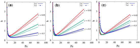
Figure 2.
Comparison between 2-D and 3-D dimensionless plate height curves h vs. for the same porous-layer thickness and for three different values of : (a) ; (b) ; (c) .
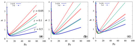
Figure 3.
Comparison between 3-D and 3-D rb dimensionless plate height curves h vs. for the same porous-layer thickness and for three different values of : (a) ; (b) ; (c) .
3.2. Analysis of Experimental Plate Height Curves
Based on the considerations made in Section 3.1, it is evident that the three different cases analyzed, when applied to the analysis of the experimental data reported by de Malsche et al. [21], will result in different values of the rescaled porous-zone diffusivity , which is the only parameter to be determined.
We preliminary analyze plate height curves determined for C480 before coating, i.e., without retention , . This allows us to determine the rescaled porous-zone diffusivity , which represents the obstruction factor in the stationary phase (stagnant mobile phase), because, in the absence of retention, is a direct measure of the hindered diffusion of the analyte in the porous zone.
Figure 4 shows the comparison between model predictions and experimental data for h vs. in the uncoated case for three different porous-shell thicknesses . The behavior of the theoretical curves is the same for the three models 2-D, 3-D, and 3-D rb.
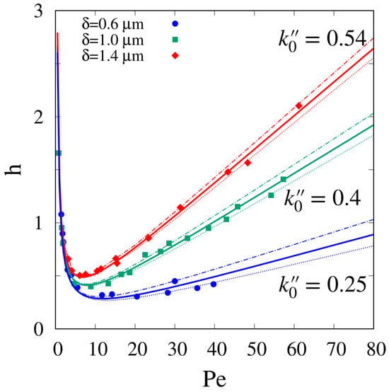
Figure 4.
Comparison between model predictions and experimental data for h vs. for C480 in the non-retentive case. Different curves correspond to different values of the porous-shell thickness . Best-fit values of values of are shown in Figure 5. Continuous, dashed and dot-dashed lines indicates the predictions with , , , reported as points with error-bars in Figure 5.
What changes significantly is the best-fit value of as reported in Figure 5 for the three models.
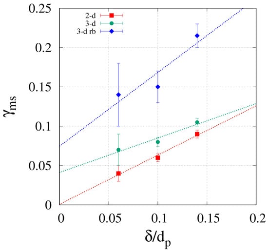
Figure 5.
Obstruction factor vs. for the three models, 2-D, 3-D, and 3-D rb.
It can be readily observed that, for all three models, the obstruction factor increases with the shell thickness. However, both the 2-D and the 3-D models significantly underestimate the obstruction factor with respect to the 3-D rb model, accounting for the bottom retentive layer. The values of estimated from the 3-D model are in agreement with results reported by Yan et al. [41], who analyzed exactly the same experimental data without considering the bottom retentive layer. From now on, we will consider exclusively the 3-D and 3-D rb models to further investigate the dependency of the porous-zone diffusivity on phase retention factor .
Figure 6 shows experimental plate height data h vs. for and different increasing values of .
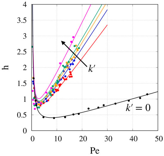
Figure 6.
Comparison between model predictions and experimental data for h vs. for C480 in the retentive case, . Different curves correspond to different values of the phase retention factor . Best-fit values of values of are shown in Figure 7.
Continuous lines show the predictions of the 3-D model with best-fit values of reported in Figure 7.
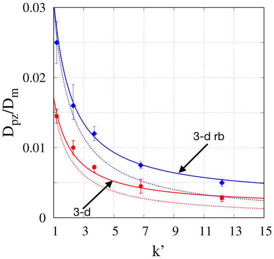
Figure 7.
Comparison between model predictions of and Equation (11) for , for the 3-D model, for the 3-D rb model. Dashed lines: . Continuous lines: for the 3-D and the 3-D rb models, respectively.
As expected, also in this retentive case, the 3-D model underestimates the porous-zone diffusivity with respect to the 3-D rb model. For both models, a similar decay of as a function of is observed, consistent with the general residence time-weighted expression for [43]
that can be equivalently rewritten in term of the phase retention factor as
where is the effective diffusion coefficient in the retained state (surface diffusion). Equation (11) implies that is a decreasing function of , equal to for and saturating towards for large values of , namely . For both the 3-D and the 3-D rb models, we assumed equal to that estimated in the uncoated case (see Figure 5), namely for the 3-D, and for the 3-D rb. This simplifying assumption is supported by the following observation. The coating process reduces the internal porosity, which results in a reduction of the obstruction factor , but at the same time, it induces a smoothing of the surface roughness of the stationary phase, which results in an increase of . Assuming that these two opposing effects offset each other, assume seems quite reasonable. With this assumption, the only parameter to be estimated in Equation (11) is the effective surface diffusivity .
Figure 7 shows the comparison between the best-values of vs obtained with the 3-D and the 3-D rb models and the predictions of Equation (11) without surface diffusion (, dashed lines) and with best-fit values of surface diffusion, namely for the 3-D and the 3-D rb models, respectively.
Equation (11) is quite accurate when surface diffusion is accounted for (continuous lines in Figure 7) and can be used as a predictive equation for for other values of the porous-layer thickness , by making use of the values obtained from non-retentive plate height curves (data shown in Figure 5).
A general remark should be made regarding the rather low values of estimated from experimental van Deemter curves. These values were determined under the assumption that the porous-shell layer is an isotropic and homogeneous porous medium. The anodization technique used to create this porous-shell layer could result in a porous medium with a pore structure oriented primarily in the radial direction (on the side surface of the pillars) and thus little interconnected in the vertical direction. This anisotropy is able to explain the rather low values of and thus the rather high values of the minimum plate height experimentally observed for .
4. Conclusions
The TZMA is a homogenization method that permits the determination of plate height curves in an efficient and accurate way and also for complex 3-D geometries. The TZMA approach was adopted to investigate dispersion properties in the 3-D geometry representing the PAC experimentally realized by de Malsche et al. The role of the bottom retentive layer was addressed in detail, thus showing that it must be necessarily taken into account for correct modeling of the experimental plate height curves. The general residence time-weighted expression for the porous-zone diffusivity, Equation (11), proves to be reliable in predicting the decay of with the phase retention factor , starting from a value of the stagnant mobile phase obstruction factor estimated from the independent measurements of the plate height curves in non-retentive conditions, i.e., , .
Author Contributions
Conceptualization, C.V., G.D. and A.A.; methodology, C.V., G.D. and A.A.; software, C.V.; validation, C.V. and A.A.; formal analysis, C.V., G.D. and A.A.; investigation, C.V., G.D. and A.A.; resources, A.A.; data curation, A.A.; writing—original draft preparation, A.A.; writing—review and editing, C.V. and G.D.; visualization, C.V.; supervision, A.A.; project administration, A.A.; funding acquisition, A.A. All authors have read and agreed to the published version of the manuscript.
Funding
This research was funded by Italian PNRR, CN1, Spoke 6.
Data Availability Statement
The data presented in this study are available on request from the corresponding author.
Conflicts of Interest
The authors declare no conflicts of interest.
Appendix A
Numerical results for the velocity field and the b-fields and were obtained through the solution of respective partial differential equations using commercial software that employs the finite element method, specifically Comsol 5.5. The incompressible Navier–Stokes package (Stokes flow) was employed under stationary conditions, utilizing P2 + P1 Lagrange elements for velocity and pressure, respectively. For the numerical integration of the coupled transport equations governing and , the Coefficient Form PDE package was utilized with Lagrangian quadratic elements. The MUMPS linear solver was employed with a relative tolerance of Numerical results were obtained using a tetrahedral mesh. The complete mesh consisted of 1,112,854 domain elements, 67,560 boundary elements, and 2172 edge elements (see Figure A1). Results are verified to be mesh independent.
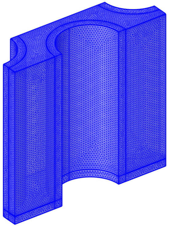
Figure A1.
Mesh adopted for the PAC unit periodic cell.
References
- Cavazzini, A.; Gritti, F.; Kaczmarski, K.; Marchetti, N.; Guiochon, G. Mass-transfer kinetics in a shell packing material for chromatography. Anal. Chem. 2007, 79, 5972–5979. [Google Scholar] [CrossRef] [PubMed]
- Horváth, K.; Gritti, F.; Fairchild, J.N.; Guiochon, G. On the optimization of the shell thickness of superficially porous particles. J. Chromatogr. A 2010, 1217, 6373–6381. [Google Scholar] [CrossRef] [PubMed]
- Felletti, S.; Catani, M.; Mazzoccanti, G.; De Luca, C.; Lievore, G.; Buratti, A.; Pasti, L.; Gasparrini, F.; Cavazzini, A. Mass transfer kinetics on modern Whelk-O1 chiral stationary phases made on fully-and superficially-porous particles. J. Chromatogr. A 2021, 1637, 461854. [Google Scholar] [CrossRef] [PubMed]
- Blumberg, L.M. Methodology of quantitative comparison of practically achievable kinetic performance of differently structured liquid chromatography columns. J. Chromatogr. A 2022, 1672, 463039. [Google Scholar] [CrossRef] [PubMed]
- Blumberg, L.M. Transport diameters of liquid chromatography columns. J. Chromatogr. A 2023, 1687, 463688. [Google Scholar] [CrossRef] [PubMed]
- Knox, J.H. Band dispersion in chromatography—A universal expression for the contribution from the mobile zone. J. Chromatogr. A 2002, 960, 7–18. [Google Scholar] [CrossRef] [PubMed]
- Schure, M.R.; Maier, R.S.; Kroll, D.M.; Davis, H.T. Simulation of packed-bed chromatography utilizing high-resolution flow fields: Comparison with models. Anal. Chem. 2002, 74, 6006–6016. [Google Scholar] [CrossRef]
- Schure, M.R.; Maier, R.S.; Kroll, D.M.; Davis, H.T. Simulation of ordered packed beds in chromatography. J. Chromatogr. A 2004, 1031, 79–86. [Google Scholar] [CrossRef]
- De Malsche, W.; Eghbali, H.; Clicq, D.; Vangelooven, J.; Gardeniers, H.; Desmet, G. Pressure-driven reverse-phase liquid chromatography separations in ordered nonporous pillar array columns. Anal. Chem. 2007, 79, 5915–5926. [Google Scholar] [CrossRef]
- Nawada, S.; Dimartino, S.; Fee, C. Dispersion behavior of 3D-printed columns with homogeneous microstructures comprising differing element shapes. Chem. Eng. Sci. 2017, 164, 90–98. [Google Scholar] [CrossRef]
- Umatheva, U.; Chen, G.; Ghosh, R. Computational fluid dynamic (CFD) simulation of a cuboid packed-bed chromatography device. Chem. Eng. Res. Des. 2019, 152, 393–401. [Google Scholar] [CrossRef]
- Parmentier, F. Effect of diffusional bridging in multicapillary packing. Comptes Rendus Chim. 2020, 23, 415–431. [Google Scholar] [CrossRef]
- Broeckhoven, K.; Desmet, G. Advances and innovations in liquid chromatography stationary phase supports. Anal. Chem. 2020, 93, 257–272. [Google Scholar] [CrossRef] [PubMed]
- Regnier, F.E. Microfabricated monolith columns for liquid chromatography. sculpting supports for liquid chromatography. J. High Resolut. Chromatogr. 2000, 23, 19–26. [Google Scholar] [CrossRef]
- Slentz, B.E.; Penner, N.A.; Regnier, F. Geometric effects of collocated monolithic support structures on separation performance in microfabricated systems. J. Sep. Sci. 2002, 25, 1011–1018. [Google Scholar] [CrossRef]
- De Pra, M.; Kok, W.T.; Gardeniers, J.G.; Desmet, G.; Eeltink, S.; van Nieuwkasteele, J.W.; Schoenmakers, P.J. Experimental study on band dispersion in channels structured with micropillars. Anal. Chem. 2006, 78, 6519–6525. [Google Scholar] [CrossRef] [PubMed]
- De Pra, M.; De Malsche, W.; Desmet, G.; Schoenmakers, P.J.; Kok, W.T. Pillar-structured microchannels for on-chip liquid chromatography: Evaluation of the permeability and separation performance. J. Sep. Sci. 2007, 30, 1453–1460. [Google Scholar] [CrossRef]
- De Pra, M.; Kok, W.T.; Schoenmakers, P.J. Topographic structures and chromatographic supports in microfluidic separation devices. J. Chromatogr. A 2008, 1184, 560–572. [Google Scholar] [CrossRef]
- Callewaert, M.; De Beeck, J.O.; Maeno, K.; Sukas, S.; Thienpont, H.; Ottevaere, H.; Gardeniers, H.; Desmet, G.; De Malsche, W. Integration of uniform porous shell layers in very long pillar array columns using electrochemical anodization for liquid chromatography. Analyst 2014, 139, 618–625. [Google Scholar] [CrossRef]
- De Malsche, W.; Clicq, D.; Verdoold, V.; Gzil, P.; Desmet, G.; Gardeniers, H. Integration of porous layers in ordered pillar arrays for liquid chromatography. Lab Chip 2007, 7, 1705–1711. [Google Scholar] [CrossRef]
- Malsche, W.D.; Gardeniers, H.; Desmet, G. Experimental study of porous silicon shell pillars under retentive conditions. Anal. Chem. 2008, 80, 5391–5400. [Google Scholar] [CrossRef]
- Brenner, H.; Gaydos, L.J. The constrained brownian movement of spherical particles in cylindrical pores of comparable radius: Models of the diffusive and convective transport of solute molecules in membranes and porous media. J. Colloid Interface Sci. 1977, 58, 312–356. [Google Scholar] [CrossRef]
- Brenner, H.; Edwards, D.A. Macrotransport Processes; Butterworth-Heinemann: Oxford, UK, 1993. [Google Scholar]
- Adrover, A.; Cerbelli, S.; Giona, M. Taming axial dispersion in hydrodynamic chromatography columns through wall patterning. Phys. Fluids 2018, 30, 042002. [Google Scholar] [CrossRef]
- Adrover, A.; Cerbelli, S. Laminar dispersion at low and high Peclet numbers in finite-length patterned microtubes. Phys. Fluids 2017, 29, 062005. [Google Scholar] [CrossRef]
- Adrover, A.; Passaretti, C.; Venditti, C.; Giona, M. Exact moment analysis of transient dispersion properties in periodic media. Phys. Fluids 2019, 31, 112002. [Google Scholar] [CrossRef]
- Adrover, A.; Venditti, C.; Giona, M. Laminar dispersion at low and high Peclet numbers in a sinusoidal microtube: Point-size versus finite-size particles. Phys. Fluids 2019, 31, 062003. [Google Scholar] [CrossRef]
- Giona, M.; Venditti, C.; Adrover, A. On the long-term simulation of stochastic differential equations for predicting effective dispersion coefficients. Phys. A Stat. Mech. Its Appl. 2020, 543, 123392. [Google Scholar] [CrossRef]
- Biagioni, V.; Venditti, C.; Adrover, A.; Giona, M.; Cerbelli, S. Taming Taylor-Aris dispersion through chaotic advection. J. Chromatogr. A 2022, 1673, 463110. [Google Scholar] [CrossRef]
- Venditti, C.; Cerbelli, S.; Procopio, G.; Adrover, A. Comparison between one-and two-way coupling approaches for estimating effective transport properties of suspended particles undergoing Brownian sieving hydrodynamic chromatography. Phys. Fluids 2022, 34, 042010. [Google Scholar] [CrossRef]
- Venditti, C.; Biagioni, V.; Adrover, A.; Cerbelli, S. Impact of transversal vortices on the performance of Open-Tubular Liquid Chromatography. J. Chromatogr. A 2022, 1685, 463623. [Google Scholar] [CrossRef]
- Venditti, C.; Giona, M.; Adrover, A. Exact moment analysis of transient/asymptotic dispersion properties in periodic media with adsorbing/desorbing walls. Phys. Fluids 2022, 34, 122013. [Google Scholar] [CrossRef]
- Venditti, C.; Huygens, B.; Desmet, G.; Adrover, A. Moment analysis for predicting effective transport properties in hierarchical retentive porous media. J. Chromatogr. A 2023, 1703, 464099. [Google Scholar] [CrossRef] [PubMed]
- Huygens, B.; Venditti, C.; Adrover, A.; Desmet, G. Nonadditivity and Nonlinearity of Mobile and Stationary Zone Mass Transfer Resistances in Chromatography. Anal. Chem. 2023, 95, 15199–15207. [Google Scholar] [CrossRef] [PubMed]
- Moussa, A.; Huygens, B.; Venditti, C.; Adrover, A.; Desmet, G. Theoretical computation of the band broadening in micro-pillar array columns. J. Chromatogr. A 2024, 1715, 464607. [Google Scholar] [CrossRef] [PubMed]
- Adrover, A.; Venditti, C.; Desmet, G. An alternative general model for the effective longitudinal diffusion in chromatographic beds filled with ordered porous particles. J. Chromatogr. A 2023, 1715, 464598. [Google Scholar] [CrossRef] [PubMed]
- Plumb, O.; Whitaker, S. Diffusion, adsorption and dispersion in porous media: Small-scale averaging and local volume averaging. In Dynamics of Fluids in Hierarchical Porous Media; Academic Press, Inc.: San Diego, CA, USA, 1990; pp. 97–148. [Google Scholar]
- Paine, M.; Carbonell, R.; Whitaker, S. Dispersion in pulsed systems—I: Heterogenous reaction and reversible adsorption in capillary tubes. Chem. Eng. Sci. 1983, 38, 1781–1793. [Google Scholar] [CrossRef]
- Plumb, O.A.; Whitaker, S. Dispersion in heterogeneous porous media: 1. Local volume averaging and large-scale averaging. Water Resour. Res. 1988, 24, 913–926. [Google Scholar] [CrossRef]
- Yan, X.; Wang, Q.; Bau, H.H. Dispersion in retentive pillar array columns. J. Chromatogr. A 2010, 1217, 1332–1342. [Google Scholar] [CrossRef]
- Yan, X.; Wang, Q.; Li, N. Predictive model of solute transport with reversible adsorption in spatially periodic hierarchical porous media. J. Chromatogr. A 2015, 1407, 69–75. [Google Scholar] [CrossRef]
- Giddings, J.C. The role of lateral diffusion as a rate-controlling mechanism in chromatography. J. Chromatogr. A 1961, 5, 46–60. [Google Scholar] [CrossRef]
- Desmet, G.; Broeckhoven, K.; De Smet, J.; Deridder, S.; Baron, G.; Gzil, P. Errors involved in the existing B-term expressions for the longitudinal diffusion in fully porous chromatographic media: Part I: Computational data in ordered pillar arrays and effective medium theory. J. Chromatogr. A 2008, 1188, 171–188. [Google Scholar] [CrossRef] [PubMed]
Disclaimer/Publisher’s Note: The statements, opinions and data contained in all publications are solely those of the individual author(s) and contributor(s) and not of MDPI and/or the editor(s). MDPI and/or the editor(s) disclaim responsibility for any injury to people or property resulting from any ideas, methods, instructions or products referred to in the content. |
© 2024 by the authors. Licensee MDPI, Basel, Switzerland. This article is an open access article distributed under the terms and conditions of the Creative Commons Attribution (CC BY) license (https://creativecommons.org/licenses/by/4.0/).