Article

Study on Homogeneous Reduction Technology in Gas Samples for Oil and Gas Loss

1
Technical Test Centre of Sinopec Shengli OilField, Dongying 257000, China
2
Testing and Evaluation Research Co., Ltd. of Sinopec Shengli OilField, Dongying 257000, China
3
College of Oceanography and Space Informatics, China University of Petroleum (East China), Qingdao 266580, China
*
Author to whom correspondence should be addressed.
Separations 2023, 10(5), 294; https://doi.org/10.3390/separations10050294
Submission received: 29 December 2022 / Revised: 7 April 2023 / Accepted: 9 April 2023 / Published: 5 May 2023
(This article belongs to the Topic Oil, Gas and Water Separation Research)

Abstract

:
The process of storing oil depots and combined station tanks is affected by factors such as process technology, equipment, and management methods. Inevitably, some heavy hydrocarbon components will condense. According to the available literature, the existing detection methods are not enough to accurately measure the component composition so that the proportion of heavy hydrocarbon substances in the lost gas is reduced. In this paper, by inventing a homogeneous reduction device, the lost gas in the entire laboratory process was kept in a homogeneous state so that the gas components were well-retained. Using the homogeneous reduction method and a traditional inspection method, gas chromatography was performed on a standard gas and the on-site lost gas, respectively. The standard gas measurement results show that the mean deviations of the homogeneous reduction method and the traditional test method were −3.45% and −11.62%, respectively, and the reduction degree reached 96.55% with the homogeneous reduction method. The results of the on-site gas loss measurements show that the proportions of most hydrocarbon substances in each lost gas increase to varying degrees after using the homogeneous reduction technology. Therefore, it is proved that these components can be better preserved using the homogeneous reduction method. It can effectively avoid the condensation of components, which is of great significance to the study of oil and gas loss.

1. Introduction

Petroleum and petroleum products are mixtures of a variety of hydrocarbons, of which the light component is highly volatile [1,2,3,4]. The evaporation loss of oil is large, and the oil loss rate is as high as 1.5~3% [5]. The study of oil and gas loss in storage tanks is conducive to discovering the loss problems in the production process of crude oil [6,7,8,9,10,11,12,13], and carrying out the corresponding transformations is conducive to promoting low-carbon energy saving and improving the economic benefits in oilfields [14,15].
The formula for quantitative research on oil evaporation loss in the world is mainly recommended by the American Petroleum Institute and is obtained by summarizing and analyzing the respiration process of oil in a tank, and its practicality is wide, but when using formulas for calculations, the precise values of various parameters are first required. The values of these parameters are generally more difficult to determine, and enterprises are simplified, so the experimental error is large [16]. In addition to the quantitative research formula, Waheed [17] and Haelssig et al. [18] adopted a combination of the mass transfer equation and the turbulence model based on Fair’s law to study the mass transfer diffusion phenomenon and linked the leakage amount with the disturbance of external wind speed so that the simulation results would be more consistent with the experimental results. L. Chernyak et al. [19] studied the effect of oil and gas loss on oil quality through experiments. Busahmin et al. [20] studied the surface tension between a mineral oil system and a crude oil system through experiments. The results showed that the surface tension of the mineral oil system was higher than that of the foamy crude oil system based on the experimental principle of gas–liquid interfacial tension. Hassanvand et al. [21] conducted a CFD (computational fluid dynamics) simulation of oil evaporation loss in the process of sending and receiving oil in a vertical storage tank containing gasoline, and the results showed that the total evaporation loss of oil can be significantly reduced when the speed of receiving the oil in the tank is increased. Farzaneh-Gord et al. [22] studied the evaporation loss of crude oil in an external floating roof storage tank, verified the numerical model for the tank temperature measurement at different times of the day, and analyzed the influence of the coating on the oil loss from the outer surface of the tank. The results showed that the evaporation loss of crude oil is lowest when the outer surface of a tank is coated with light-colored paint. Liang et al. [23] analyzed the temperature change process in a tank and combined this with programming to simulate the effect of temperature change on oil evaporation. Gao et al. [24], on the basis of the research on and analysis of the mechanism of evaporation loss, proposed a variety of effective consumption reduction measures, which achieve good functional significance. Zhang et al. [25] designed and produced a small stainless-steel cone tank, which they used to measure the temperature change of the gas space and oil in a tank using equidistant thermal resistance temperature measuring points with four equally spaced temperature measuring points. An austenitic gas analyzer was selected to record and analyze the change in the concentration. Zuo et al. [26] gave a calculation formula that is more suitable for China at different times on the basis of discussing and comparing the existing respiratory loss formulas. Wang et al. [27,28] studied the oil and gas diffusion law of oil and gas in the oil tank recovery process and discussed the influence of various variables on oil and gas diffusion with the help of TRNSYS. Huang et al. [29,30,31,32] established a small conical top metal evaporation loss test platform in view of the serious evaporation loss problem in the process of oil storage and transportation and experimentally measured the evaporation loss of a small conical top gasoline tank, but due to safety and the complex methods and other issues, it is not suitable for on-site monitoring. On the basis of a basic parameter test of some crude oil tanks, the flash emissions and respiratory emissions of the tanks were calculated using an online monitoring system, but the greenhouse gas emissions were not studied [33]. Zheng et al. [34] carried out research on monitoring technology in view of the respiratory loss of Shengli Oilfield storage tanks, designed the mechanical structure of a monitoring system, and proposed a monitoring scheme for all parameters and key parameters. Through the design of hardware circuits and software, the goal of online monitoring has been achieved, but there are many monitoring points, the monitor is electrified, and the problem of potential safety hazards is still difficult to solve. Chen et al. [35] used infrared thermal imaging technology to study the respiratory loss of a storage tank, whereby the infrared thermal imager can accurately measure the temperature of a target without contacting the measurement object and present its temperature distribution, but the disadvantages of infrared detection are that the detection sensitivity is related to the thermal emissivity, the detection time–temperature relationship is strict, and the cost is high.
In order to measure the oil and gas loss in a field more accurately and safely, we propose a novel gas sample homogeneous reduction technology. A set of experimental devices with a constant-temperature heating box, constant-temperature transmitter, and constant-temperature input gas pipeline as their cores were designed. By setting an appropriate temperature, the components flow in a homogeneous state during gas sample collection, transfer, and laboratory testing so that the components are stored and collected relatively completely. The condensation of components is effectively reduced. This has important technical reference value for achieving the efficient detection of oil and gas loss and reducing oil and gas loss.

2. Experimental Scheme and Design

2.1. Laboratory Equipment

In view of the characteristics of the lost gas, the differences in the boiling point of each component were used to control a certain temperature to maintain the lost gas in a homogeneous state during the whole detection process. This effectively ensures that the lost gas reaches the required laboratory accuracy. Condensation occurs when a gas sample is collected into the transmitter. In this paper, a constant-temperature transfer device was designed to continuously heat the gas sample during the transfer process to keep the gas sample in a homogeneous state. For the condensation problem, this paper designed a constant-temperature heating box. By setting an appropriate temperature in the constant-temperature heating box, a gas sample’s components are kept in a homogeneous state. In order to continuously heat the gas sample during the connection of the chromatograph [36,37,38] and the sampling bag, a constant-temperature input gas tube was designed.

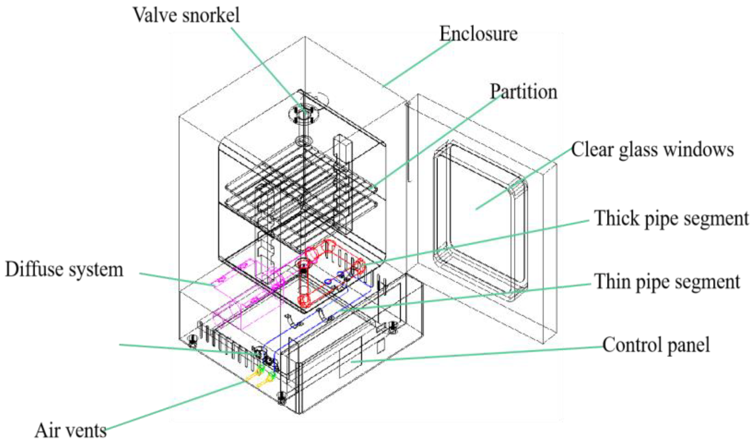
2.2. Schematic Structure Design of Heating Box

The device in Figure 1 mainly plays the role of gas sample transfer. The collected gas samples are stored in a constant-temperature heating box, which avoids condensation during storage. According to the boiling points of the various alkane components, the constant-temperature heating box sets an appropriate temperature to ensure that the gas sample remains in a homogeneous state. The heating system is a key device for the continuous supply of hot air. The internal pipes of the heating box are made of metal.

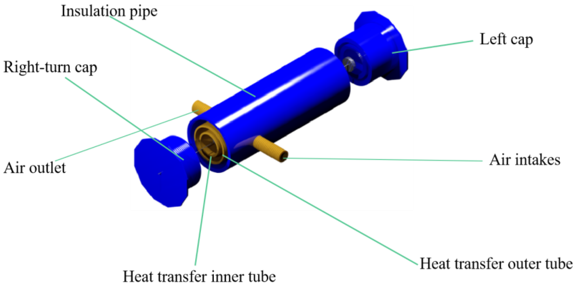
2.3. Transfer Device Design

The device in Figure 2 is mainly used for gas sample collection. The consumption gas is evaporated from the oil product and enters the transfer device through the input tube. Through the continuous heating of the thermostatic transfer device and the input tube, the lost gas is always kept in a homogeneous state. The transfer device and the input tube adopt the shape of a syringe. The material of the transfer device is made of glass and is 100 mL in volume. The material of the heat adapter, the input tube, and the sleeve was finally selected as brass H65. The material of the insulation pipe is PVC plastic. The left and right caps are made of POM. The inner surface of the sample is coated with PTFE (poly tetra fluoroethylene). The obtained coating is acid- and alkali-resistant and insoluble in various organic solvents, which can effectively prevent the adsorption of trace components in the sample and improve the corrosion resistance of the sampler.

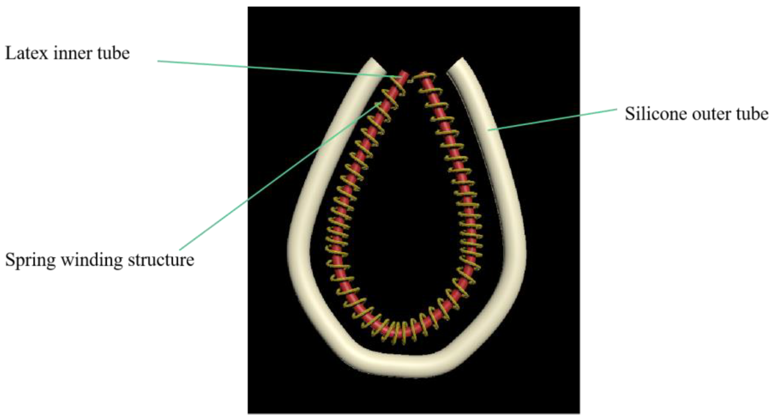
2.4. Constant-Temperature Gas Transmission Pipeline Design

Saeid et al. [39] simulated the jet impingement heat transfer process of a moving plate under steady laminar flow conditions. The study showed that the convective heat transfer of the moving plate was related to thermal conductivity. Based on this, this paper designed a constant-temperature conveying gas pipe, as shown in Figure 3. This is a device that plays a connecting and continuous heating process during the entire gas sample collection, transfer, and laboratory process. The sampled gas needs to be continuously heated and transported through the constant-temperature gas delivery pipeline. The gas transmission pipeline heating device is composed of a sampling tube, spring tube, and silicone tube. The space between the sampling tube and the silicone tube is the hot air channel. During sampling and testing, the sampling tube is continuously heated through the intermediate heating channel so that the gas components do not condense. The intermediate spring tube mainly plays the role of isolation to prevent the latex tube from adhesion to the silicone tube during the heating process. The thickness of the silicone tube is thicker than the sampling tube and the spring tube, and its purpose is to insulate heat.

3. Experimental Parameter Design

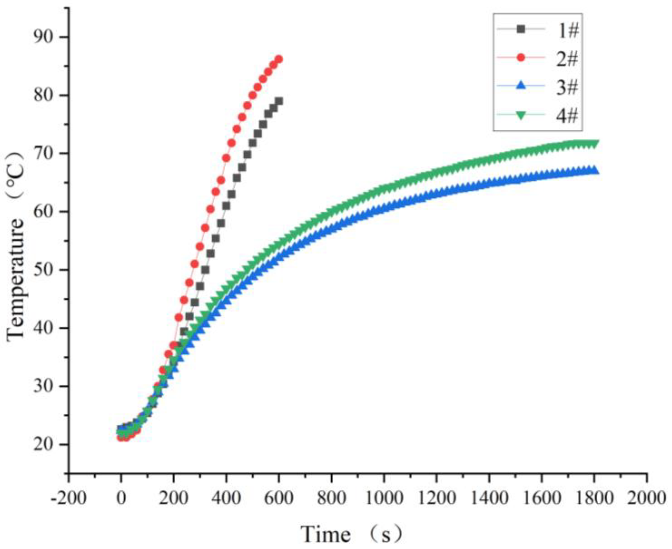
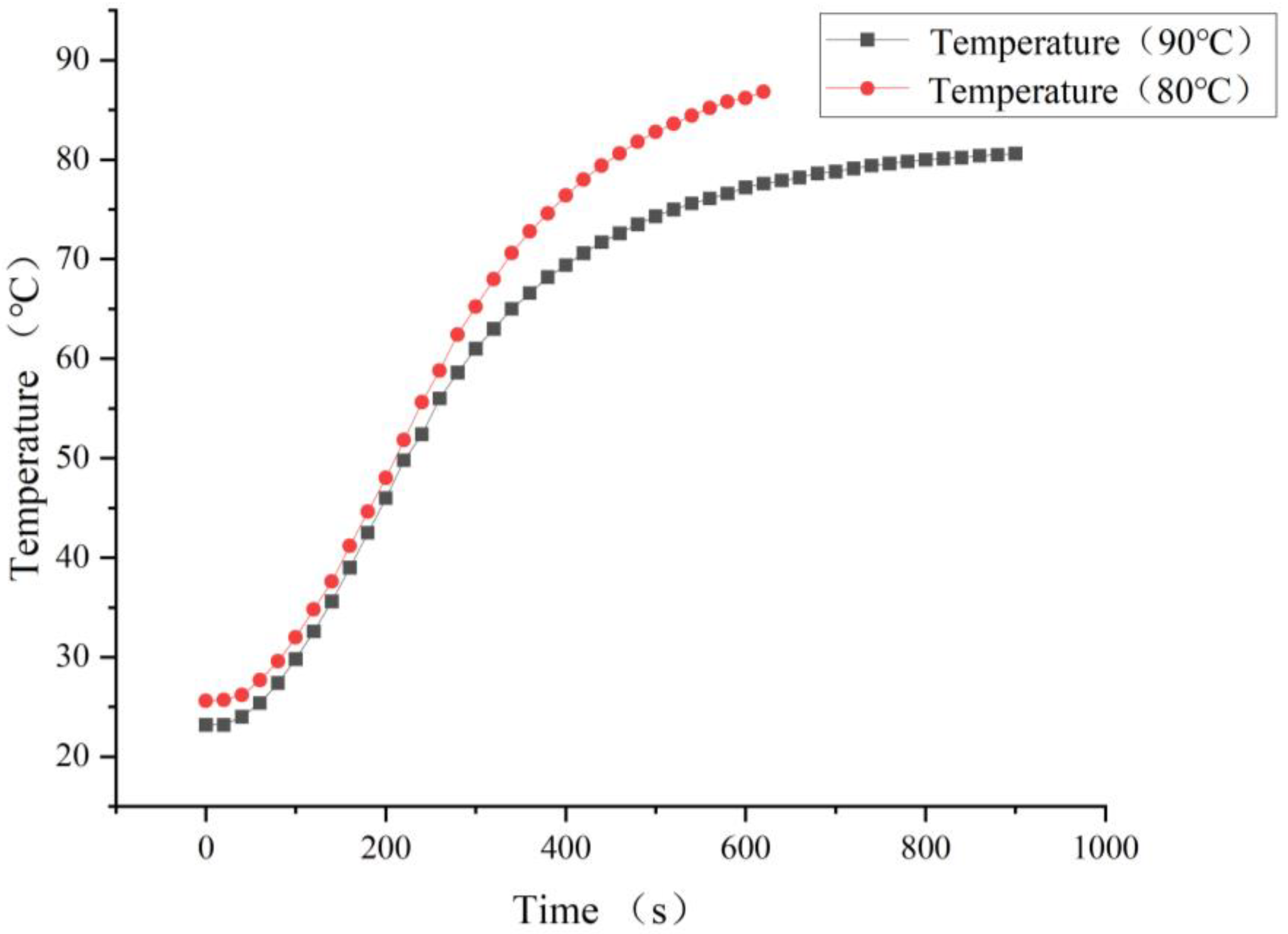
3.1. Heating Temperature of the Transmitter

According to the upper limit of the crude oil heating temperature in Sinopec Oilfield Station, 80 °C was selected as the control temperature of the homogeneous reduction technology. In order to clarify the heating performance of the thermostatic transmitter, thermal response tests of 3 heating strips were carried out for 5 min, and the digital temperature value was recorded every 5 s. In addition, the heating belt was fixed onto the heat transfer tube of the transmitter, and the temperature of the heating belts No. 1, No. 2, and No. 3 was set to 80–90 °C. The No. 1 and No. 2 heating strips were used for the 100 mL constant-temperature transfers, and the No. 3 heating strip was used for chromatographs supporting the constant-temperature transmitters. The heating response test data of the heating belt are shown in Figure 4. It can be seen from the figure that the heating belt took time to heat from the ambient temperature to 80 °C within 90~120 s; the heating speed meets the design requirements; after heating to 80 °C, the temperature fluctuation range was 78~82 °C; and the temperature difference was ± 2 °C.
When testing the 100 mL constant-temperature transmitter, 4 different heating conditions were numbered, and the heating conditions inside the No. 521 glass syringe (No. 1 heating belt; 90 °C), the inner wall of the No. 521 glass syringe (No. 1 heating belt; 90 °C), the inside of the No. 514 glass syringe (No. 2 heating belt; 80 °C), and the inner wall of the No. 514 glass syringe (No. 2 heating belt; 80 °C) were numbered 1#, 2#, 3#, and 4#, in turn. The thermal response test data of the 100 mL thermostatic transmitter are shown in Figure 5. It can be seen in Figure 5 that when the temperature of the No. 1 heating belt was set to 90 °C and the temperature of the No. 2 heating belt was set to 80 °C, the inner wall and the inside of the No. 1 heating belt syringe barrel reached 80 °C significantly faster than the No. 2 heating belt. At the time of the test, the ambient temperature was approximately 25 degrees, and the time spent for the inner wall of the No. 1 heating syringe barrel to reach 80 °C was 8 min and 20 s, and the internal time was 10 min and 20 s. The heating time of the inner wall of the No. 2 heating belt was only 71.8 °C when the heating time was 30 min, and the internal temperature was only 67 °C. Based on the influences of the heating belt temperature and heating belt type on the heating speed, the No. 1 heating belt and No. 521 glass syringe were selected, and the heating temperature was set to 90 °C. When used on-site, the heating time of the 100mL thermostatic transmitter was at least 10 min.
From the results of the thermal response test of the thermostatic transducer supporting the chromatograph (Figure 6), the test data of the thermostatic transmitter are 80 °C and 90 °C. From the results of the thermal response test of the thermostatic transducer supporting the chromatograph (Figure 4), it can be seen that when the internal temperature of the transducer reached 80 °C, the time taken to reach the heating temperature of 90 °C was significantly faster than that for 80 °C. When the heating temperature was set to 90 °C, the time taken to reach 80 °C inside the transmitter was 7 min and 40 s, and when the heating temperature was set to 80 °C, the time taken to reach 80 °C inside the transmitter was 13 min and 20 s. Therefore, the heating temperature of the constant-temperature transfer device equipped with the chromatograph was set to 90 °C. The heating time was at least ten minutes.

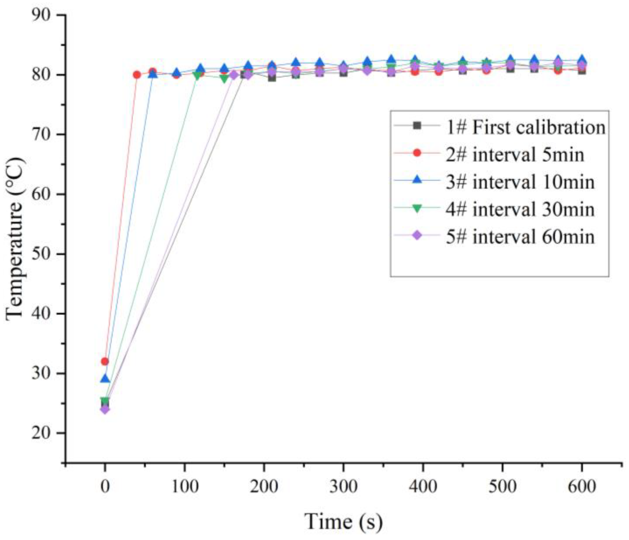
3.2. Hot Air System Temperature

The selected hot air system power was 3300 W, the working voltage was 220 V, and the minimum air volume was 400 L/min. The time required for the hot air system to reach 80 °C and the temperature control accuracy were tested. The heating system was tested for thermal stability for 10 min using a high-precision thermometer, as shown in Figure 7. The heating system took no more than 3 min to reach 80 °C, and after the temperature reached 80 °C, the thermal stability performance was good, and the temperature control accuracy was ± 3 °C. When the hot air system was tested for the first time, it took 175 s to reach 80 °C, which was a long time. After 5 min of testing, it took 40 s to reach 80 °C, which was greatly shortened, because the parts and heating elements in the heating system were at a high-temperature level. After 10 min, 30 min, and 60 min tests, the time required to reach 80 °C gradually increased. In general, the thermal response performance and temperature control accuracy of the heating system can meet the requirements of this experiment.

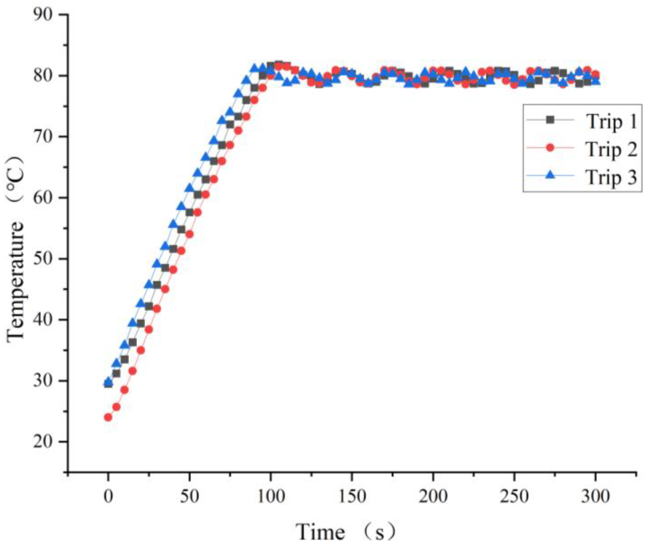
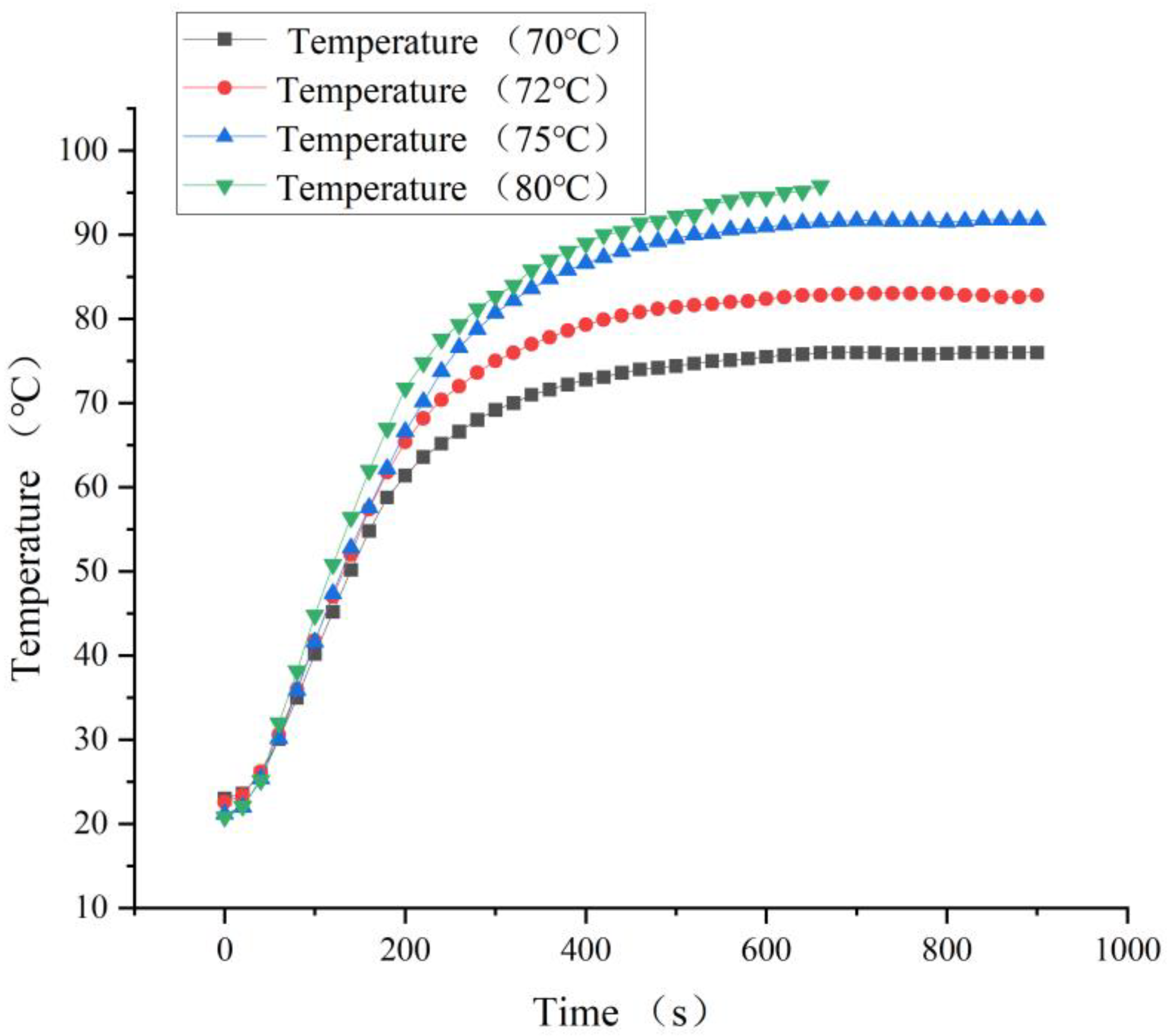
3.3. Heating Temperature of the Constant-Temperature Conveying Gas Pipe

The constant-temperature gas transmission pipe was installed in the constant-temperature heating box for the gas transmission test. According to the upper limit of the crude oil heating temperature of the Sinopec oil station, the heating temperature should be similar to the temperature in the tank. In order to clarify the actual temperature situation in the constant-temperature gas transmission pipe, the temperature of the heating belt of the constant-temperature gas pipeline was set to 70, 72, 72, and 80 °C. It can be seen in Figure 8 that when the temperature of the heating belt was set to 70 °C, the heating time was 600 s, the temperature in the gas pipeline was 76 °C, and the final temperature was maintained at 76 °C, which cannot meet the requirement for 80 °C of the homogeneous reduction device. When the heating temperature was set to 75 or 90 °C, it could reach 80 °C when the heating time was 300 s, but at this time, the internal temperature of the gas hose continued to rise, reaching a maximum of 95 °C, which is a potential safety hazard. When the temperature of the heating belt was set to 72 °C, the time required to reach 80 °C was 440 s, and the subsequent temperature rises to 83 °C stopped meeting the heating performance requirements. Therefore, the heating band temperature of the constant-temperature gas pipeline was set to 72 °C, and the heating time was at least 8 min.

3.4. The Experimental Scheme

The homogeneous reduction device includes a constant-temperature transfer device, a constant-temperature heating box, a constant-temperature gas transmission pipe, and various sampling and laboratory transportation tools. According to the sampling, transportation, and laboratory procedures of on-site consumption gas and the standard national emission standards for natural gas [40], with the homogeneous reduction device, the oil and gas loss components were accurately measured, and two sets of homogeneous reduction technology application schemes are provided.
Option one:
A: The standard gas is stored in a 1 Mpa cylinder. The gas composition is collected and detected using homogeneous reduction technology. The sampling bag is heated in a heating box for a period of time, and the gas is extracted with a constant-temperature transfer device and introduced into the gas chromatograph.
B: The standard gas is stored in a 1 Mpa cylinder. The gas composition is collected and detected via direct intake. The gas is collected with a sampling bag and introduced into the gas chromatograph with a transfer device.
Comparison between Method A and Method B.
Option two:
C: By collecting the gas from the site, the gas is collected into airbags. The gas components are collected and detected via homogeneous reduction. The gas is collected with the constant-temperature transmitter. The transfer is put into the constant-temperature insulation box for storage, and then the constant-temperature transfer device is used to import the gas chromatograph.
D: By collecting the gas from the site, the gas is collected into airbags. The gas composition is collected and detected via direct intake. The gas is collected in a sampling bag and introduced into the gas chromatograph with a transfer device.
Comparison between Method C and Method D.

3.5. Gas Chromatography–Mass Spectrometry Analysis Methods

The column for gas chromatography was selected as 30 m × 0.32 mm × 10 μm (TG-BONDQ). Trace GC Ultra was selected as the gas chromatography system, and ultra-pure helium with a purity of more than 99% was selected as the carrier gas. The carrier gas flow rate was 1.2 mL/min. The ion source temperature was 290 °C. The transmission line temperature was 270 °C. The injection temperature was 114 °C. The injection volume was 300 μL. The shunt ratio was 25. The initial column temperature of the heating furnace chamber was configured as follows: 50 °C for 2 min, then heat to 270 °C at a rate of 60 °C/min and hold for 6 min. The scanning ion range was 10~115 in order to avoid air peaks and water peaks, and the signal was checked after 4 min. The mass spectrometer was equipped with an electron bombardment power source (EI). The acquisition rate was in SIM mode, and the acquisition rate was >240 scans/sec. The mass range was 1.2–1100 u. The quality of the gases was analyzed with chromatographic analysis using thermal desorption, purge trap, solid-phase extraction, solid-phase microeconomics, and liquid-phase microextraction. Manual injection was performed using a thermostatic transmitter. When quantitative analysis is carried out with a gas chromatograph, the sample follows the flow of helium, and the components in the sample are adsorbed–desorbed many times according to the principle of similar miscibility, and each component is separated after passing through the column, leaving the column in turn, and after detection in the detector, each component flowing out of the column is converted into an electrical signal via the detector and then processed with the amplifier to show the chromatographic peak of each component in the sample on the recorder. When a sample is qualitatively analyzed using mass spectrometry with a gas-phase mass spectrometer, because all samples are in a gaseous state, the volatile sample is ionized via an EI source, and the electron flow with extremely high energy emitted by the filament is used to ionize the sample via collision, that is, fragments such as molecular ions are generated. Unknown compounds are then searched and matched with the data library to determine the component class. When performing quantitative analysis, because of the presence of C5 and C6 volatile components, and because the gas sample components are more complex, it is necessary to choose the more commonly used area normalization method with accurate and simple characteristics, which can achieve all the components of the column effluent gas sample in the linear range being detected with the detector. If the operating experimental conditions change, this will not affect the accuracy of the gas sample injection amount during analysis.

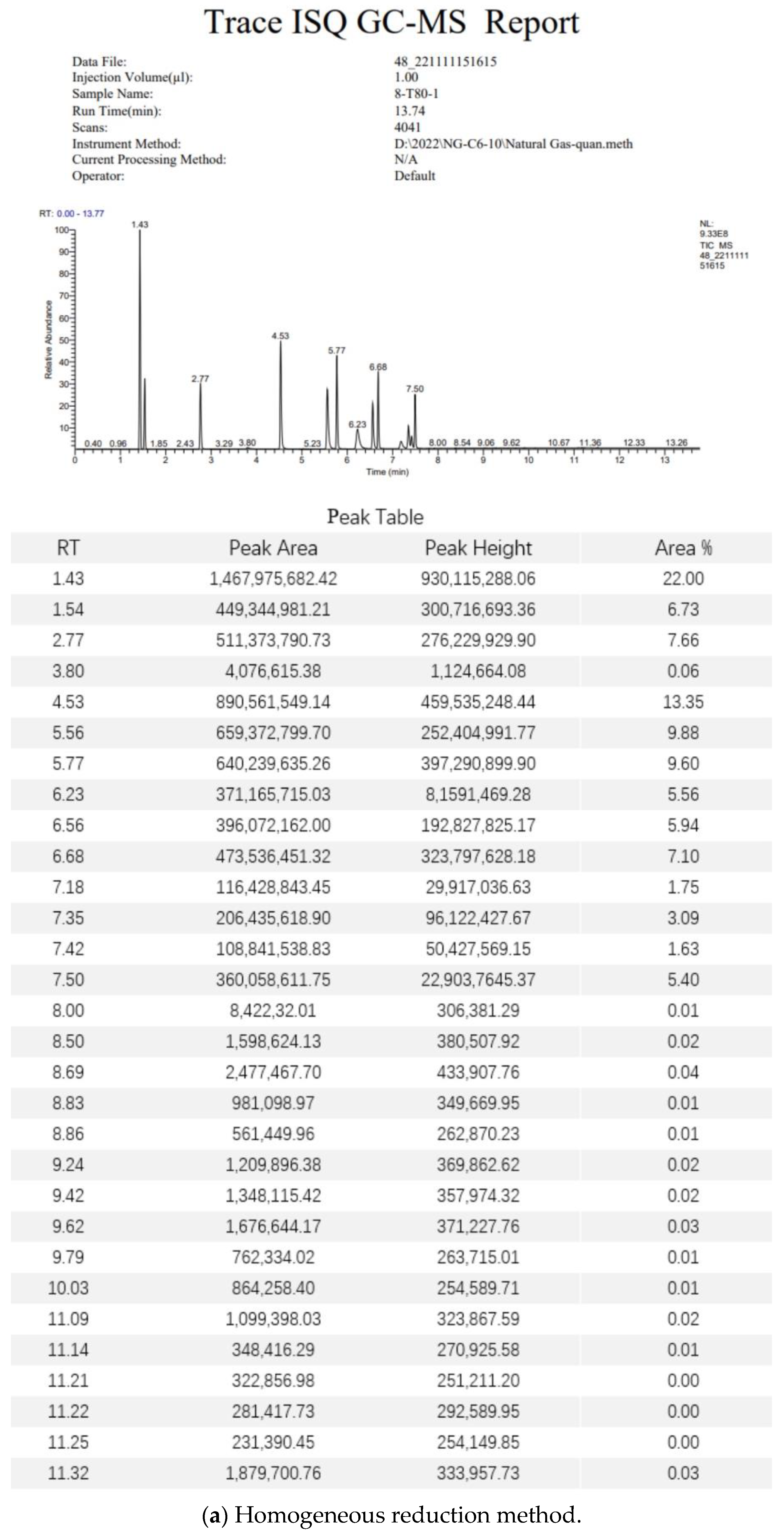
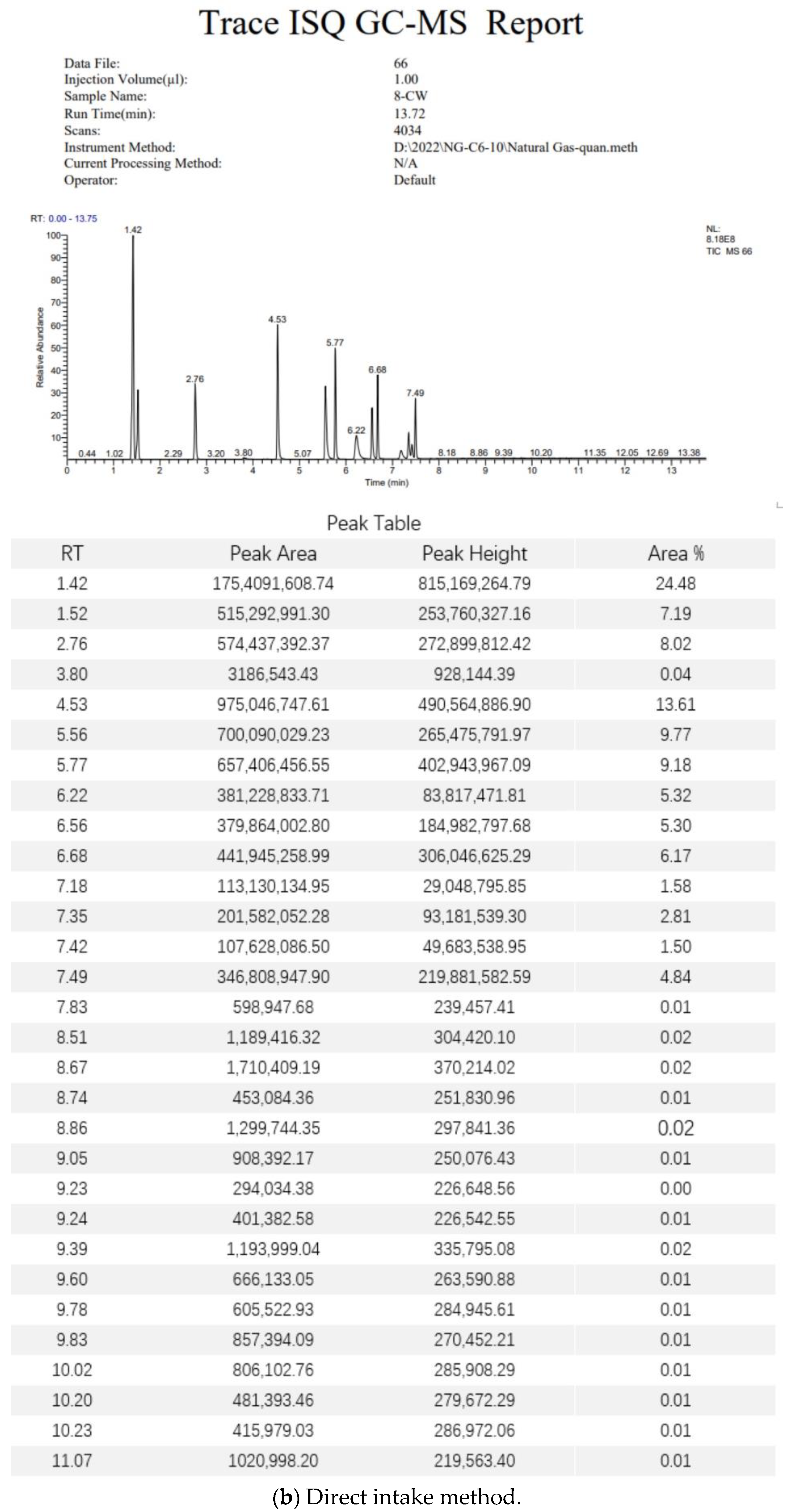
3.6. Standard Gas Test Data Analysis

After collecting the gas lost at the site, the gas sample was determined using gas chromatography. We obtained the test report from the gas chromatography–mass spectrometer and analyzed the gas sample components (Figure A1). After the post-processing of the test data, the results of the homogeneous reduction method and direct intake method for the gas sample were determined. The average deviations of the two methods were calculated according to the measurement results. The average deviation is the mean value of the absolute value of the difference between each original data value and the arithmetic mean, which is represented by the symbol A.D. (average deviation) to reflect the average difference between each marker value and the arithmetic mean, as shown in Table 1. After analyzing the processing results and filtering the noise data, the A.D. values of the homogeneous reduction method and the direct intake method were −3.45% and −11.62%, respectively, and the reduction degrees of the homogeneous reduction method and direct air intake method were 96.55% and 88.38%, respectively. It is concluded that the use of the homogeneous reduction method can better retain the components, which is of great significance to the study of oil and gas loss.

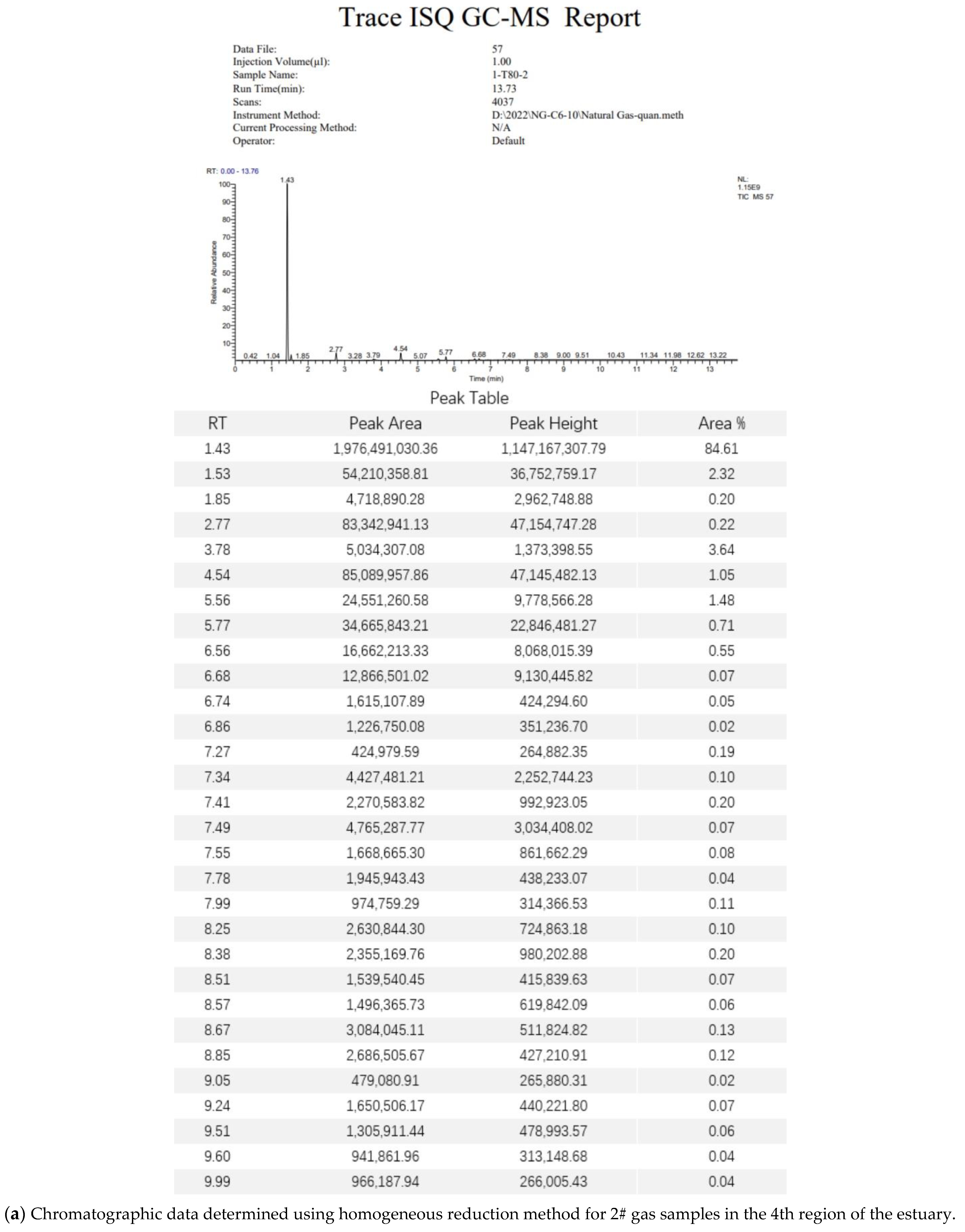
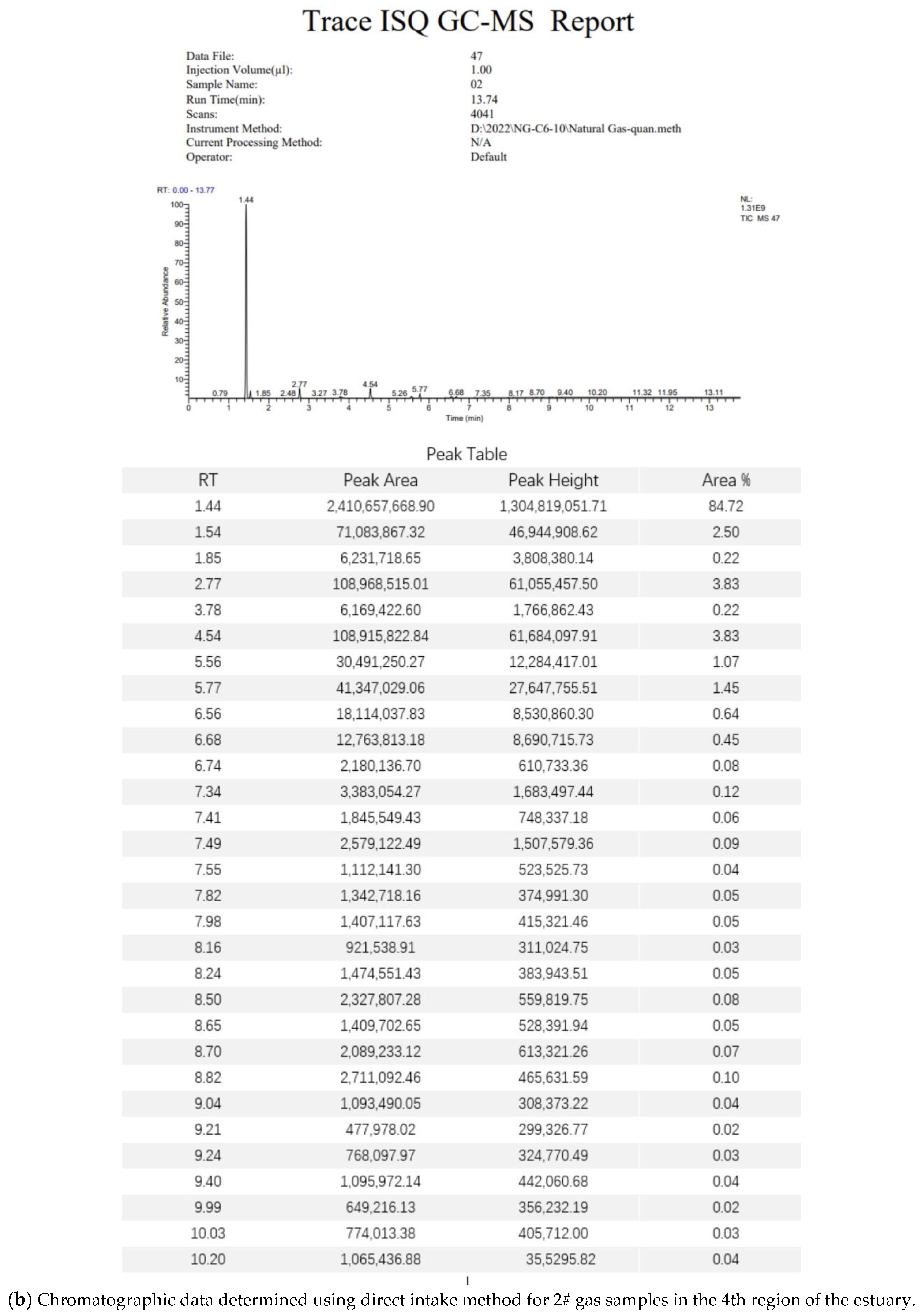
3.7. Field Gas Loss Measurement Data Analysis

The gas samples were measured using gas chromatography. The mass spectrometer test report of the on-site gas loss is shown in Figure A2. The composition data of the gas measurements were obtained employing a uniform reduction method and the standard method, as shown in Table 2. It can be seen that the homogeneous reduction technology has a significant effect on the experimental accuracy for on-site gas loss. After the use of the homogeneous reduction technology, the proportion of hydrocarbon substances in the test value increased greatly, and some hydrocarbon substances that cannot be detected using the direct intake method were added. According to the order of the 2# gas samples in the 4th area of the Hekou, Yongyi Lian primary settlement tank gas sample, Yongyi Lian secondary settlement tank gas sample, and Yongyi Lian external transport tank gas sample, the improvements in the laboratory accuracy using the homogeneous reduction method were 26.96%, 53.46%, 38.16%, and 55.40%, respectively.

4. Conclusions

Based on the meteorological data, the lost gas testing process, and the physical properties of the hydrocarbon components of each oilfield of Sinopec, it was determined that there would be obvious cooling and condensation in the two links of lost gas collection and laboratory testing, which was the key problem leading to the low accuracy of lost gas testing. According to the available literature, the existing detection methods are not enough to accurately measure component composition, so the proportion of heavy hydrocarbon substances in the lost gas is reduced. In view of the cooling and condensation phenomenon in collection and laboratory tests, the homogeneous reduction method was used in this paper so that the lost gas in the whole laboratory process was kept in a uniform state so that the gas components were well-retained. In this paper, the homogeneous reduction method and the direct intake method were compared by using standard gas and on-site lost gas. The A.D. values of the homogeneous reduction method and direct intake method for standard gas were −3.45% and −11.62%, respectively, and the reduction degree reached 96.55% with the homogeneous reduction method. The uniform reduction method improved the measurement accuracy of gas loss in each field by 26.96%, 53.46%, 38.16%, and 55.40%. The results show that the use of the homogeneous reduction method can better retain components. It can effectively avoid the condensation of components, which is of great significance to the study of oil and gas loss.

Author Contributions

Conceptualization, L.F., Y.Y. and H.S.; Methodology, L.F. and Y.D.; Software, X.Z.; Validation, L.F. and Y.D.; Formal analysis, L.F., Y.Y. and X.Z.; Data curation, H.S.; Writing—original draft, L.F and Y.D.; Writing—review & editing, H.S., X.Z., X.H. and Y.D.; Supervision, X.Z. and X.H.; Project administration, L.F. and X.H.; Funding acquisition, L.F. and Y.D. All authors have read and agreed to the published version of the manuscript.

Funding

This research was funded by the National Natural Science Foundation of China under Grant 51874335, 52274057 and 52074340, the Major Scientific and Technological Projects of CNPC under Grant ZD2019-183-008, the Major Scientific and Technological Projects of CNOOC under Grant CCL2022RCPS0397RSN, the Science and Technology Support Plan for Youth Innovation of University in Shandong Province under Grant 2019KJH002, 111 Project under Grant B08028.

Data Availability Statement

Not applicable.

Conflicts of Interest

The authors declare no conflict of interest.

Appendix A

Figure A1. The mass spectrometer test report of the standard gas.
Separations 10 00294 g0a1aSeparations 10 00294 g0a1b
Figure A2. The mass spectrometer test report of the field gas loss.
Separations 10 00294 g0a2aSeparations 10 00294 g0a2b

References

  1. Tissot, B.P.; Welte, D.H. Composition of Crude Oils. In Petroleum Formation and Occurrence: A New Approach to Oil and Gas Exploration; Springer: Berlin/Heidelberg, Germany, 1978; pp. 333–368. [Google Scholar]
  2. Yang, S. Chemical Composition and Properties of Reservoir Fluids. In Fundamentals of Petrophysics; Springer: Berlin/Heidelberg, Germany, 2017; pp. 3–26. [Google Scholar]
  3. Faramawy, S.; Zaki, T.; Sakr, A.A.E. Natural gas origin, composition, and processing: A review. J. Nat. Gas Sci. Eng. 2016, 34, 34–54. [Google Scholar] [CrossRef]
  4. Barker, C. Origin, composition and properties of petroleum. In Developments in Petroleum Science; Elsevier: Amsterdam, The Netherlands, 1985; Volume 17, pp. 11–45. [Google Scholar]
  5. Jurušs, M.; Seile, E. Application of Loss Rates for Petroleum Products Due to Natural Wastage in Customs Procedures. Procedia Eng. 2017, 178, 377–383. [Google Scholar] [CrossRef]
  6. Zhang, L.; Chan, X.; Li, G.; Ma, X.; Zhang, K.; Gu, J.; Yao, J.; Wang, J.; Sun, H. An automatic history matching method based on ensemble and neural architecture search. J. China Univ. Pet. (Nat. Sci. Ed.) 2022, 46, 127–136. [Google Scholar]
  7. Zhang, K.; Zhao, X.; Zhang, L.; Zhang, H.; Wang, H.; Chen, G.; Zhao, M.; Jiang, Y.; Yao, J. Current status and prospect for the research and application of big data and intelligent optimization methods in oilfield development. J. China Univ. Pet. (Nat. Sci. Ed.) 2020, 44, 28–38. [Google Scholar]
  8. Zhang, K.; Zhang, H.; Zhang, L.; Yao, J. Construction and optimization method of adaptive well pattern based on reservoir uncertainty. Chin. Sci. Pap. 2017, 12, 2438–2444. [Google Scholar]
  9. Zhang, K.; Chen, G.; Xue, X.; Zhang, L.; Sun, H.; Yao, C. A reservoir production optimization method based on principal component analysis and surrogate model. J. China Univ. Pet. (Nat. Sci. Ed.) 2020, 44, 90–97. [Google Scholar]
  10. Wang, S.; Zhang, L.; Wang, J.; Wu, Y.; Zhang, K. Fault-Block reservoir production optimization based on Multi-Objective algorithm. Spec. Oil Gas Reserv. 2019, 26, 124–129. [Google Scholar]
  11. Yin, F.; Xue, X.; Zhang, C.; Zhang, K.; Han, J.; Liu, B.; Wang, J.; Yao, J. Multifidelity genetic transfer: An efficient framework for production optimization. SPE J. 2021, 26, 1614–1635. [Google Scholar] [CrossRef]
  12. Zhang, K.; Zhang, J.; Ma, X.; Yao, C.; Zhang, L.; Yang, Y.; Wang, J.; Yao, J.; Zhao, H. History matching of naturally fractured reservoirs using a deep sparse autoencoder. SPE J. 2021, 26, 1700–1721. [Google Scholar] [CrossRef]
  13. Zhang, K.; Wang, Z.; Chen, G.; Zhang, L.; Yang, Y.; Yao, C.; Wang, J.; Yao, J. Training effective deep reinforcement learning agents for real-time life-cycle production optimization. J. Pet. Sci. Eng. 2022, 208, 109766. [Google Scholar] [CrossRef]
  14. Sharma, Y.K.; Majhi, A.; Kukreti, V.S.; Garg, M.O. Stock loss studies on breathing loss of gasoline. Fuel 2010, 89, 1695–1699. [Google Scholar] [CrossRef]
  15. Jian, S.; Han, K.; Xu, X. Risk-based inspection for large-scale crude oil tanks. J. Loss Prev. Process Ind. 2012, 25, 166–175. [Google Scholar]
  16. Howari, F.M. Evaporation losses and dispersion of volatile organic compounds from tank farms. Environ. Monit. Assess. 2015, 187, 273. [Google Scholar] [CrossRef]
  17. Adekojo Waheed, M.; Henschke, M.; Pfennig, A. Mass transfer by free and forced convection from single spherical liquid drops. Int. J. Heat Mass Transf. 2002, 45, 4507–4514. [Google Scholar] [CrossRef]
  18. Haelssig, J.B.; Tremblay, A.Y.; Thibault, J.; Etemad, S.G. Direct numerical simulation of interphase heat and mass transfer in multicomponent vapour–liquid flows. Int. J. Heat Mass Transf. 2010, 53, 3947–3960. [Google Scholar] [CrossRef]
  19. Boychenko, S.; Vovk, O.; Chernyak, L.; Akinina, K. Quality and ecological safety of motor fuels. Chem. Chem. Technol. 2007, 1. [Google Scholar] [CrossRef]
  20. Busahmin, B.; Maini, B.B. Measurements of Surface Tension for Mineral and Crude Oil Systems; Defect and Diffusion Forum; Trans Tech Publ: Stafa-Zurich, Switzerland, 2019; pp. 106–113. [Google Scholar]
  21. Hassanvand, A.; Hashemabadi, S.H.; Bayat, M. Evaluation of gasoline evaporation during the tank splash loading by CFD techniques. Int. Commun. Heat Mass Transf. 2010, 37, 907–913. [Google Scholar] [CrossRef]
  22. Farzaneh-Gord, M.; Nabati, A.; Rasekh, A.; Saadat-Targhi, M. The Effect of Crude Oil Type on Evaporation Loss from Khark Island Storage Tanks. Pet. Sci. Technol. 2013, 31, 866–879. [Google Scholar] [CrossRef]
  23. Liang, Y. A Study on Regula Pattern of Evaporation Loss in the Fixed-roof tank. Master’s Thesis, Xi’an Petroleum University, Xi’an, China, 2013. [Google Scholar]
  24. Gao, J. Measures for reduce the evaporation loss in ground vertical oil tank. Petrochem. Saf. Environ. Technol. 2007, 5, 31–34+68. [Google Scholar]
  25. Bariha, N.; Mishra, I.M.; Srivastava, V.C. Hazard analysis of failure of natural gas and petroleum gas pipelines. J. Loss Prev. Process Ind. 2016, 40, 217–226. [Google Scholar] [CrossRef]
  26. Zuo, M.; Huan, H.; Ma, Y.; Rao, D.; Liu, S. The Comparison and Application of Fixed-Roof Oil Tank’s Small Breathing Losses Calculation Formula. Guangdong Chem. Ind. 2014, 41, 171–172. [Google Scholar]
  27. Huang, W.; Liu, H.; Zhong, J.; Tao, M.; Wang, J. Study of Evaporation Loss in Loading Gasoline into Tank. J. Jiangsu Polytech. Univ. 2016, 67, 4994–5005. [Google Scholar]
  28. Huang, W.; Wang, Z.; Ji, H.; Zhao, L.; Li, A.; Xu, X.; Wang, Y. Experimental determination and numerical simulation of vapor diffusion and emission in loading gasoline into tank. CIESC J. 2016, 67, 4994–5005. [Google Scholar]
  29. Huang, W.; Gao, X.; Liu, X.; Wang, Y. Experimental Determination on Gasoline Evaporation loss from a Laboratory-Sized Cone-Roof Metal Tank. J. Jiangsu Inst. Petrochem. Technol. 1997, 3, 1–6. [Google Scholar]
  30. Zhu, L.; Chen, J.; Liu, Y.; Geng, R.; Yu, J. Experimental analysis of the evaporation process for gasoline. J. Loss Prev. Process Ind. 2012, 25, 916–922. [Google Scholar] [CrossRef]
  31. Okamoto, K.; Watanabe, N.; Hagimoto, Y.; Miwa, K.; Ohtani, H. Changes in evaporation rate and vapor pressure of gasoline with progress of evaporation. Fire Saf. J. 2009, 44, 756–763. [Google Scholar] [CrossRef]
  32. Abdelmajeed, M.A.; Onsa, M.H.; Rabah, A.A. Management of evaporation losses of gasoline’s storage tanks. Sudan. Eng. Soc. J. 2009, 55, 39–45. [Google Scholar]
  33. Gargano, M.; Cavaliere, F.; Viganò, D.; Galli, A.; Ludwig, N. A new spherical scanning system for infrared reflectography of paintings. Infrared Phys. Technology. 2017, 81, 128–136. [Google Scholar] [CrossRef]
  34. Gao, C.; Shi, J.; Zhao, F. Successful polymer flooding and surfactant-polymer flooding projects at Shengli Oilfield from 1992 to 2012. J. Pet. Explor. Prod. Technol. 2014, 4, 1–8. [Google Scholar] [CrossRef]
  35. Bai, Y.; Lv, L.; Wang, T. The application of the semi-quantitative risk assessment method to urban natural gas pipelines. J. Eng. Sci. Technol. Rev. 2013, 6, 74–77. [Google Scholar] [CrossRef]
  36. Blomberg, J.; Schoenmakers, P.; Brinkman, U. Gas chromatographic methods for oil analysis. J. Chromatogr. A 2002, 972, 137–173. [Google Scholar] [CrossRef] [PubMed]
  37. Lee, C.; Acree, T.; Butts, R. Determination of methyl alcohol in wine by gas chromatography. Anal. Chem. 1975, 47, 747–748. [Google Scholar] [CrossRef]
  38. Yung, K.W. A practical study of the application of gas chromatography in the analysis of oil products. China Pet. Chem. Ind. Stand. Qual. 2019, 39, 154–155. [Google Scholar]
  39. Saeid, N.H.; Busahmin, B.S.; Khalid, A.A. Mixed convection jet impingement cooling of a moving plate. J. Mech. Eng. Sci. 2019, 13, 5528–5541. [Google Scholar] [CrossRef]
  40. Zimmerle, D.; Vaughn, T.; Bell, C.; Bennett, K.; Denshmukh, P.; Thoma, E. Detection limits of optical gas imaging for natural gas leak detection in realistic controlled conditions. Environ. Sci. Technol. 2020, 54, 11506–11514. [Google Scholar] [CrossRef]
Figure 1. Constant-temperature heating box.
Separations 10 00294 g001
Figure 2. Constant-temperature transfer device.
Separations 10 00294 g002
Figure 3. Constant-temperature conveying gas pipe.
Separations 10 00294 g003
Figure 4. Heating with heat response test data.
Separations 10 00294 g004
Figure 5. Thermal response test curve of 100 mL constant temperature transmitter.
Separations 10 00294 g005
Figure 6. Chromatograph supporting transferrer thermal response test curve.
Separations 10 00294 g006
Figure 7. Hot air system thermal stability test.
Separations 10 00294 g007
Figure 8. Heating temperature of the constant-temperature conveying gas pipe.
Separations 10 00294 g008
Table 1. Standard gas component test results.
Serial NumberComponentHomogeneous Reduction MethodDirect Intake Method
Test resultsDeviationTest resultsDeviation
1N20.572586.95%0.5934710.86%
2CH40.199240.63%0.198190.10%
3CH3CH30.05238−11.53%0.05103−13.79%
4CH3CH2CH30.05265−11.06%0.05000−15.53%
5CH3CHCH30.02742−7.35%0.02526−14.67%
6CH3CH2CH2CH30.02943−0.92%0.02621−11.75%
7CH3(CH2)2CH30.01420−6.55%0.01266−16.74%
8CH3CH(CH3)CH2CH30.015163.11%0.01261−14.22%
9CH3CH2CH2CH2CH30.01700−13.69%0.01377−30.13%
10CH3C(CH3)2CH2CH30.00293−40.42%0.00247−49.78%
11CH3CHCHCH30.005205.86%0.00440−10.33%
12CH3CH2CH2CH(CH3)2----
13CH3CH2CH(CH3)CH2CH30.00274−44.19%0.00235−52.12%
14CH3CH2CH2CH2CH2CH30.00907−53.98%0.00757−61.55%
Total-1.0000 1.0000
Mean- −3.45% −11.62%
Table 2. On-site gas depletion components test results.
Serial NumberComponentEstuary District 4–2#Yongyi Lian Primary Settling TankYongyi Lian Secondary Settlement TankYongyi Lian Export Tank
Homogeneous Reduction MethodDirect Intake MethodBoost PerformanceHomogeneous Reduction MethodDirect Intake MethodBoost PerformanceHomogeneous Reduction MethodDirect Intake MethodBoost PerformanceHomogeneous Reduction MethodDirect Intake MethodBoost Performance
1N20.9473 0.9448 0.26%0.5487 0.7704 −40.40%0.8449 0.9426 −11.56%0.7836 0.9762 −24.58%
2CH40.0295 0.0317 −7.46%0.2816 0.1669 40.73%0.0677 0.0140 79.32%0.1279 0.0015 98.83%
3CO20.0009 0.0010 −11.11%0.0027 0.0023 14.81%0.0016 0.0008 50.00%0.0021 0.0009 57.14%
4CH3CH30.0105 0.0112 −6.67%0.0181 0.0094 48.07%0.0070 0.0015 78.57%0.0084 0.0005 94.05%
5CH3CH2CH30.0062 0.0065 −4.84%0.0455 0.0177 61.10%0.0220 0.0069 68.64%0.0258 0.0025 90.31%
6C(CH3)40.0013 0.0013 0.00%0.0137 0.0051 62.77%0.0070 0.0031 55.71%0.0083 0.0015 81.93%
7CH3CH2CH2CH30.0020 0.0019 5.00%0.0363 0.0125 65.56%0.0195 0.0098 49.74%0.0196 0.0049 75.00%
8CH3CH(CH3)CH2CH30.0008 0.0007 12.50%0.0195 0.0057 70.77%0.0106 0.0068 35.85%0.0101 0.0037 63.37%
9CH3CH2CH2CH2CH30.0006 0.0005 16.67%0.0150 0.0044 70.67%0.0084 0.0057 32.14%0.0067 0.0031 53.73%
10C5H100.00000.0000 0.0010 0.0003 70.00%0.0005 0.0004 20.00%0.0004 0.0002 50.00%
11C10H100.00000.0000 0.0000 0.0001 100.00%0.00000.0000 -0.0000 0.0000 -
12CH3CH(CH3)CH2CH30.0001 0.0001 0.00%0.0035 0.0009 74.29%0.0019 0.0016 15.79%0.0015 0.0008 46.67%
13CH3CH2CH(CH3)CH30.0001 0.0000 100.00%0.0019 0.0005 73.68%0.0011 0.0009 18.18%0.0008 0.0005 37.50%
14CH3CH2CH2CH2CH2CH30.0001 0.0001 0.00%0.0039 0.0012 69.23%0.0022 0.0020 9.09%0.0015 0.0010 33.33%
15C5H9CH30.00010.0000 100.00%0.0020 0.0006 70.00%0.0011 0.0010 9.09%0.0007 0.0006 14.29%
16C6H60.00000.0000-0.0002 0.0001 50.00%0.0001 0.0001 0.00%0.0001 0.0000 100.00%
17C6H120.00000.0000-0.0010 0.0003 70.00%0.0006 0.0006 0.00%0.0004 0.0003 25.00%
18CH3CH2CH2CH(CH3)CH2CH30.0001 0.0000100.00%0.0023 0.0006 73.91%0.0015 0.0011 26.67%0.0009 0.0007 22.22%
19CH3CH2CH2CH2CH2CH2CH3 0.0001 0.0000100.00%0.0011 0.0003 72.73%0.0007 0.0004 42.86%0.0004 0.0003 25.00%
20C6H11CH30.00000.0000-0.0010 0.0003 70.00%0.0007 0.0004 42.86%0.0004 0.0003 25.00%
21C7H80.00000.0000-0.0003 0.0001 66.67%0.0002 0.0001 50.00%0.0001 0.0000 100.00%
22CH3CH(CH3)CH2CH2CH2CH30.00000.0000-0.0004 0.0001 75.00%0.0003 0.0001 66.67%0.0002 0.0001 50.00%
23CH3CH2CH2CH2CH2CH2CH2CH30.00000.0000-0.0002 0.0000 100.00%0.0002 0.0000 100.00%0.00010.0000 100.00%
Total-0.99970.9998620.08%1.00001.0000 1229%1.00001.0000876.3%1.00001.00001274.2%
Mean--0.043526.96%0.04350.043553.46%0.04350.043538.16%0.04350.043555.40%
Disclaimer/Publisher’s Note: The statements, opinions and data contained in all publications are solely those of the individual author(s) and contributor(s) and not of MDPI and/or the editor(s). MDPI and/or the editor(s) disclaim responsibility for any injury to people or property resulting from any ideas, methods, instructions or products referred to in the content.

