Abstract
Cyclone separators are used in multi-phase flows for phase separation or classification. Pressure drop and separation efficiency are essential parameters for determining the performance of a cyclone separator, and critical diameter is an important parameter related to cyclone separation efficiency. In this study, we investigate the critical diameter prediction ability of various mathematical models; in particular, approximately 400 experimental data available in the literature, reflecting different geometries and operating parameters, are used to investigate the critical diameter prediction ability of the selected models. These data are calculated using ten mathematical models selected among the most widely used models which operate based on different principles, and the associated critical diameter values are determined. These calculated values are then compared with those obtained in the experimental studies. As a result, there are many parameters affecting the performance of cyclone separators. The fact that some of these parameters are not used in the models can lower the prediction accuracy of the model, depending on the context. For this reason, the parameters for which the models give better results are analyzed in detail. According to these results, users can choose a model more appropriately. In addition, an absolute evaluation is provided, demonstrating that the models provide important ideas regarding cyclone performance.
1. Introduction
Cyclone separators are frequently employed to separate or classify the phases in multi-phase flows. They are widely used in various industrial applications and in different fields, and their usage has been increasing due to the low initial investment and maintenance costs, few moving parts, and efficient operation under different working conditions (e.g., different pressures and temperatures). In this respect, improving and estimating cyclone separator efficiency has become an essential area of research. Two characteristics are given particular attention when evaluating the performance of cyclone separators; in particular, the high performance of a cyclone separator is determined by its high separation efficiency and low pressure drop. Another important concept related to separation efficiency is the critical diameter (i.e., particle diameter with 50% separation efficiency; denoted by d50 or dcr). There are many studies in the literature that have focused on determining the performance of cyclone separators. These studies can be classified into experimental, CFD (Computational Fluid Dynamics), and mathematical modeling studies. Of these, mathematical models come to the fore regarding practical use. A significant question is how successful the mathematical models created in this sense are, in terms of estimating the performance of cyclone separators under different operating conditions and different geometries. In addition, there are studies in which the performance parameters of cyclone separators are estimated using machine learning tools, which is a subject of artificial intelligence [1,2,3]. In such studies, the parameters analyzed are estimated most accurately by using appropriate algorithms for the problem.
For this study, ten mathematical models which have been used extensively in the literature were selected, and tangential inlet counterflow cyclones are discussed. Studies with test results (including critical diameter values) for this type of cyclone separator in the literature were included. In the scope of the study, while the critical diameter determination of the mathematical models was examined, parametric evaluations were conducted for the geometric parameters affecting the efficiency of the cyclone separators and under different operating conditions. Finally, the absolute errors of the data used are given in general. In this sense, the effects of the variation in the working and geometric parameters on the models has been examined. The model results have been compared with the experimental data, in terms of the proportional change. In addition, absolute errors between the calculations made with mathematical models of all data used and the experimental results are given.
There are many experimental studies in the literature which detail the determination of critical diameters in cyclone separators. These studies have generally examined the effects of one or more of many different variables (e.g., cyclone inlet velocity, geometric dimensions, particle density, and temperature) on cyclone performance. In this respect, the studies can be divided based on the parameters examined. When we look at the studies examining the cyclone performance according to the change in inlet velocity, the expected result of all experimental studies was that the critical diameter decreases with an increase in velocity. Xiang et al. [4] conducted an experimental study at flow rates (inlet velocities) of 30 to 60 L/min in three tangential inlet cyclone separators with different cone diameters (B). According to the obtained test results, the critical diameter value decreases and the efficiency increases with an increase in the inlet speed for the same cyclone separator. Ji et al. [5] experimentally measured critical diameter values, compared with mathematical model calculation results for ten different inlet velocities in a tangential inlet cyclone with constant concentration varying from 6 to 30 m/s. Beeckmans and Kim [6] conducted an experimental study considering the critical diameter of two cyclone separators with cyclone diameters of 76 and 152 mm at different inlet velocities in the range of 6.1–15.5 m/s. They emphasized that the Reynolds number terms should be included when determining cyclone performance. Dirgo and Leith [7] conducted experiments using a Stairmand cyclone with a diameter of 305 mm at inlet velocities of 5, 10, 15, 20, and 25 m/s. The collection efficiency and pressure drop were measured for different inlet velocities at ambient temperature and pressure. Experimental fractional curves were obtained and compared with various cyclone yield models. They stated that the Barth and Leith–Licht theories gave the closest results. Huang et al. [8] carried out an experimental and CFD study to examine the effect of a laminarizer placed at the cyclone inlet on the cyclone pressure drop, separation efficiency, tangential velocity distribution, and critical diameter. They used a 72 mm diameter cyclone, and critical diameter values were obtained at inlet velocities of 11, 15, 18, and 21 m/s. It was emphasized that, while the pressure drop increased slightly in the cyclone when using the laminarizer, the critical diameter took smaller values. Iozia and Leith [9] conducted experimental studies at different inlet velocities in a cyclone with a diameter of 250 mm. Kim et al. [10] stated that, for a cyclone separator with a diameter of 76 mm, at different inlet velocities, the best efficiency for the cyclones in their experimental studies was at an inlet velocity of 15 m/s. Moore and McFarland [11] conducted experimental studies on cyclone separators with four different diameters, while Zhu and Lee [12] considered cyclone separators with different geometries and a diameter of 30.5 mm at different inlet velocities.
Some of the most essential geometric parameters in cyclones are the diameter and length of the vortex finder. Kim and Lee [13] experimentally obtained critical diameter values for cyclones under two different diameters at three different inlet velocities for vortex finder diameters of 8, 10, 13.6, and 17.5 mm. They concluded that the critical diameter values increased with an increase in the vortex finder diameter. They emphasized that the diameter of the vortex finder affects the cyclone performance as it significantly affects the cyclone flow area, including the outer and inner vortices. Iozia and Leith [9] experimentally measured critical diameter values under 7.5 and 17.5 cm vortex finder diameters in a cyclone separator with a 25 cm body diameter. According to their experimental results, it was concluded that the critical diameter value increased with the increase in the diameter of the vortex finder. Moore and McFarland [14] measured the critical diameter values with vortex finder diameters of 26.7, 42.9, and 68.3 mm at different inlet velocities. They concluded that increasing the vortex finder diameter increased the critical diameter value for all inlet velocities. Hoekstra [15] has obtained similar results in their thesis study, as a result of experiments using cyclone separators having vortex finder diameters of 86, 116, and 145 mm for three different inlet velocities. Hsiao et al. [16] obtained similar results for different vortex finder diameters in their study using a 25 mm diameter cyclone. The cyclone vortex finder length is one of the most-studied geometric parameters. In their experimental study, Kim et al. [10] measured the critical diameter values with vortex finder length of 28, 49, and 75 mm under different inlet velocities. They concluded that an increase in the length first decreases the critical diameter and then increases it. Zhu and Lee [12] conducted an experimental study considering vortex finder lengths of 15.2, 30.5, and 45.7 mm. Similarly, Hsiao et al. [16] obtained similar results in their experimental study using six different vortex finder lengths in the range of 0–75 mm. Studies have also examined the effect of geometrically narrowing and expanding conical shapes, in addition to the diameter and length of the vortex finder. Lim et al. [17] experimentally investigated the effect of different shapes with different vortex finder diameters on performance. In this sense, the results were consistent with other studies considering cylindrical geometry.
One crucial operating parameter affecting the performance of cyclone separators is fluid temperature, which affects the performance through its effects on the viscosity of the fluid and its density. In a study examining the effect of this parameter, conducted by Bohnet [18], the effect of temperature on the critical diameter was determined for five different operating temperatures between 293 and 1073 K. Accordingly, it was concluded that the critical diameter value increased with the increase in temperature. Patterson and Munz [19] reached similar results in their experiments with cyclones having 102 mm body diameter and two different vortex finder diameters and lengths in the temperature range of 300–2000 K. However, it was emphasized that the tendency of an increase in the critical diameter decreased with the increase in temperature, as was also observed in Bohnet’s study, especially at values above 1000 K. It was even observed that there was a tendency to a decrease in critical diameter at some high temperature values. Parker et al. [20] examined the working pressure value—a critical working parameter of cyclone separators—and the temperature. According to their results, for constant inlet velocity, the cyclone efficiency decreases with high temperature and increases with high pressure. They also stated that when high temperature and high pressure conditions occur together, their effects on efficiency tend to cancel each other out.
Another essential geometric parameter studied experimentally in the literature is the cyclone length, which consists of the sum of the lengths of the cylindrical and conical parts. Cyclone length can be changed by changing only the cylindrical or conical part length, keeping the ratio of the cylinder and conical part constant. Each case has been studied in the literature. Zhu and Lee [12] tested the effect of changing the cyclone length on cyclone performance by changing the cylindrical part length while keeping the cyclone conical part length constant. They conducted experimental studies for cyclones with a cyclone diameter of 30.5 mm and five different lengths between 22.9 and 137.1 mm. They stated that, with an increase in the length of the cylindrical cyclone part (and, therefore, the cyclone length), the critical diameter value decreases to a specific value and then continues to increase. The results were obtained similarly for all flow rates in the study, with six different flow rates between 60 and 110 lt/min. Iozia and Leith [9], in their experimental study of cyclones with different lengths of cyclone cylindrical part lengths between 125 and 625 mm for cyclones with a body diameter of 250 mm, concluded that the critical diameter value decreases with increasing length. Hoffmann et al. [21] varied the cyclone length by changing the cylinder length of the cyclone with a cyclone diameter of 200 mm. In their study considering seven different cylindrical lengths between 260 and 960 mm, Zhu and Lee [12] obtained results in the same direction. There have also been studies focused on modifying the conical cyclone part [16,22,23]. The critical diameter values obtained from experimental studies with different cyclone cone lengths were given in all three of these articles.
Hsiao et al. [16], Iozia and Leith [9], and Yang et al. [23] carried out studies on the inlet cross-section, a parameter affecting cyclone performance. All three studies stated that the critical diameter value increased with the increase in inlet cross-sectional area. Xiang et al. [4] conducted an experimental study on the effect of cone tip diameter for different B values at different inlet velocities and gave critical diameter values.
According to these results, they stated that the critical diameter decreases with decreasing B value when the inlet velocity is constant. Hsiao et al. [16] reported a similar result in their experimental study.
The main objective of this study is to demonstrate the prediction performance of mathematical models used for the prediction of critical diameter in cyclone separators, both with respect to certain parameters and in general. For the purpose of the former, the rate of change was taken as the basis, instead of the absolute value typically used in parameter-based studies. Comparisons based on absolute error make it difficult to see the full effect of the parameters. For this reason, in this study, proportional evaluation was additionally performed. In the general evaluation, absolute values are taken as the basis. The results obtained from various experimental studies were used for comparison. The selection of mathematical models was limited to ten models, with preference given to those that are more commonly used and differ from each other.
2. Mathematical Models and Data
From the literature, it can be derived that three basic approaches—namely, mathematical models, CFD, and experimental studies—are typically used to investigate the performance (e.g., collection efficiency and pressure drop) of cyclone separators. In this study, we investigate the performance of (theoretical or empirical) models used to predict the efficiency of cyclone separators. For this purpose, the sensitivity of different mathematical models used for predicting the critical diameter—an efficiency indicator—to the geometric parameters and operating parameters affecting cyclone performance were examined. In this context, ten different mathematical models were analyzed using data obtained from experimental studies available in the literature (the studies and their parameters are presented in Table 1). The experimental data used were selected to be appropriate for the parameters under investigation and are suitable for the application of the models. The number of experimental data used for each parameter is different. The characteristic dimensions of tangential inlet counterflow cyclones, which are taken as the basis in the study and widely used in practice, are shown in Figure 1. In addition to these geometric parameters, surface roughness, vortex finder wall thickness, dust box dimensions, dip leg length, inlet channel geometry and length, vortex finder length outside the cyclone, and number of inlets can be considered as parameters affecting the result. However, these parameters are generally not taken into account in relevant models. In addition, particle density, particle shape, size distribution, concentration, fluid properties, and velocity can be considered as operating parameters. These parameters are included in some models, but not in others. An example of this is the friction factor. While the friction factor is taken as a constant in models such as Barth, Leith and Licht, Lapple, it is a calculated variable in Avci and Karagoz and Muschelknautz models. Tolerances, experimental error ranges, flow regime effect, and arbitrary constants are difficulties affecting the estimation. In this respect, it would not be correct to expect that the models can make sound predictions for all parameters; however, it is helpful to understand their performance and limits.

Table 1.
Information on the Articles Used.
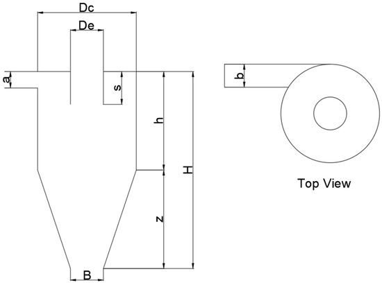
Figure 1.
Tangential inlet counterflow cyclone geometric parameters.
The mathematical models used to predict cyclone separation efficiency are generally based on two principles, called “equilibrium-orbit” and “time-of-flight”; however, hybrid models also exist, in which these two principles are used together. The equilibrium orbit model approach considers the imaginary cylindrical surface formed by continuing the vortex finder diameter (denoted by CS) to the cyclone base. This approach is based on the force balance of a particle rotating on the CS. The centrifugal force, which is related to the weight of the particles, acts on the particles on the CS, while the drag force acts towards the inner part. Therefore, large particles move from the CS towards the cyclone wall. In contrast, fine particles move towards the inner part, are included in the inner vortex moving towards the cyclone top and are discharged through the return pipe [33].
The particles on the CS where these two forces are in equilibrium determine the critical diameter (dcr); in other words, the particle size at which the two forces are in equilibrium is the critical diameter [33]. Examples of equilibrium orbit models are those described by Barth, Iozia and Leith, and Muschelknautz.
In the time-of-flight modeling approach, the time required for a particle in a radial position at the cyclone inlet to reach the cyclone wall and the time required for the particle to reach the cyclone bottom are taken into account. In this approach, a particle must reach the cyclone wall to be retained (i.e., it needs time to reach the cyclone wall). If a particle reaches the cyclone bottom before reaching the cyclone wall, then the particle will be ejected without being retained [34]. In the time-of-flight approach, the critical diameter is the smallest particle diameter that can pass half the inlet width distance before reaching the cyclone bottom [33]. Another mathematical model approach used to determine the efficiency of cyclone separators involves the use of hybrid models, in which the two model approaches mentioned above are used together.
One of the most widely used models is the Lapple model, which is based on the time-of-flight principle, where the size of particles that can pass the inlet half-width distance during the time they spend in the cyclone is defined as the critical diameter [35]. In the Barth model, which considers the balance of centrifugal and drag forces, the collection efficiency for any particle size is expressed as the ratio of the settling velocity of the particle to the terminal settling velocity. The critical diameter can be calculated by taking the efficiency expression as 50% in the Barth efficiency equation [36]. The Iozia and Leith model provides an empirical expression for fractional efficiency and is based on the Lapple and Barth models [9,37]. The Leith and Licht model was developed by assuming that the concentration in the cyclone is uniformly distributed in the radial direction [38]. Clift et al. [39] reconstructed the fractional efficiency equation based on the assumptions of Leith and Licht theory in their proposed model. The Muschelknautz model, an improved form of the Barth model, includes some additional parameters in the calculation, in addition to the other models. In the model, the surface roughness of the cyclone separator material and the wall roughness effects caused by the collected solids are taken into account. In addition, the effects of particle load and changes in the particle size distribution are also included in the model calculations [40,41,42]. The Li and Wang model, which includes particle splash and turbulent diffusion on the cyclone wall, provides a two-dimensional analytical expression for the particle distribution in the cyclone [43]. The Avci and Karagoz model was more based on a time-of-flight approach. It considers flow parameters, particle properties, geometric parameters, and a friction factor [44]. Apart from the models mentioned above, many other models exist in the literature. For this study, ten mathematical models that are frequently used in the literature were considered, which are detailed in Table 2. No fitting process was performed on the models used in the study. In other words, the models are used as they are available in the reference sources given. This is to show the sensitivity of the current state of the models to the different parameters specified.

Table 2.
The considered mathematical models and equations used for their calculation.
3. Results and Discussion
In this section, we proportionally evaluate the calculation results of the mathematical models, with respect to the experimental results. The point emphasized here is how the proportional change in the experimental critical diameter gives results in the models. The parameters analyzed are evaluated under separate headings.
When analyzing the effects of the parameters, the first value is taken as a reference, while the other values are given as a ratio of this value. For example, when analyzing the effect of the change in velocity on the critical diameter, the change is expressed as:
yvi = Vi/V1,
yd50,i = d50,i/d50,1.
The obtained experimental and calculated proportional values are compared, and absolute and squared error tables are also presented, in order to determine how much the calculated proportional values deviate from the experimental values.
3.1. The Effect of Inlet Velocity
One of the critical operating parameters affecting cyclone performance is the inlet velocity of the cyclone, which also defines the flow rate. There have been many experimental studies considering cyclones of different geometries and sizes. In these cyclones, the effects of other parameters have been reduced by considering the rate of change, rather than the absolute value, of the critical diameter. In this way, the response of the models to the velocity was analyzed.
It is generally known that cyclone efficiency increases with increasing inlet velocity in cyclone separators (i.e., the critical diameter value decreases). However, this situation may vary, depending on the change in the flow regime. Again, the order of the effect of velocity may also differ. In the models used for calculation, in general, the critical diameter varies in a manner inversely proportional to the square root of the inlet velocity. The models of Barth, Leith and Licht, Iozia and Leith, Lapple, Li and Wang, Sproull, and Clift et al. can be counted in this context. As the friction factor was considered to be constant in these models, there is no additional effect on the critical diameter with a change in the inlet velocity. On the other hand, in the models of Avci and Karagoz, Muschelknautz, and Moore and McFarland, the friction factor was calculated depending on the velocity, and an additional effect occurs due to this change. As the inlet velocity changes, the Reynolds number—and, therefore, the friction factor—change. In models that consider this, the critical diameter presents an additional change. The definition of the Reynolds number and its relationship with the friction loss factor in the flow in cyclone separators was also a significant problem.
The critical diameter values were calculated using the mathematical models, and the critical diameter values determined experimentally were calculated proportionally, according to the rate of change of the inlet velocity. The results are shown in Figure 2. A comparison of the performance of the mathematical models under variation in the inlet velocity is shown in Table 3.
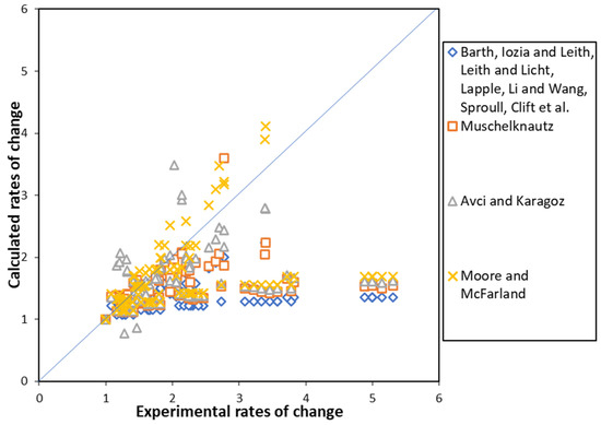
Figure 2.
Comparison of the critical diameter ratio calculated by mathematical models with the experimental critical diameter ratio under variation in inlet velocity [48].

Table 3.
Performance comparison of mathematical models under variation in inlet velocity.
This figure uses 126 experimental values for different velocities in different cyclones. The points where the experimental and mathematical model results are consistent with the velocity change are indicated by the line. According to these results, the critical diameter generally changes faster than the square root of the velocity ratio. As the change in the critical diameter is small at low velocity ratios, the calculated and experimental data gave close results, while the deviation increased when the ratios increased. In this respect, the critical diameter changes with the square root of the change in the velocity ratio in the models that do not consider the additional effect. Meanwhile, the fit was better in the models that take into account the additional effect. In these models—especially in the experimental data taken from Zhu and Lee [12]—there was a sudden decrease in the experimental critical diameter at speeds around 25 m/s. This sudden change could not be predicted by the models, and there is insufficient data in the literature to confirm this sudden change. As such, this is an unusual situation. Otherwise, the agreement was generally reasonable.
The inlet Re number was used as another evaluation criterion. The deviation of the model ratio from the experimental ratio with the input Re number was calculated, and the results are given in Figure 3. According to these results, in cyclones with Re numbers above 10,000, the model predictions were in better agreement with the experimental data, while the deviation increased at low Re numbers. This can occur in regions where the flow regime changes and shifts to laminar. In this region, the relationship between the Re number and the friction loss coefficient should be more compatible and defined accordingly. As such, the friction loss coefficient–Re number relationship can be re-defined for small Re numbers. In addition, model selection should be considered carefully when predicting in this region.
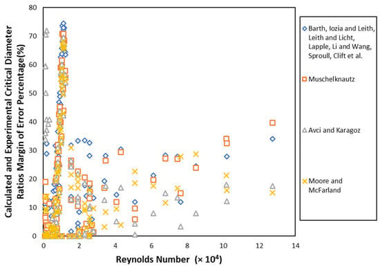
Figure 3.
Calculated and experimental critical diameter ratios margin of error percentage under variation in Reynolds number [48].
3.2. Effect of Vortex Finder Diameter and Length
The vortex finder diameter and length are essential geometric parameters in cyclone separators, and numerous experimental studies have investigated the effects of these parameters. Here, a cylindrical vortex finder geometry was considered, emphasizing the two main dimensions of diameter and plunge distance (length). A change in the shape of the cyclone vortex finder affects the tangential and axial velocity inside the cyclone. As a consequence, the pressure drop and collection efficiency are affected. This is not taken into account in the study.
First, the effect of the vortex finder diameter was investigated. For this purpose, the experimental data of Lim et al. [17], Kim and Lee [13], Iozia and Leith [9], Moore and McFarland [14], Hoekstra [15], and Hsiao et al. [16] were used. The results are shown in Figure 4. As can be seen from the figure, serious deviations occurred, especially regarding the model of Li and Wang.
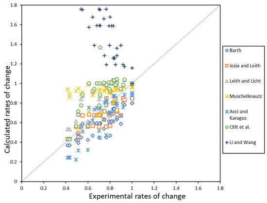
Figure 4.
Comparison of critical diameter ratio calculated with mathematical models and experimental critical diameter ratio under variation in vortex finder diameter (De).
When the critical diameter values calculated with mathematical models were examined, it was found that the critical diameter value increased with the increase in the De value with the models of Barth, Iozia and Leith, Leith and Licht, Muschelknautz, and Avci and Karagöz. Meanwhile, the critical diameter values remained constant in the Lapple, Moore and McFarland, and Sproull models, and even decreased with the increase in diameter in the model of Li and Wang. Table 4 indicates that the Iozia and Leith model was the best predictor of the experimental critical diameter change rate, according to the change in De.

Table 4.
Performance comparison of mathematical models under variation in vortex finder diameter.
Although the models generally showed similar trends, as can be seen from the figure above, some models showed different trends in some studies, when considered on the basis of experimental work. In this sense, the model calculations using the data of Hsiao et al. [16] were examined; the change in critical diameter with the change in De is shown in Figure 5. Looking at the figure, it can be seen that there was a decreasing trend in the critical diameter with an increase in De for the first three De values in the models of Leith and Licht and Clift et al., followed by an increasing trend after this point. In addition, for the model of Muschelknautz, the critical diameter can be seen to decrease after increasing up to the fourth De value.
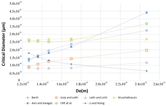
Figure 5.
Critical diameter values calculated under variation in De.
Furthermore, in the calculation conducted using the data taken from the experimental study of Moore and McFarland [14], it can be seen that there was a significant increase in the experimental critical diameter value compared to the calculated critical diameter value, especially at the last De value, for the model of Avci and Karagoz (Figure 6). It can be understood, from these results, that the smallest critical diameter (or the highest efficiency) can be reached at a specific value of the vortex finder diameter. For vortex finder diameters above this value, the critical diameter decreases while the diameter decreases. In the other region, the opposite happens. The considered models can approximately predict this region.
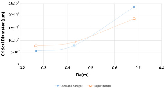
Figure 6.
Critical diameter values calculated under variation in De.
Another parameter affecting cyclone efficiency is the vortex finder length (Figure 7). Experimental data (Hsiao et al. [16]; Kim et al. [10]; Zhu and Lee [12]) were used to determine the prediction efficiency of the models. Looking at the experimental results from these studies, the critical diameter generally increases up to a specific value with increasing s value, and then decreases. In other words, within the framework of these data, there is a critical plunge distance value that gives the best efficiency in cyclone separators. If the s value is below or above this value in cyclone design, the cyclone efficiency will be negatively affected. When compared with the experimental studies, the models presented different behaviors. In this respect, the three studies were evaluated separately.
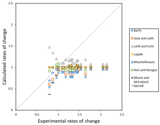
Figure 7.
Comparison of the critical diameter ratio calculated by mathematical models and the experimental critical diameter ratio under variation in the vortex finder length (s).
In the study of Zhu and Lee [12], experimental critical diameter values are given for three different s values (15.2, 30.5, and 45.7 mm) for six different inlet velocities. In our calculation results with the mathematical models, the models of Barth and Clift et al. predicted the optimal critical diameter value at the same s value as in the experimental data. With the models of Iozia and Leith, Muschelknautz, and Avci and Karagoz, the critical diameter value increased with increasing s value. For the model of Leith and Licht model, it was observed that the critical diameter value decreased with increasing s value. With the models of Lapple, Moore and McFarland, Sproull, and Li and Wang, it was observed that the change in s did not affect the critical diameter.
In the study of Hsiao et al. [16], experimental results were given for five different s values. Here, as in other studies, the optimal critical diameter value was observed. Looking at the mathematical model calculations, the only model that predicted the optimum s value in this study was the model of Avci and Karagöz. With the models of Barth, Iozia and Leith, Muschelknautz, and Clift et al., the critical diameter value increased continuously with the s value. In the Leith and Licht model, an increase in s caused a decrease in the critical diameter. In the models of Lapple, Moore and McFarland, Sproull, and Li and Wang, the change in s did not affect the critical diameter.
Looking at the data from these three experimental studies, it can be seen that an optimal efficiency value was obtained in all of them; in other words, the efficiency increases up to a certain point with an increase in the value of s. After this point, a further increase in the value of s will cause the efficiency to decrease. The mathematical models that followed this mechanism were those of Barth, Clift et al., and Avci and Karagoz. In other models, the change in s value either had no effect on the critical diameter or tended to lead to continuous increases or decreases. From Table 5, it can be seen that the Leith and Licht model was the best model, in terms of predicting the experimental critical diameter value proportionally with the change in the s value.

Table 5.
Performance comparison of mathematical models under variation in the vortex finder length.
3.3. Effect of Cyclone Length
One of the most important geometric parameters in a cyclone separator is the cyclone length, which is the sum of the lengths of the cylindrical and conical parts. Therefore, the proportions of these parts are also effective parameters. On the other hand, if the vortex formed is smaller than the cyclone length, the cyclone length has no effect. Furthermore, the behaviors of small and large cyclones are different. Therefore, this parameter is open to multi-faceted evaluation. Experimental studies have mainly been carried out by extending the cylindrical or conical part. In this respect, it was deemed more appropriate to make an evaluation based on the experimental studies. In their study, Hoffmann et al. [21] examined the change in cyclone performance by increasing the cyclone length through increasing that of the cyclone cylindrical part. According to the results of their study, while increasing the length, the efficiency increases up to a specific value and then decreases. Therefore, the smallest critical diameter can be obtained at a certain length. Zhu and Lee [12] confirmed this result in their experimental study.
The results of the experimental study examining the effect of the cyclone length, according to the change in the cylinder body, and the model calculation results are given in Figure 8. Performance comparison of mathematical models under variation in the cyclone length (conical part is constant, cylinder part length varies) is presented in the Table 6.
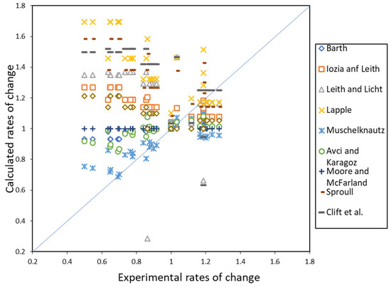
Figure 8.
Comparison of the critical diameter ratio calculated with mathematical models and the experimental critical diameter ratio under variation in the cyclone length (conical part is constant, cylinder part length varies).

Table 6.
Performance comparison of mathematical models under variation in the cyclone length (conical part is constant, cylinder part length varies).
When the experimental critical diameter values of Zhu and Lee [12] were examined, we found that the lowest critical diameter value was obtained at a cyclone length value of H = 12.2 cm. It can be seen that the critical diameter value increased at smaller and larger cyclone sizes than this value. In this sense, when the model calculations were analyzed, it can be seen that the models of Avci and Karagoz, and Barth predicted this point at the same size. In other words, with these two models, the calculated smallest critical diameter value was observed at the same cyclone size. In the models of Iozia and Leith, Leith and Licht, Lapple, Sproull, Clift et al., and Li and Wang, the critical diameter value decreased continuously with increasing cyclone size. In the Muschelknautz model, this value increased with an increase in cyclone length. In contrast, with the Moore and McFarland model, the change in cyclone length did not cause any change in the calculation and a constant result was obtained for each value. According to this information, the Avci and Karagoz, and Barth models predicted the most relevant result. In other models, a continuous increase or decrease in yield with this change, or no effect, was observed. In the experimental data of Hoffmann et al. [21], experimental critical diameter values were given for seven different cyclone lengths, ranging between 0.67 and 1.37 m. In these values, it can be found that, while the critical diameter values decreased with an increase in cyclone length from 0.67 to 1.07 m, the critical diameter values increased with an increase in cyclone length after this value. In other words, it can be said that the most efficient cyclone length for the experimental study is 1.07 m. In the mathematical model calculations, the smallest critical diameter value was obtained as 1.07 m only in the Barth model, while the lowest critical diameter value was obtained as 1.27 m in the Muschelknautz and Avci and Karagöz models. In the models of Clift et al. and Leith and Licht, the lowest critical diameter value was obtained as 0.87 m. Meanwhile, the models of Iozia and Leith, Lapple, and Sproull showed a continuous decrease in critical diameter with an increase in cyclone length and, on the other hand, in the models of Moore and McFarland and Li and Wang, the change in cyclone length did not result in any change in the critical diameter value. Therefore, it can be seen that the Barth model best captured the experimental critical diameter turning point (i.e., the point at which the efficiency drops sharply).
The results of the experimental study and model calculation, regarding the cyclone length obtained when changing the length of the conical part of the cyclone, are given in Figure 9. The results of the experimental studies conducted by Hsiao et al. [16], Saltzman and Hochstrasser [22], and Yang et al. [23] were used here. Performance comparison of mathematical models under variation in the cyclone length (cylindrical part is constant, conical part length varies) is presented in the Table 7.
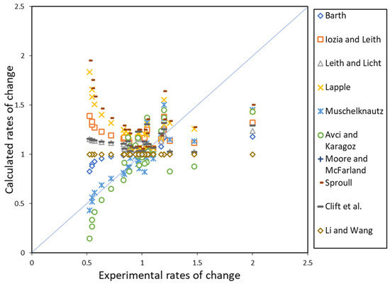
Figure 9.
Comparison of the critical diameter ratio calculated by mathematical models and the experimental critical diameter ratio under variation in the cyclone length (cylindrical part is constant, conical part length varies).

Table 7.
Performance comparison of mathematical models under variation in the cyclone length (cylindrical part is constant, conical part length varies).
In their study, Hsiao et al. [16] gave critical diameter values for ten different cyclone lengths between 0.0875 and 0.39 m. Looking at the experimental critical diameter values given, it can be seen that the critical diameter value increased with an increase in the length of the cyclone conical part.
This increasing trend was also observed in the models of Muschelknautz and Avci and Karagöz. To the contrary, for the models of Iozia and Leith, Leith and Licht, Lapple, Clift et al., and Sproull, it can be seen that the critical diameter decreased with an increase in the length of the cyclone conical part. In the Barth model, the critical diameter decreased with an increase in cyclone length up to 0.1 m, then continued to increase with an increase in length after this value. In other words, a turning point occurred in the Barth model. In the other two models included in the calculation—that is, the Moore and McFarland and Li and Wang models—the change in length did not cause any change in the critical diameter.
According to the experimental critical diameter values given by Saltzman and Hochstrasser [22] for lengths of 0.04287, 0.05239, and 0.0762 m, the smallest critical diameter value was 0.05239 m. Larger critical diameter values were obtained for sizes below and above this value. In the calculations, the Avci and Karagöz model was the only model in which we observed the smallest critical diameter value at this value. In the Muschelknautz model, there was a continuous increase in the critical diameter with an increase in length. In contrast, a continuous decrease was observed for the other models, except for that of Moore and McFarland.
Yang et al. [23] examined different cyclone lengths for KA values of 3, 5.5, and 8. Looking at the experimental critical diameter values given for cyclone lengths of 1.1, 1.658, 1.844, and 2.03 m at KA = 3, the critical diameter value decreased with an increase in cyclone length up to 1.844 m, then tended to increase after this value. Although this turning point was not captured by any model, this value was calculated as 1.658 m in the Barth model. In the models of Clift et al., Iozia and Leith, Leith and Licht, Lapple, Muschelknautz, and Sproull, there was a continuous decrease in the critical diameter with increasing length; while, in the Avci and Karagöz model, a continuously increasing trend was observed. In the experimental data taken at KA = 5.5, the turning point was 0.914, and this value was observed only in the Barth model. In the other models (except for those of Moore and McFarland and Li and Wang), it was found that the calculated critical diameter value decreased continuously with an increase in cyclone length. The turning point for the experimental critical diameter values at KA = 8 was 0.542 m. In this range, no turning point was observed in any model. The critical diameter value decreased as the cyclone length increased for all models, except those of Moore and McFarland and Li and Wang.
3.4. Effect of Temperature
Temperature is one of the essential operating parameters affecting cyclone performance, variations of which are commonly encountered in many different applications. It is crucial in this respect. Fluid pressure or density were evaluated together, as an increase in temperature affects the fluid viscosity and density and generally decreases the efficiency.
Experimental and numerical studies have shown that the cyclone separation efficiency decreases with increasing operating temperature in cyclone separators [18,19,20,49,50,51,52].
To assess the effect of temperature, the results of the experimental studies by Bohnet [18], Parker et al. [20], and Patterson and Munz [19] were used. The experimental critical diameter values increased with increasing temperature in the data used, and all models predicted this increasing trend. However, there were differences in the rates of change. Although the critical diameter values calculated at different temperature values in the models of Barth, Iozia and Leith, Lapple, Sproull, and Clift et al. differed, it was observed that the rates of change were the same for all of them, as the change in temperature affects the critical diameter value in direct proportion to the square root of the viscosity of the gas; in other words, these models reacted to temperature change in the same way. The comparison of the experimental critical diameter change rate with temperature and the calculated critical diameter rates is shown in Figure 10. According to the data in Table 8 regarding the proportional prediction ability, the models of Muschelknautz, Leith and Licht, and Moore and McFarland performed the best, in terms of predicting the effect of temperature changes.
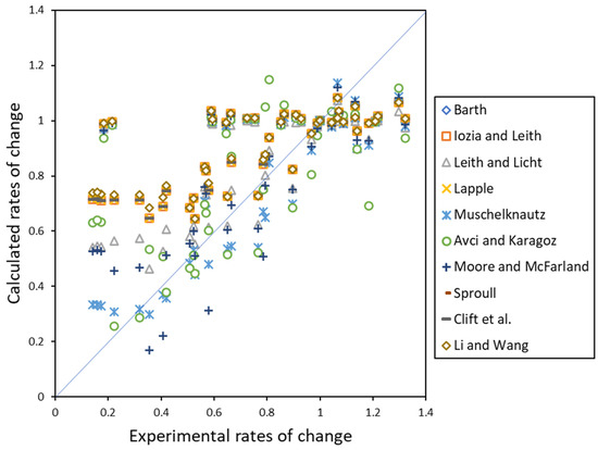
Figure 10.
Comparison of critical diameter ratio calculated by mathematical models and experimental critical diameter ratio under variation in temperature.

Table 8.
Performance comparison of mathematical models under variation in temperature.
3.5. Effect of Cone Tip Diameter
The cone tip diameter is one of the geometric parameters of the cyclone, which should be considered together with the cone length. The effect of fixed-length cone tip diameter tends to increase the efficiency and pressure losses in experimental studies, and it can be said that it is less effective than other parameters.
Xiang et al. [4] experimentally studied the effect on the critical diameter at three different flow rates in cyclones with three different cone tip diameters. In the study of Hsiao et al. [16] (the other study reviewed here), experimental critical diameter values were presented for five cone tip diameters. Figure 11 shows the rate of change of the experimental critical diameter values obtained in cyclones with different B values and the rate of change of the critical diameter calculated using the mathematical models. It can be seen that the change in B value did not lead to any change in the calculated critical diameter in the models of Iozia and Leith, Lapple, Moore and McFarland, and Li and Wang. As the B parameter is not included in the equations of the Lapple, Moore and McFarland, and Li and Wang models, it is expected that the change in the cone tip diameter should not affect the critical diameter. In the Iozia and Leith model, the choice between two different equations to be used in calculating the natural vortex length, Zc, is determined by whether the cone tip diameter (B) is larger or smaller than the central axis diameter (dc). If B is greater than dc, the cone tip value does not affect the calculation in the equation used; otherwise, the value of B affects the calculation of the natural vortex length. In the experimental data of Xiang et al. [4], which we examined here, the change in cone tip diameter did not cause any change in the critical diameter, as B > dc for all values. In the data of Hsiao et al. [16], there was a difference in the calculation, as when the cone tip diameter was 0.004 m, its value was less than dc. Only this value was calculated differently for the five cone tip diameters found here. In contrast, the other B values were calculated in the same way, as they were larger than dc. When calculating the critical diameter in the Barth model, the B value being greater or less than the De value affects the critical diameter calculation, as it changes the calculation of the hm value. In this model, if the De value is less than or equal to the cone tip diameter, the B value does not affect the calculation. To the contrary, in the data of Hsiao et al. [16], it was found that the critical diameter value decreased with an increase in the cone tip diameter (De > B) in the value range between 0.004 and 0.0125 m for the cone tip. In the models of Leith and Licht, Sproull, and Clift et al., the change in critical diameter had the opposite effect, compared to the experimental results. In other words, according to the results of the experimental studies, the critical diameter value decreased as the cone tip diameter decreased, while the critical diameter value increased in these three models. The Leith and Licht model and Clift et al. model (which is an improved version of the former model) gave worse results than the other models. In the Muschelknautz and Avci and Karagöz models, it was observed that the critical diameter value decreased with a decrease in the diameter of the cone tip, in accordance with the experimental study results. The trends of these two models were also in accordance with the experimental results, and the Avci and Karagöz model predicted the experimental rate of change of the cone tip diameter more closely. In particular, the inclusion of parameters for the conical part in the Avci and Karagöz model and the separate calculation for conical cyclones in the Muschelknautz model had a positive effect on the results obtained using these models. According to Table 9, it is seen that the best prediction of the experimental critical diameter change rate for the cone tip diameter variation is Avci and Karagoz model.
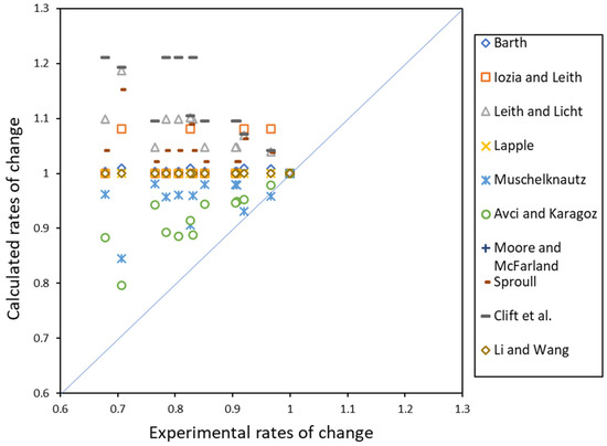
Figure 11.
Comparison of the critical diameter ratio calculated by mathematical models and the experimental critical diameter ratio under variation in the cone tip diameter (B).

Table 9.
Performance comparison of mathematical models under variation in the cone tip diameter.
3.6. Effect of Cyclone Diameter
Next, we discuss the proportional response of the models to variation in the cyclone diameter. The experimental data of Moore and McFarland [14], Dirgo and Leith [7], and Zhu and Lee [12] were used for this evaluation, which indicated that the critical diameter value increases with increasing cyclone diameter (Figure 12). This change was found to be the same in all model calculations. Although the increase in cyclone diameter was predicted to increase the critical diameter by all models, the rates of change differed. In this sense, conclusions can be drawn by looking at Table 10, which provides the mean absolute error and mean absolute squared error values for the rates of change. According to the mean absolute error values, the first three models that made the best predictions were those of Leith and Licht, Clift et al., and Iozia and Leith, respectively.
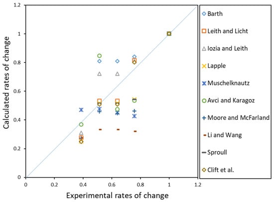
Figure 12.
Comparison of critical diameter ratio calculated by mathematical models and experimental critical diameter ratio under variation in cyclone body diameter (Dc).

Table 10.
Performance comparison of mathematical models under variation in cyclone body diameter.
3.7. Effect of Cyclone Inlet Cross-Section
The cyclone inlet cross-section is one of the most critical parameters affecting the performance of a cyclone separator. The inlet can have different shapes where a circular or rectangular inlet is most commonly used. Furthermore, it can also have different geometries. Therefore, besides the size of the cross-section, the edge ratios are also important if the cross-section is rectangular. In this respect, it is necessary to consider both cases.
As such, another important parameter affecting the performance of a cyclone separator is the inlet geometry. The inlet hydraulic diameter and geometric shape are two important parameters when analyzing the effect of the inlet geometry. In their experimental study, Hsiao et al. [16] investigated the effect of inlet geometry by keeping the aspect ratio (a/b) constant and varying the inlet area, as well as keeping the inlet area constant and varying the aspect ratio. The results of this study indicated that the critical diameter value increased with increasing inlet area (due to decreasing inlet velocity). This result was also confirmed in the studies conducted by Iozia and Leith [9] and Yang et al. [23]. As an increase in the inlet area directly affects the inlet velocity, this effect on the critical diameter is an expected result. Considering the a/b ratio—which is the other issue examined in the study of Hsiao et al. [16]—it can be seen that the general trend is that the critical diameter decreases with a decrease in this ratio. Here, it is also important which of the a or b values is changed when changing the a/b ratio. Hsiao et al. [16] stated that decreasing the b value may bring the particles closer to the cyclone wall, thus increasing the possibility of particle accumulation on the wall. In the experimental data given by Iozia and Leith [9], the critical diameter value increased with an increase in the b value while keeping the a value constant, and the critical diameter value also increased with an increase in the a value while keeping the b value constant.
In the following, we discuss how the mathematical models responded to variation in the inlet hydraulic diameter, rather than the inlet geometry. In this sense, the experimental data of Iozia and Leith [9] and Yang et al. [23] were used. Looking at the experimental critical diameter values presented in the study of Iozia and Leith [9], it can be seen that the critical diameter values increased with an increase in the hydraulic diameter. This trend was the same for all models used in the calculation. In the data taken from this study, the inlet velocity changes with the change in the inlet cross-section. In the study of Yang et al. [23], the inlet hydraulic diameter changed, but the inlet velocity was kept constant in all experimental tests. Keeping the inlet speed constant (i.e., changing only the inlet hydraulic diameter) produced different responses in the models, compared to the other study. In this context, the experimental critical diameter value increased with an increase in the inlet hydraulic diameter. However, this increase was less than that observed regarding the result of Iozia and Leith [9]. This increase was similar with the models of Barth, Leith and Licht, Lapple, Muschelknautz, Avci and Karagoz, Sproull, and Clift et al., and was observed to have a very small rate with the model of Moore and McFarland. On the other hand, in the models of Iozia and Leith and Li and Wang, the calculated critical diameter values decreased in the opposite direction to the experimental values with an increase in hydraulic diameter. The top three models most closely predicting the experimental critical diameter change rates were those of Li and Wang, Barth, and Moore and McFarland, respectively (Table 11). Comparison of critical diameter ratio calculated by mathematical models and experimental critical diameter ratio under variation in inlet cross-section is presented in the Figure 13.

Table 11.
Performance comparison of mathematical models under variation in inlet cross-section.
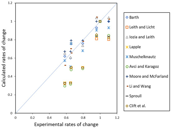
Figure 13.
Comparison of critical diameter ratio calculated by mathematical models and experimental critical diameter ratio under variation in inlet cross-section.
3.8. General Evaluation
In the evaluations above, the critical diameters calculated by the mathematical models for cyclone separators were examined proportionally for the determined parameters, with the aim of determining the proportional closeness of the solution of the changes of these parameters using the mathematical models to the experimental results. Next, all of the data used in the study were evaluated in absolute terms, and the closeness of the critical diameter values calculated by the models to the critical diameter values given in the experimental studies was determined. For this study, approximately 400 experimental data from 29 studies available in the literature were used. All experimental data were included in the comparison detailed in this section. The experimental data used are provided in Table 1. The values that are close to the line shown in Figure 14 can be said to indicate the models predicting the critical diameter with low error. In addition, in Table 12, the absolute error and absolute squared error values are given separately for the considered mathematical models. From the table, it can be seen that the models of Avci and Karagoz, Iozia and Leith, and Barth had the best prediction ability, regarding absolute error with respect to the experimental data. In terms of absolute squared error values, the best results were obtained using the models of Avci and Karagoz, Barth, and Lapple. The evaluation described here is a general evaluation for tangential inlet counterflow cyclones with many different cyclone geometries and operating parameters. As mentioned in the previous sections, it was observed that some models gave better or worse results when examining the variation in certain parameters.
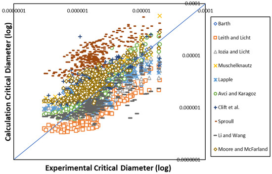
Figure 14.
Proximity of calculated critical diameter value and experimental critical diameter values (logarithmic).

Table 12.
Performance comparison of mathematical models in absolute terms for all data.
4. Conclusions
As there are many parameters affecting the performance of cyclone separators, some of which are ignored in relevant mathematical models, it is very difficult to accurately predict the actual value (i.e., experimental value). In our parametric investigations, a given model may respond sensitively to the variation in one parameter, while not being sensitive to the variation in another parameter. In this sense, when the results of the parametric analysis performed in this study were examined, the following models were determined to provide the best prediction performance, with regard to the respective parameters:
- -
- The Moore and McFarland model for inlet velocity change;
- -
- The Iozia and Leith model for De (vortex finder diameter) variation;
- -
- The Leith and Licht model for s (vortex finder length) variation;
- -
- The Muschelknautz model for cyclone length (with conical part constant) variation;
- -
- The Muschelknautz model for cyclone length (with cylindrical part constant) variation;
- -
- The Muschelknautz model for temperature variation;
- -
- The Avci and Karagoz model for cone tip diameter variation;
- -
- The Leith and Licht model for cyclone diameter variation; and
- -
- The Li and Wang model for inlet cross-section variation.
The best model in the general evaluation results was that of Avci and Karagoz (see Table 12). In addition to all of these results, certain factors (e.g., large or small cyclone, different flow regimes, and different Reynolds numbers) may further affect the predictive capability of these models.
Considering the fact that there are at least 12 independent parameters (geometrical and operating parameters) in cyclones, that they are related to flow regimes, and in addition to this, the scale effect, measurement accuracy in experimental data, limited experimental studies, differences in experimental conditions, it can be said that it is impossible for mathematical models to fully meet them. In other words, it is expected that the models deviate. Although this field is still open to development, it is also clear that it is difficult to produce a complete solution. What is done in this study is to show the sensitivity of the models depending on the parameters despite these difficulties. These evaluations are limited to the experimental data obtained.
Although the models are open to improvement and are not very accurate at present, they provide important ideas regarding the performance of cyclone separators. It can be concluded that, when carrying out model selection, attention should be paid to how the parameter whose change is examined is included in the calculation method of the model. The absolute error values given in the general evaluation section provide us with a general idea regarding the used data set. However, it is still difficult to say that one model is better than another from a parametric point of view. The development of classification systems (e.g., regarding the use of different mathematical models for different cyclones or different models for different operating conditions) may facilitate reaching more accurate results in specific scenarios.
Author Contributions
Conceptualization, A.A. and A.G.M.; methodology, A.G.M. and A.A.; software, A.G.M.; validation, A.G.M. and A.A.; formal analysis, A.G.M. and A.A.; investigation, A.G.M. and A.A.; resources, A.G.M. and A.A.; data curation, A.G.M. and A.A.; writing—original draft preparation, A.G.M.; writing—review and editing, A.A. and A.G.M.; visualization, A.G.M.; supervision, A.A. All authors have read and agreed to the published version of the manuscript.
Funding
This research received no external funding.
Data Availability Statement
All data generated or analyzed during this study are included in published article.
Conflicts of Interest
The authors declare no conflict of interest.
References
- Park, D.; Go, J.S. Design of cyclone separator critical diameter model based on machine learning and CFD. Processes 2020, 8, 1521. [Google Scholar] [CrossRef]
- Yang, Z.M.; He, Y.X.; Xiang, Q.; Zio, E.; He, L.M.; Luo, X.M.; Su, H.; Wang, J.; Zhang, J.J. Gas liquid cylindrical cyclone flow regime identification using machine learning combined with experimental mechanism explanation. Pet. Sci. 2023, 20, 540–558. [Google Scholar] [CrossRef]
- Elsayed, K.; Lacor, C. Modeling and Pareto optimization of gas cyclone separator performance using RBF type artificial neural networks and genetic algorithms. Powder Technol. 2012, 217, 84–99. [Google Scholar] [CrossRef]
- Xiang, R.; Park, S.H.; Lee, K.W. Effects of cone dimension on cyclone performance. J. Aerosol Sci. 2001, 32, 549–561. [Google Scholar] [CrossRef]
- Ji, Z.; Xiong, Z.; Wu, X.; Chen, H.; Wu, H. Experimental investigations on a cyclone separator performance at an extremely low particle concentration. Powder Technol. 2009, 191, 254–259. [Google Scholar] [CrossRef]
- Beeckmans, J.M.; Kim, C.J. Analysis of the efficiency of reverse flow cyclones. Can. J. Chem. Eng. 1977, 55, 640–643. [Google Scholar] [CrossRef]
- Dirgo, J.; Leith, D. Cyclone collection efficiency: Comparison of experimental results with theoretical predictions. Aerosol Sci. Technol. 1985, 4, 401–415. [Google Scholar] [CrossRef]
- Huang, A.N.; Maeda, N.; Shibata, D.; Fukasawa, T.; Yoshida, H.; Kuo, H.P.; Fukui, K. Influence of a laminarizer at the inlet on the classification performance of a cyclone separator. Sep. Purif. Technol. 2017, 174, 408–416. [Google Scholar] [CrossRef]
- Iozia, D.L.; Leith, D. The logistic function and cyclone fractional efficiency. Aerosol Sci. Technol. 1990, 6826, 598–606. [Google Scholar] [CrossRef]
- Kim, G.N.; Choi, W.K.; Jung, C.H. The development and performance evaluation of a cyclone train for the removal of contaminated hot particulate in a hot cell. Sep. Purif. Technol. 2007, 55, 313–320. [Google Scholar] [CrossRef]
- Moore, M.E.; McFarland, A.R. Design of stairmand-type sampling cyclones. Am. Ind. Hyg. Assoc. J. 1990, 51, 151–159. [Google Scholar] [CrossRef]
- Zhu, Y.; Lee, K.W. Experimental study on small cyclones operating at high flowrates. J. Aerosol Sci. 1999, 30, 1303–1315. [Google Scholar] [CrossRef]
- Kim, J.C.; Lee, K.W. Experimental study of particle collection by small cyclones. Aerosol Sci. Technol. 1990, 12, 1003–1015. [Google Scholar] [CrossRef]
- Moore, M.E.; McFarland, A.R. Performance modeling of single-inlet aerosol sampling cyclones. Environ. Sci. Technol. 1993, 27, 1842–1848. [Google Scholar] [CrossRef]
- Hoekstra, A.J. Gas Flow Field and Collection Efficiency of Cyclone Separators. Ph.D. Thesis, Delft University of Technology, Delft, The Netherlands, 2000. [Google Scholar]
- Hsiao, T.C.; Huang, S.H.; Hsu, C.W.; Chen, C.C.; Chang, P.K. Effects of the geometric configuration on cyclone performance. J. Aerosol Sci. 2015, 86, 1–12. [Google Scholar] [CrossRef]
- Lim, K.S.; Kim, H.S.; Lee, K.W. Characteristics of the collection efficiency for a cyclone with different vortex finder shapes. J. Aerosol Sci. 2004, 35, 743–754. [Google Scholar] [CrossRef]
- Bohnet, M. Influence of the gas temperature on the separation efficiency of aerocyclones. Chem. Eng. Process. Process Intensif. 1995, 34, 151–156. [Google Scholar] [CrossRef]
- Patterson, P.A.; Munz, R.J. Cyclone collection efficiencies at very high temperatures. Can. J. Chem. Eng. 1989, 67, 321–328. [Google Scholar] [CrossRef]
- Parker, R.; Jain, R.; Calvert, S.; Drehmel, D.; Abbott, J. Particle collection in cyclones at high temperature and high pressure. Environ. Sci. Technol. 1981, 15, 451–458. [Google Scholar] [CrossRef]
- Hoffmann, A.C.; de Groot, M.; Peng, W.; Dries, H.W.A.; Kater, J. Advantages and risks in increasing cyclone separator length. AIChE J. 2001, 47, 2452–2460. [Google Scholar] [CrossRef]
- Saltzman, B.E.; Hochstrasser, J.M. Design and performance of miniature cyclones for respirable aerosol sampling. Environ. Sci. Technol. 1983, 17, 418–424. [Google Scholar] [CrossRef] [PubMed]
- Yang, J.; Sun, G.; Gao, C. Effect of the inlet dimensions on the maximum-efficiency cyclone height. Sep. Purif. Technol. 2013, 105, 15–23. [Google Scholar] [CrossRef]
- Hoffmann, A.C.; van Santen, A.; Allen, R.W.K.; Clift, R. Effects of geometry and solid loading on the performance of gas cyclones. Powder Technol. 1992, 70, 83–91. [Google Scholar] [CrossRef]
- Kenny, L.C.; Gussman, R.A. Characterization and modelling of a family of cyclone aerosol preseparators. J. Aerosol Sci. 1997, 28, 677–688. [Google Scholar] [CrossRef]
- Kim, H.T.; Zhu, Y.; Hinds, W.C.; Lee, K.W. Experimental study of small virtual cyclones as particle concentrators. J. Aerosol Sci. 2002, 33, 721–733. [Google Scholar] [CrossRef]
- Yoshida, H.; Kwan-Sik, Y.; Fukui, K.; Akiyama, S.; Taniguchi, S. Effect of apex cone height on particle classification performance of a cyclone separator. Adv. Powder Technol. 2003, 14, 263–278. [Google Scholar] [CrossRef]
- Zhao, B.; Shen, H.; Kang, Y. Development of a symmetrical spiral inlet to improve cyclone separator performance. Powder Technol. 2004, 145, 47–50. [Google Scholar] [CrossRef]
- Qian, F.; Zhang, J.; Zhang, M. Effects of the prolonged vertical tube on the separation performance of a cyclone. J. Hazard. Mater. 2006, 136, 822–829. [Google Scholar] [CrossRef]
- Sakura, G.B.; Leung, A.Y.T. Experimental study of particle collection efficiency of cylindrical inlet type cyclone separator. Int. J. Environ. Sci. Dev. 2015, 6, 160–164. [Google Scholar] [CrossRef]
- Masoumeh, M.; Shuran, L.; Qinzhen, Z.; Guanle, D.; Zhen, L.; Keping, Y. Performance evaluation of a new micro gas cyclone using simulation and experimental studies to capture indoor fine particles. Adv. Powder Technol. 2019, 30, 1151–1159. [Google Scholar] [CrossRef]
- Lim, J.H.; Park, S.I.; Lee, H.J.; Zahir, M.Z.; Yook, S.J. Performance evaluation of a tangential cyclone separator with additional inlets on the cone section. Powder Technol. 2020, 359, 118–125. [Google Scholar] [CrossRef]
- Hoffmann, A.C.; Stein, L.E. Gas Cyclones and Swirl Tubes: Principles, Design and Operation, 2nd ed.; Springer: Berlin/Heidelberg, Germany, 2008; ISBN 978-3-540-74694-2. [Google Scholar]
- Leith, D.; Jones, D.L. Cyclones. In Handbook of Powder Science and Technology, 2nd ed.; Fayed, M.E., Otten, L., Eds.; Chapman and Hall: New York, NY, USA; pp. 727–752.
- Lapple, C.E. Processes use many collection types. Chem. Eng. 1951, 58, 144–151. [Google Scholar]
- Barth, W. Design and layout of the cyclone separator on the basis of new investigations. Brennst Warme Kraft 1956, 8, 9. [Google Scholar]
- Iozia, D.L.; Leith, D. Effect of cyclone dimensions on gas flow pattern and collection efficiency. Aerosol Sci. Technol. 1989, 10, 491–500. [Google Scholar] [CrossRef]
- Leith, D.; Licht, W. The collection efficiency of cyclone type particle collectors—A new theoretical approach. Air Pollut. Control AlChE Symp. Ser. 1972, 68, 196–206. [Google Scholar]
- Clift, R.; Ghadiri, M.; Hoffman, A.C. A critique of two models for cyclone performance. AIChE J. 1991, 37, 285–289. [Google Scholar] [CrossRef]
- Muschelknautz, E. Die Berechnung von zyklonabscheidern für gase. Chem. Ing. Tech. 1972, 44, 63–71. [Google Scholar] [CrossRef]
- Muschelknautz, E.; Trefz, M. Design and Calculation of Higher and Highest Loaded Gas Cyclones. In Proceedings of the Second World Congress on Particle Technology, Kyoto, Japan, 12–22 September 1990. [Google Scholar]
- Muschelknautz, E.; Trefz, M. Druckverlust und abscheidegrad in zyklonen. VDI Wärmeatlas 1991, 6 Auflage, Lj1–Lj2. [Google Scholar]
- Enliang, L.; Yingmin, W. A new collection theory of cyclone separators. AIChE J. 1989, 35, 666–669. [Google Scholar] [CrossRef]
- Avci, A.; Karagoz, I. Effects of flow and geometrical parameters on the collection efficiency in cyclone separators. J. Aerosol Sci. 2003, 34, 937–955. [Google Scholar] [CrossRef]
- Caliskan, M.E.; Karagoz, I.; Avci, A.; Surmen, A. Investigation into the effects of various parameters on the performance and classification potential of a cyclone classifier. Powder Technol. 2019, 356, 102–111. [Google Scholar] [CrossRef]
- Avci, A.; Karagoz, I. A new explicit friction factor formula for laminar, transition and turbulent flows in smooth and rough pipes. Eur. J. Mech. B Fluids 2019, 78, 182–187. [Google Scholar] [CrossRef]
- Sproull, W.T. Air Pollution and Its Control, 1st ed.; Exposition Press Inc.: New York, NY, USA, 1970. [Google Scholar]
- Mumcu, A.; Avcı, A. Siklon ayırıcılarda kritik çap tahmini için kullanılan matematik modellerin giriş hızı değişiminde davranışlarının incelenmesi. Acad. Perspect. Procedia 2021, 4, 212–222. [Google Scholar] [CrossRef]
- Bohnet, M.; Lorenz, T. Separation efficiency and pressure drop of cyclones at high temperatures. In Gas Cleaning at High Temperature, 1st ed.; Clift, R., Seville, J.P.K., Eds.; Springer: Dordrecht, The Netherlands, 1993; pp. 17–31. ISBN 978-94-011-2172-9. [Google Scholar]
- Gimbun, J.; Choong, T.S.Y.; Fakhru’l–Razi, A.; Chuah, T.G. Prediction of the effect of dimension, particle density, temperature, and inlet velocity on cyclone collection efficiency. J. Teknol. 2004, 40, 37–50. [Google Scholar] [CrossRef]
- Li, W.; Chen, J. Experimental research on cyclone performance at high temperature. Front. Mech. Eng. China 2007, 2, 310–317. [Google Scholar] [CrossRef]
- Wan, G.; Sun, G.; Gao, C.; Dong, R.; Zheng, Y.; Shi, M. Modeling the gas flow in a cyclone separator at different temperature and pressure. Front. Chem. Sci. Eng. 2010, 4, 498–505. [Google Scholar] [CrossRef]
Disclaimer/Publisher’s Note: The statements, opinions and data contained in all publications are solely those of the individual author(s) and contributor(s) and not of MDPI and/or the editor(s). MDPI and/or the editor(s) disclaim responsibility for any injury to people or property resulting from any ideas, methods, instructions or products referred to in the content. |
© 2023 by the authors. Licensee MDPI, Basel, Switzerland. This article is an open access article distributed under the terms and conditions of the Creative Commons Attribution (CC BY) license (https://creativecommons.org/licenses/by/4.0/).