Abstract
To recover dimethyl sulfoxide, an organic solvent nanofiltration membrane is prepared via the interfacial polymerization method. N-Phenylthiourea (NP)is applied as a water-soluble monomer, reacted with trimesoyl chloride (TMC) on the polyetherimide substrate crosslinked by ethylenediamine. The results of attenuated total reflectance-fourier transform infrared spectroscopy and X-ray electron spectroscopy confirm that N-Phenylthiourea reacts with TMC. The membrane morphology is investigated through atomic force microscopy and scanning electronic microscopy, respectively. The resultant optimized TFC membranes NF-1NP exhibited stable permeance of about 4.3 L m−2 h−1 bar-1 and rejection of 97% for crystal violet (407.98 g mol−1) during a 36 h continuous separation operation. It was also found that the NF-1NP membrane has the highest rejection rate in dimethyl sulfoxide (DMSO), and the rejection rates in methanol, acetone, tetrahydrofuran, ethyl acetate and dimethylacetamide(DMAc) are 51%, 84%, 94%, 96% and 92% respectively. The maximum flux in the methanol system is 11 L m−2 h−1 bar−1, while that in acetone, tetrahydrofuran, ethyl acetate and DMAc is 4.3 L m−2 h−1 bar−1, 6.3 L m−2 h−1 bar−1, 3.2 L m−2 h−1 bar−1, 4.9 L m−2 h−1 bar−1 and 2.1 L m−2 h−1 bar−1, respectively. It was also found that the membrane prepared by N-Phenylthiourea containing aromatic groups has lower mobility and stronger solvent resistance than that of by thiosemicarbazide.
1. Introduction
As a kind of membrane technology, nanofiltration technology not only has the common characteristics of membrane technology such as low operating pressure, low energy consumption, no phase change in the separation process, green and environmental protection, but also has unique nano-scale pore structure, charged membrane surface, selective separation of salt ions and other properties. It is increasingly widely used in the fields of seawater desalination, biomedicine, the food industry, petrochemical and other fields [1,2,3]. The application of nanofiltration membranes has also gradually developed from conventional aqueous solution systems to more demanding applications such as organic solvent systems [3,4,5]. The solvent-resistant nanofiltration was first developed by Surirajan in 1964, using cellulose acetate membrane to separate liquid hydrocarbon mixtures. With the need of separating organic solvent systems, solvent-resistant membranes have been more and more used, such as solvent recovery, catalyst regeneration, antibiotic separation, manufacture of drugs, edible oils and chemical products and so on [6,7,8]. As an important reaction solvent, DMSO can be used as a dyeing solvent, dye remover, dyeing carrier for synthetic fibers and absorbent for recovering acetylene and sulfur dioxide. For instance, the total amount of waste printed circuit boards (WPCBs) heaps up to million tons yearly, with a 5–10% annual increase predicted. DMSO is used to delaminate WPCBs to recycle the mixture of glass fiber, copper foil and anthracene oil [9]. At present, the recovery of DMSO mainly adopts the method of vacuum distillation, which has high energy consumption. It is necessary to use more energy-saving and environment-friendly separation technology, such as organic solvent nanofiltration (OSN) technology to realize the recovery of DMSO.
The preparation methods of solvent-resistant composite nanofiltration membranes are various, including the coating method, the layer-by-layer self-assembly method, the phase conversion method, and interfacial polymerization [10,11,12,13]. Composite nanofiltration membrane is used to cover a layer of a functional toplayer based on nanofiltration membrane (NF). Its main structure is a support layer—a reinforced composite layer, which provides dense network support for the membrane, and the reinforced composite membrane plays a vital physical and chemical structure. The structure of different support layers and reinforced composite layers can provide different separation performance. The key to the optimization of solvent-resistant composite nanofiltration membranes is the selection of their preparation methods and raw materials.
The most common preparation methods for OSN membranes include interfacial polymerization, layer by layer self-assembly. Recently, more novel methods such as incorporating nano-material (Metal-organic Framework (MOFs), covalent organic polymer (COPs), zeolite imidazolium ester framework structural material (ZIFs) and TiO2) into the selective layer and vacuum deposition are emerging [14,15,16,17,18,19,20]. To improve the solvent resistance of polyamide composite nanofiltration membranes, especially for polar solvents, researchers have carried out a lot of exploration and research, and made various modifications to polyamide composite nanofiltration membranes to obtain membranes with good solvent resistance For instance, Yang et al. synthesized a thin-film composite (TFC) OSN membrane by applying trihydroxytriphenylmethane to react with TMC by the interfacial polymerization (IP) technique, the prepared composite membrane showed a molecular weight cut-off of 295 Da with methanol permeance up to 5.86 L m−2 h−1 bar−1 [21].
So far, the preparation of TFC OSN membrane, to maintain high permeance and rejection, is still the focus of research. More reports focus on the doping treatment of porous materials in the membrane’s surface or support layer, aiming at adjusting the pore structure of the membrane. To reduce the influence of the trade-off effect, covalent organic frameworks were chosen as interlayers. For instance, Li et al. prepared an OSN membrane using 1,3,5-triformylphloroglucinol and hydrazine on a polyimide substrate before the IP. The prepared membrane exhibited an ethanol permeance of 6.34 L m−2 h−1 bar−1, a Rhodamine B (479.01 Da) rejection of 99% [22]. Lin et al. prepared an OSN membrane with silica nanochannels on an anodic aluminum oxide. The prepared membrane has a 99% rejection of Evans blue (960.8 Da) in acetone [23]. Shi et al. developed an OSN membrane by depositing an ultra-thin Teflon AF2400 membrane on top of a polyester (PE)substrate. The prepared membrane has a Molecular Weight Cut Off(MWCO) of 150 Da and shows permeance of 3–8 L m−2 h−1 bar−1 for ethyl acetate, toluene and hexane [24]. Gao et al. developed a novel membrane via plasma grafting of polyethylene glycol (PEG) on the substrate. The prepared membrane has a permeance of 5.91 L m−2 h−1 bar−1 and rejection of Rose Bengal (1017.64 Da) of 99.64% in isopropanol [25]. All these methods are aimed at preparing OSN membranes that can perform well in different organic solvents.
Aromatic amines and non-aromatic amines are widely used to prepare polyamide solvent-resistant membrane materials, while there are few reports on whether aromatic thioureas with similar structures can be prepared solvent-resistant membrane materials. Li et al. reported that thiourea is easily covalently linked with aromatic polymers by adding m-phenylenediamine (MPD) to react with TMC [26]. Inspired by their research, N-Phenylthiourea, a cheap diamine is used to synthesize an OSN membrane to explore the possibility of being an aqueous monomer as shown in Scheme 1. Attenuated total reflectance-fourier transform infrared spectroscopy (ATR-FTIR) and X-ray electron spectroscopy (XPS) characterization results show that N-Phenylthiourea reacts with TMC and the membrane NF-NP shows a stable performance in DMSO during the long-term experiment. We also choose thiosemicarbazide as a monomer for TFC membrane preparation to compare with the membrane material prepared by NP to explore the influence of monomer structure on membrane performance.
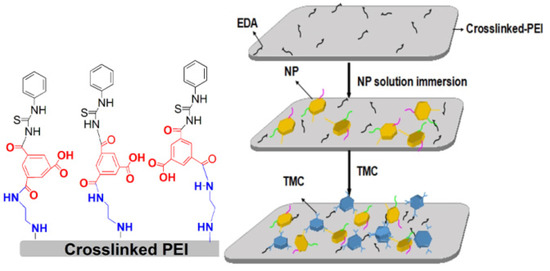
Scheme 1.
Interfacial polymerization mechanism of N-Phenylthiourea reacting with TMC.
2. Materials and Methods
2.1. Materials
Polyetherimide (Ultem 1000) was purchased from Saudi Basic Industries Corporation (Saudi Arabia). N-Phenylthiourea (CAS: 103-85-5, 98%analyticalpurity) Thiosemicarbazide (CAS: 79-19-6) Trimesoyl chloride (CAS: 4422-95-1, 98%analyticalpurity) were purchased from Heowns (Tianjin, China). Polypropylene non-woven fabric waspurchased from TEDA Filters Co., Ltd. (Tianjin, China). N,N-Dimethylacetamide (DMAc) (CAS:127-19-5, 99%analyticalpurity)and Dimethyl sulfoxide(CAS:67-68-5, 98%analyticalpurity)were supplied by Xilong (Guangzhou, China). 4-Dimethylaminopyridine (CAS:1122-58-3, 99%analyticalpurity) was supplied by Macklin (Shanghai, China). Crystal Violet (CAS: 548-62-9, 98%analyticalpurity)was purchased from Yuanye Bio-Technology (Shanghai, China). Erythrosin B (CAS:16423-68-0, 99%analyticalpurity) was purchased from Huibang Bio-Technology (Xian, China). Congo Red (CAS:16423-68-0, 99%analyticalpurity) was purchased from Pules Bio-Technology (Nantong, China). RoseBengal (CAS: 632-69-9, 95%analyticalpurity) was purchased from Maokang Bio-Technology (Shanghai, China). Ethylenediamine (CAS:107-15-3, 99.5%Chromatographic purity) was purchased from Union Chemical (Nanjing, China). And all the above chemicals are used as received without further purification.
2.2. Membrane Preparation
2.2.1. Polyetherimide Substrate and Crosslinked Membrane
A 23% polyetherimide (PEI) solution is stirred and dissolved in DMAc at 60 °C for 4 h. Then, the mixed solution is scraped on the smooth surface of PP non-woven fabric, and the distance between the scraper and the non-woven fabric is 150 μm. The PEI substrate can be enhanced by the introduction of EDA. Pour 100 mL of 6% ethylenediamine(EDA) methanol solution (w/v) onto the surface of the PEI membrane for crosslinking for 1 h, and then clean the membrane surface with methanol.
2.2.2. Thin Film Composite Membranes
First, a certain concentration of N-phenylthiourea solution is poured onto the surface of the PEI membrane and left for 10 min. Then pour on the mixture of TMC and hexane with a mass volume ratio of 0.2 (w/v). The time for interfacial polymerization is 10 min, and then the microwave heating film with the frequency of 2450 MHz for 1 min is used as the post-treatment method. The prepared membrane is named NF-XNP, where X represents the concentration of N-Phenylthiourea. For comparison, The EDA crosslinked PEI membrane is named NF-J, while the NF-J membrane is directly poured onto TMC and named NF-C for comparison.
2.3. Characterization of the Membranes
Attenuated total reflectance-fourier transform infrared spectroscopy (ATR-FTIR) is used to characterize the membrane chemical structure. (Thermo Scientific, NICOLET 6700, Waltham, MA, USA). The scanning electron microscope (SEM) is used to characterize the surface and cross-section samples of the prepared membrane (Zeiss, sigma300, Obercohen, Germany). X-ray electron spectroscopy (Thermo Scientific ESCALAB 250XI, Waltham, MA, USA) characterizes the chemical composition of the membrane surface. The height image of atomic force microscopy (Seiko, SPA400, Tokyo Metropolitan, Japan) is used to characterize the morphology of the membrane surface. The static contact angle measuring instrument (Zhongchen, JC2000-D1, Shanghai, China) is used to characterize the hydrophilic/hydrophobic properties of membranes.
Calculate the permeance of the membrane according to Formula (1)
where P, V, A, t and ΔP represent the permeance (L m−2 h−1 bar−1, the permeate volume (L), the effective area of membrane (m2), time (h) and trans-membrane pressure (bar), respectively.
Calculate the rejection of the membrane according to Formula (2)
where R, and represent rejection, the concentrations of the permeated solution, and the feed solution, respectively.
The membrane swelling test is used to determine the chemical stability of the prepared membrane. First, cut the dried film into several pieces of size 1 cm × 3 cm, and then weigh the membrane separately. Then soak these dry membranes in several different organic solvents for 48 h. Then take out the membrane, wipe the solution on the membrane surface with filter paper, and weigh it. Calculate the swelling degree according to the following Formula (3)
3. Results
3.1. Morphologies
Figure 1 shows the SEM of composite membranes including NF-C, NF-0.5NP and NF-1NP. All membranes have asymmetrical cross-section structures with finger pores. and the surface of membranes is all rough, which may be caused by heat treatment after interfacial polymerization. As shown in Figure S1, the NF-J membrane, without IP reaction, has a smooth surface. Compared with the membrane prepared by N-Phynylthiourea, the surface morphology of the membrane, prepared by using 2,5-Dithiobiurea and thiosemicarbazide as the aqueous phase monomer, is more regular.
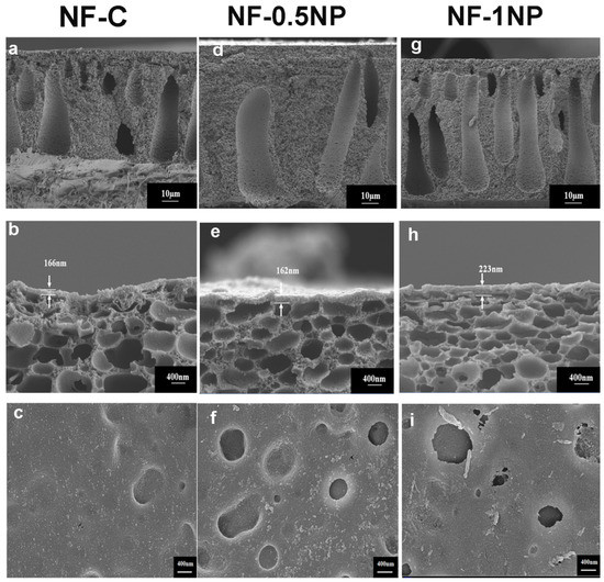
Figure 1.
SEM images of NF-C (a–c), NF-0.5NP (d–f) and NF-1NP (g–i) including the cross-section (a,d,g (magnified by 1000 times)) and (b,e,h (magnified by 20,000 times)). and surface (c,f,i (magnified by 20,000 times)).
Figure 2 displays the roughness of three membranes including NF-C, NF-0.5NP and NF-1NP, with the mean square roughness of 117 nm for NF-C, 120 nm for NF-0.5NP and 40 nm for NF-1NP. With the increase of NP concentration, a relatively dense structure is formed on the membrane surface, so the roughness is reduced.
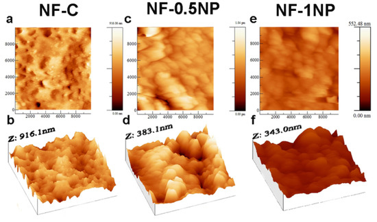
Figure 2.
AFM images of surfaces including NF-C (a,b), NF-0.5NP (c,d) andNF-1NP (e,f).
3.2. Chemical Structure Analysis
Figure 3 shows the ATR-IR spectra of composite membranes prepared through the IP between TMC and N-Phenylthiourea including NF-0.25NP, NF-0.5NP and NF-1NP as well as NF-C and NF-J. For the crosslinked PEI membrane NF-J, there are bands in 1775, 1720, and 1364 cm−1 (imide groups) [26,27,28], whereas for the NF-NP, a band at 1045 cm−1 corresponds to S=C. For the membranes that reacted with TMC including NF-0.25NP, NF-0.5NP and NF-1NP, there are bands at 1376 cm−1 and 1539 cm−1 (amide groups), indicating that NP reacts with TMC generating the polyamide and the S=C group [29,30]. According to the literature report, the absorption intensity ratio of the two peaks of the ATR spectrum can be calculated [27,28,31]. Through comparison, it is found that the intensity ratio of I 1376/I 1775 increases sequentially, NF-0.25NP (2.22) < NF-0.5NP (2.25) < NF-1NP (2.61). It’s illustrated that the number of amide groups on the membrane surface increases with the increase of NP concentration. For comparison, we prepared two membranes, namely NP-TMC for interfacial polymerization reaction on the support membrane and NP for membrane-only pouring NP on the support membrane. The incorporation of TMC can be seen from the ATR-FTIR spectrum, as shown in Figure S3, in which the carbonyl group belongs to amide at 1640 cm−1 [32]. The appearance of a new absorption peak at 1034 cm represents C-Cl stretching vibration [33], indicating that TMC has successfully reacted with NP on the toplayer by the IP method.
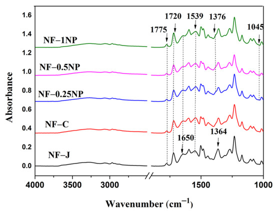
Figure 3.
ATR-FTIR spectra of the NF-J, NF-C, NF-0.75PNP, NF-1PNP, NF-1.25PNP and NF-1.5PNP membranes.
As shown in Figure 4, the deconvolution XPS spectra are used to analyze the elemental functional groups of the surface of membranes. for the membrane NF-1NP, there exists three N species including the-N-C=S- at 400.4 eV and Ph-NH- at 401.1 eV, whereas, for NF-C as shown in Figure S2, there are N species including N-C=O- (399.9 eV) and the CH-NH2-(399.5 eV), suggesting the occurrence of interfacial polymerization between TMC and the NP [34,35,36]. Meanwhile, the C-NH2 of unreacted amines disappeared suggesting that TMC also reacted with the terminal amino group [37].
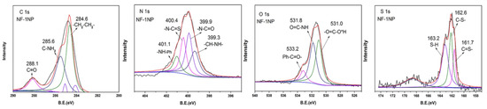
Figure 4.
C1s, N1s, O1s and S1sXPS spectra of NF-1NP.
As shown in Table 1, NF-C and C-PEI have three compositions including C, N, and O, with an individual content of 72%, 15%, 11% and 2% for C-PEI, and 68%, 16%, 13% and 3% for NF-C. For NF-1NP, it consists of four components including C, N, O and S. The interfacial polymerization between TMC and the terminal amino groups on the surface of C-PEI makes the cortex of NF-C have higher O content and lower C content than C-PEI.

Table 1.
The C, N and O compositions of the C-PEI, NF-C, and NF-1NP.
3.3. Membrane Performance
Figure 5 displays the effect of NP concentration on the performance of the nanofiltration membrane during interfacial polymerization. The composite nanofiltration membranes prepared with 0.25%, 0.5% and 1.0% (w/v) NP aqueous solutions are named NF-0.25NP, NF-0.5NP, and NF-1NP. NF-C is used as blank control, that is, only 0.2% (w/v) TMC n-hexane solution reacts with cross-linked PEI (C-PEI) membrane for interfacial polymerization. For the nanofiltration membrane, without NP participating in interfacial polymerization, the permeance of NF-C is 1.9 L m−2 h−1 bar−1, and the retention rate of 2 g L−1 CV is 62%. However, for the NP-TMC membrane, the permeance gradually increases from 2.74 to 4.3 L m−2 h−1 bar−1, while the CV rejection changes from 79 to 97.8%. When the concentration of NP solution is more than 1.0% (w/v), the flux is kept at 4.24 L m−2 h−1 bar−1, and the rejection is almost stable at 98%, indicating that the appropriate concentration of NP solution is 1.0%. For the interface polymerization reaction involving NP, a sufficient amount of TMC groups react with NP, so as to obtain an increase in rejection. However, when the NP concentration is greater than 1.25%, the NP is excessive, the formation of the cross-linked structure is limited, and the flux remains unchanged. However, the toplayer of the membrane, formed solely by the terminal amino groups on the surfaces that react with TMC, is mainly a linear structure, so the rejection of NF-C is relatively low.
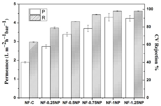
Figure 5.
The effects of NP concentration on the performance of membrane in DMSO.
As shown in Figure 6, the performance of NF-1NP membrane, in several solvents including methanol, DMSO, acetone, tetrahydrofuran, ethyl acetate and DMAc, is also studied. The membrane has the highest rejection rate in DMSO, and the rejection rates in methanol, acetone, tetrahydrofuran, ethyl acetate and DMAc are 51%, 84%, 94%, 96% and 92% respectively. The maximum flux in the methanol system is 11 L m−2 h−1 bar−1, while that in acetone, tetrahydrofuran, ethyl acetate and DMAc is 6.3 L m−2 h−1 bar−1, 3.2 L m−2 h−1 bar−1, 4.9 L m−2 h−1 bar−1 and 2.1 L m−2 h−1 bar−1, respectively. In different organic solvent systems, the membrane shows relatively large separation performance, which is mainly due to the difference in viscosity, polarity, and other properties of different solvents, resulting in the different relationship between the membrane and the solvent.
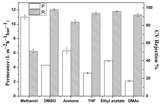
Figure 6.
The performance ofNF−1NP membrane in methanol, dimethyl sulfoxide, acetone, tetrahydrofuran, ethyl acetate and DMAc.
As shown in Figure 7, the swelling degree of NF-1NP in several solvents, including methanol, DMSO, acetone, tetrahydrofuran and ethyl acetate are much lower than that of other membranes, which indicates that the toplayer of the prepared membrane is critical to the chemical stability of the membrane. With the increase of NP, the chemical stability was gradually enhanced. The selection of membrane materials has a great influence on the performance of the solvent-resistant composite membrane prepared.
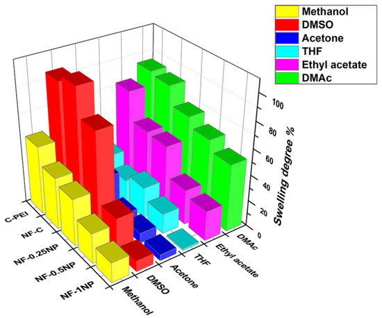
Figure 7.
The swelling degree of NF-1NP membrane, including methanol, dimethyl sulfoxide, acetone, tetrahydrofuran, ethyl acetate and DMAc.
Figure 8 displays the contact degree of the membrane including C-PEI, NF-C, NF-0.25NP, NF-0.5NP, NF-0.75NP and NF-1NP are 53.3°, 93.5°, 91.2°, 87.2°, 71.0°, and 55.1°. For C-PEI, there is a lot of hydrophilic end amino groups on the surface after being cross-linked by EDA. When TMC was poured on the surface of C-PEI, a hydrophobic structure was introduced, so the hydrophobicity of the membrane was enhanced. When NP is used as a monomer to participate in interfacial polymerization, it can be seen that the hydrophilicity of the membrane gradually increases with the addition of NP, which may be caused by the existence of amino groups in the NP structure.
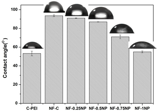
Figure 8.
The static water contact angles of NF-C, NF-0.25NP, NF-0.5NP, NF-0.75NP, and NF-1NP membranes.
The determination of MWCO and pore size distribution of nanofiltration membrane is achieved by filtration and separation of neutral organic molecules with different molecular weights, polyethylene glycol. During the experiment, under 0.2 MPa, PEG200, PEG300, PEG400 and PEG600 of 2.0 g L−1 were separated. The concentration of PEG was determined by UV vis. The calculation of the pore size distribution method was reported [38,39]. Figure 9 displays the pore size distribution of NF-1NP with an average pore diameter of 0.33 nm. TheNF-1NP also shows good separation performance for separating several dyes in the DMSO system, the rejection for separating methyl blue (373.86 Da) reaches 97%.
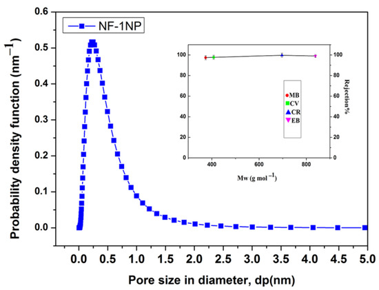
Figure 9.
Pore size distribution of NF-1NP and rejection of dyes including Methylene blue(MB, 373.86 Da), crystal violet(CV, 407.94 Da), Congo red(CR, 696.68 Da), and Erythrosin B (EB, 859.89 Da).
Long periods of exposure to organic solvents and continuous filtrations for NF-1NP are carried out. As shown in Figure 10, during the 36 h separation test, the NF-1NP membrane shows a stable rejection of approximately 97% with a permeance of 4.3 L m−2 h−1 bar−1. The above experiments show that the NF-1NP membranes have a chemical stability in DMSO.
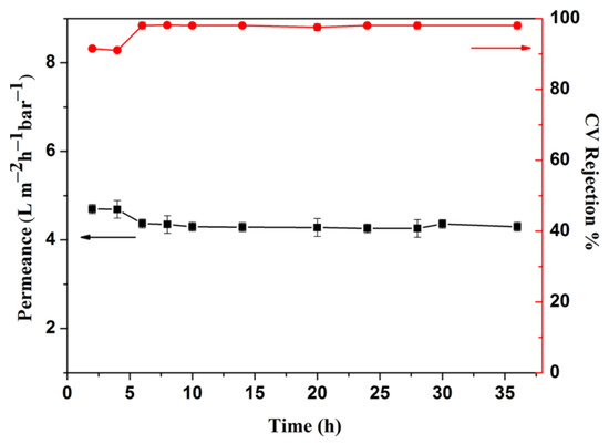
Figure 10.
The long-term stability test of NF-1NP in DMSO for 36 h.
Thiosemicarbazide (TZ) is used as a monomer, reacted with TMC, for TFC membrane preparation to compare with the membrane material prepared by NP, to explore the influence of monomer structure on membrane performance. Compared with NP, the thiosemicarbazide structure does not contain phenyl groups. As shown in Figure 11, the prepared membrane shows excellent nanofiltration properties in the water system with a CV rejection of 99%, however, it was interesting to note that the rejection for CV in DMSO is as low as 12%.The use of an aromatic ring (for NP) or straight chain carbon chain (for Thiosemicarbazide) inserted into the membrane surface, to form a relatively dense cross-linked structure, is an important feature of the preparation of composite membranes. These insertions may be the reason that can induce the formation of nanopore characteristics. Therefore, it can be concluded that the chemical structure of the membrane surface is an important factor in determining the solvent resistance of the membrane. B.V Bruggen et al. reported the stronger the solvent resistance of the membrane, the lower the mobility of the polymer chain in the top layer [40,41]. Compared with TB, the membrane material prepared by NP as a material containing aromatic groups has lower mobility and stronger solvent resistance.
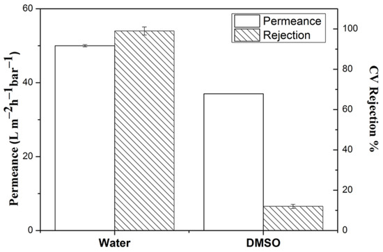
Figure 11.
The performance ofNF-1TZ membrane in Water and DMSO.
As shown in Figure 12, after the separation test of 36 h, the surface of the NF-NP membrane was cleaned by deionized water and re-separated again, the results show a flux of 3.9 L m−2 h−1 bar−1 and a stable rejection of 98%. The flux recovery ratio is 91% with a stable rejection of 98%after cleaning. The rejection has a little increase and the permeance shows a little decrease. The excellent antifouling performance may be attributed to the high hydrophilicity and relatively smooth membrane surface.
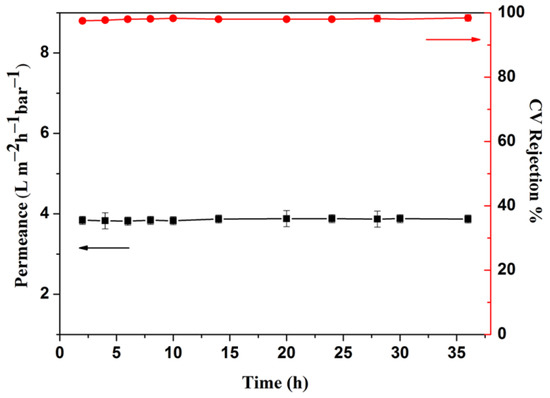
Figure 12.
The time-dependent antifouling evaluation of NF-1NP being cleaned in DMSO for 36 h.
The performance of membranes including lab-made membranes is widely compared as state-of-art in tabulated form in Table 2. For instance, Li et al. prepared a PMDA-MDA membrane using a gelation/non-solvent-induced phase separation method, which has a permeance of 6.3 L m−2 h−1 bar−1 and a stable rejection of 89.5% for RB [42]. Li et al. prepared polybenzimidazole membranes for organic solvent nanofiltration, the membrane has a permeance of 0.31 L m−2 h−1 bar−1 and a stable rejection of 40% for Sudan IV (380 Da) [43]. Aburabie et al. prepared silane-crosslinked asymmetric polythiosemicarbazide membranes totally rejecting direct red dye(MW 1373 g mol−1) with a permeance of 2.2 L m−2 h−1 bar−1 in DMSO [44]. Sun et al. prepared a polyamide membrane using electrospinning to produce polymer substrates with low tortuosity, the membrane has a permeance of 1 L m−2 h−1 bar−1 and a stable rejection of 90% for fast green FCF (808.91 g mol) [45]. Aburabie et al. prepared an OSN membrane using diaminopiperazine (DAP)as a monomer reacting with TMC, the membrane has a permeance of 2.2 L m−2 h−1 bar−1 and a rejection of 91% for Rose Bengal (1017.64 Da) [46]. Lu et al. prepared an OSN membrane using piperazine (PIP) reacting with TMC on the electrospun nanofiber substrates, the membrane has a permeance of 1.0 L m−2 h−1 bar−1 and a rejection of 90% for Fast Green FCF (808.85 Da) [33]. Compared with the above OSN membranes, the prepared membranes are comparable in performance.
Table 2.
Comparison between the reported separation performance of OSN membranes and this work.
4. Conclusions
In order to realize the effective recovery of dimethyl sulfoxide, an OSN membrane is prepared by N-Phenylthiourea containing a rigid group benzene ring. The optimized membrane NF-1NP has a rejection of 97.0% and permeance of 4.3 L m−2 h−1 bar−1 for CV in DMSO, respectively. The roughness of three membranes including NF-0.5NP and NF-1NP, with the mean square roughness of 120 nm for NF-0.5NP and 40 nm for NF-1NP.The NF-1NP membrane has the highest rejection rate in dimethyl sulfoxide (DMSO), and the rejection rate in methanol, acetone, tetrahydrofuran, ethyl acetate and DMAc are 51%, 84%, 94%, 96% and 92% respectively. We also made a comparative experiment with TPU without an aromatic group, which shows that the use of an aromatic ring (for NP) or straight chain carbon chain (for Thiosemicarbazide) inserted into the membrane surface to form a relatively dense cross-linked structure is an important feature of the preparation of composite membranes. The swelling degree of NF-1NP in several solvents, including methanol, DMSO, acetone, tetrahydrofuran and ethyl acetate, indicated that the chemical stability gradually enhanced with the increase of NP. Compared with the reported experimentally prepared membranes OSN membranes, the NP-TMC membranes are comparable in performance. The synthesized NF-1NP membrane shows stable performance in DMSO, providing a new way for the utilization of substances such as phenyl-thiourea.
Supplementary Materials
The following supporting information can be downloaded at: https://www.mdpi.com/article/10.3390/separations10030179/s1, Figure S1: SEM images of surface and cross section including NF-J; Figure S2: C1s, N1s, O1s and S1s XPS spectra of NF-C membranes; Figure S3: ATR-FTIR spectra of the NP-TMC and NP membranes.
Author Contributions
A.Z.: Conceptualization, Resources, Writing, Supervision, G.H.: Software, X.L.: Formal analysis, K.G. and M.Z.: Methodology. All authors have read and agreed to the published version of the manuscript.
Funding
This research was funded by the Natural Science key Project of Anhui Education Department. Grant Number: 2022AH051115.
Data Availability Statement
Data sharing is not applicable to this article.
Conflicts of Interest
The authors declare that there is no conflict of interest between researchers and public research results in this study.
References
- Shi, G.M.; Feng, Y.; Li, B.; Tham, H.; Lai, J.-Y.; Chung, T.-S. Recent progress of organic solvent nanofiltration membranes. Prog. Polym. Sci. 2021, 123, 101470. [Google Scholar] [CrossRef]
- Scharzec, B.; Holtkötter, J.; Bianga, J.; Dreimann, J.; Vogt, D.; Skiborowski, M. Conceptual study of co-product separation from catalyst-rich recycle streams in thermomorphic multiphase systems by OSN. Chem. Eng. Res. Des. 2020 157, 65–76. [CrossRef]
- Liu, G.; Jin, W. Pervaporation membrane materials: Recent trends and perspectives. J. Membr. Sci. 2021, 636, 119557. [Google Scholar] [CrossRef]
- Hadizade, G.; Binaeian, E.; Emami, M. Preparation and characterization of hexagonal mesoporous silica/polyacrylamide nanocomposite capsule (PAM-HMS) for dye removal from aqueous solutioxns. J. Mol. Liq. 2017, 238, 499–507. [Google Scholar] [CrossRef]
- Werth, K.; Kaupenjohann, P.; Skiborowski, M. The potential of organic solvent nanofiltration processes for oleochemical industry. Sep. Purif. Technol. 2017, 182, 185–196. [Google Scholar] [CrossRef]
- Zhao, Y.; Tong, T.; Wang, X.; Lin, S.; Reid, E.; Chen, Y. Differentiating Solutes with Precise Nanofiltration for Next Generation Environmental Separations: A Review. Environ. Sci. Technol. 2021, 55, 1359–1376. [Google Scholar] [CrossRef] [PubMed]
- Li, Y.; Guo, Z.; Li, S.; Van der Bruggen, B. Interfacially Polymerized Thin-Film Composite Membranes for Organic Solvent Nanofiltration. Adv. Mater. Interfaces 2020, 8, 2001671. [Google Scholar] [CrossRef]
- Vandezande, P.; Gevers, L.; Vankelecom, I. Solvent resistant nanofiltration: Separating on a molecular level. Chem. Soc. Rev. 2008, 37, 365–405. [Google Scholar] [CrossRef] [PubMed]
- Zhu, P.; Chen, Y.; Wang, L.Y.; Qian, R. A novel approach to separation of waste printed circuit boards using dimethyl sulfoxide. Int. J. Environ. Sci. Technol. 2013, 10, 175–180. [Google Scholar] [CrossRef]
- Feng, W.; Li, J.; Fang, C.; Zhang, L.; Zhu, L. Controllable thermal annealing of polyimide membranes for highly-precise organic solvent nanofiltration. J. Membr. Sci. 2022, 643, 120013. [Google Scholar] [CrossRef]
- Loh, X.X.; Sairam, M.; Bismarck, A.; Steinke, J.; Livingston, A.; Li, K. Crosslinked integrally skinned asymmetric polyaniline membranes for use in organic solvents. J. Membr. Sci. 2009, 326, 635–642. [Google Scholar] [CrossRef]
- Matthias, M.; Cédric, V.; Marloes, T.; Guy, K.; Vankelecom, I. Crosslinked PVDF-membranes for Solvent Resistant Nanofiltration. J. Membr. Sci. 2018, 566, 223–230. [Google Scholar]
- Chisca, S.; Duong, P.; Emwas, A.; Sougrat, R.; Nunes, S. Crosslinked copolyazoles with a zwitterionic structure for organic solvent resistant membranes. Polym. Chem. 2015, 6, 543–554. [Google Scholar] [CrossRef]
- Wang, X.; Wang, N.; Li, X.; An, Q.-F. A review of nano-confined composite membranes fabricated inside the porous support. Adv. Membr. 2021, 1, 100005. [Google Scholar] [CrossRef]
- Zhu, J.; Yuan, S.; Wang, J.; Zhang, Y.; Tian, M.; Van der Bruggen, B. Microporous organic polymer-based membranes for ultrafast molecular separations. Prog. Polym. Sci. 2020, 110, 101308. [Google Scholar] [CrossRef]
- Feng, Y.; Weber, M.; Maletzko, C.; Chung, T. Fabrication of organic solvent nanofiltration membranes via facile bioinspired one-step modification. Chem. Eng. Sci. 2019, 198, 74–84. [Google Scholar] [CrossRef]
- Zhang, H.; Mao, H.; Wang, J.; Ding, R.; Du, Z.; Liu, J.; Cao, S. Mineralization-inspired preparation of composite membranes with polyethyleneimine–nanoparticle hybrid active layer for solvent resistant nanofiltration. J. Membr. Sci. 2014, 470, 70–79. [Google Scholar] [CrossRef]
- Peyravi, M.; Jahanshahi, M.; Rahimpour, A.; Javadi, A.; Hajavi, S. Novel thin film nanocomposite membranes incorporated with functionalized TiO2 nanoparticles for organic solvent nanofiltration. Chem. Eng. J. 2014, 241, 155–166. [Google Scholar] [CrossRef]
- Farahani, M.D.A.; Hua, D.; Chung, T.-S. Cross-linked mixed matrix membranes (MMMs) consisting of amine-functionalized multi-walled carbon nanotubes and P84 polyimide for organic solvent nanofiltration (OSN) with enhanced flux. J. Membr. Sci. 2018, 548, 319–331. [Google Scholar] [CrossRef]
- Alduraiei, F.; Kumar, S.; Liu, J.; Nunes, S.; Szekely, G. Rapid fabrication of fluorinated covalent organic polymer membranes for organic solvent nanofiltration. J. Membr. Sci. 2022, 648, 120345. [Google Scholar] [CrossRef]
- Huang, Y.; Li, S.-L.; Fu, Z.; Gong, G.; Hu, Y. Preparation of microporous organic solvent nanofiltration (OSN) composite membrane from a novel tris-phenol monomer. Sep. Purif. Technol. 2022, 301, 121985. [Google Scholar] [CrossRef]
- Li, S.; Yang, F.; Liu, S.; Li, H.; Su, B.; Han, L.; Gao, X.; Gao, C. Effective regulating interfacial polymerization process of OSN membrane via in-situ constructed nano-porous interlayer of 2D TpHz covalent organic frameworks. J. Membr. Sci. 2023, 665, 121101. [Google Scholar] [CrossRef]
- Lin, G.-S.; Yang, J.; Mou, C.-Y.; Tung, K.-L. Realizing ultrathin silica membranes with straight-through channels for high-performance organic solvent nanofiltration (OSN). J. Membr. Sci. 2021, 627, 119224. [Google Scholar] [CrossRef]
- Shi, G.M.; Chung, T.-S. Teflon AF2400/polyethylene membranes for organic solvent nanofiltration (OSN). J. Membr. Sci. 2020, 602, 117972. [Google Scholar] [CrossRef]
- Gao, Z.; Shi, G.; Cui, Y.; Chung, T.-S. Organic solvent nanofiltration (OSN) membranes made from plasma grafting of polyethylene glycol on cross-linked polyimide ultrafiltration substrates. J. Membr. Sci. 2018, 565, 169–178. [Google Scholar] [CrossRef]
- Li, W.; Lou, L.; Hai, Y.; Fu, C.; Zhang, J. Polyamide thin film composite membrane using mixed amines of thiourea and m-phenylenediamine. RSC Adv. 2015, 5, 54125–54132. [Google Scholar] [CrossRef]
- Zhou, A.; Shi, C.; He, X.; Fu, Y.; Anjum, A.; Zhang, J.; Li, W. Polyarylester nanofiltration membrane prepared from monomers of vanillic alcohol and trimesoyl chloride. Sep. Purif. Technol. 2018, 193, 58–68. [Google Scholar] [CrossRef]
- Li, W.; Bian, C.; Fu, C.; Zhou, A.; Shi, C.; Zhang, J. A poly(amide-co-ester) nanofiltration membrane using monomers of glucose and trimesoyl chloride. J. Membr. Sci. 2016, 504, 185–195. [Google Scholar] [CrossRef]
- Tarboush, B.; Rana, D.; Matsuura, T.; Arafat, H.; Narbaitz, R. Preparation of thin-film-composite polyamide membranes for desalination using novel hydrophilic surface modifying macromolecules. J. Membr. Sci. 2008, 325, 166–175. [Google Scholar] [CrossRef]
- Zhou, A.; Li, L.; Li, M.; Chen, Q. Fabrication of Poly(amide-co-ester) Solvent Resistant Nanofiltration Membrane from P-nitrophenol and Trimethyl Chloride via Interfacial Polymerization. Separations 2022, 9, 28. [Google Scholar] [CrossRef]
- Lin, S.; Dence, C. Methods in Lignin Chemistry; Springer: Berlin/Heidelberg, Germany; New York, NY, USA, 1992. [Google Scholar]
- Ahmad, A.; Ooi, B. Properties–performance of thin film composites membrane: Study on trimesoyl chloride content and polymerization time. J. Membr. Sci. 2005, 255, 67–77. [Google Scholar] [CrossRef]
- Lu, T.-D.; Chen, B.-Z.; Wang, J.; Jia, T.-Z.; Cao, X.-L.; Wang, Y.; Xing, W.; Lau, C.; Sun, S.-P. Electrospun nanofiber substrates that enhance polar solvent separation from organic compounds in thin-film composites. J. Mater. Chem. A 2018, 6, 15047–15056. [Google Scholar] [CrossRef]
- Almijbilee, M.; Wu, X.; Zhou, A.; Zheng, X.; Cao, X.; Li, W. Polyetheramide organic solvent nanofiltration membrane prepared via an interfacial assembly and polymerization procedure. Sep. Purif. Technol. 2020, 234, 116033. [Google Scholar] [CrossRef]
- Wang, Y.; Gu, J.; Zhou, A.; Kong, A.; Almijbilee, M.A.; Zheng, X.; Zhang, J.; Li, W. Poly[acrylate-co-amide] network composite via photo polymerization for organic solvent nanofiltration separation. Sep. Purif. Technol. 2020, 246, 116855. [Google Scholar] [CrossRef]
- Zheng, X.; Zhou, A.; Wang, Y.; He, X.; Zhao, S.; Zhang, J.; Li, W. Modulating hydrophobicity of composite polyamide membranes to enhance the organic solvent nanofiltration. Sep. Purif. Technol. 2019, 223, 211–223. [Google Scholar] [CrossRef]
- Zhou, A.; Wang, Y.; Cheng, D.; Li, M.; Wang, L. Effective interfacially polymerized polyarylester solvent resistant nanofiltration membrane from liquefied walnut shell. Korean J. Chem. Eng. 2022, 39, 1566–1575. [Google Scholar] [CrossRef]
- Michaels, A.S. Analysis and Prediction of Sieving Curves for Ultrafiltration Membranes: A Universal Correlation? Sep. Sci. Technol. 1980, 15, 1305–1322. [Google Scholar] [CrossRef]
- Singh, S.; Khulbe, K.; Matsuura, T.; Ramamurthy, P. Membrane characterization by solute transport and atomic force microscopy. J. Membr. Sci. 1988, 142, 111–127. [Google Scholar] [CrossRef]
- Blumenschein, S.; Kätzel, U. An heuristic-based selection process for organic solvent nanofiltration membranes. Sep. Purif. Technol. 2017, 183, 83–95. [Google Scholar] [CrossRef]
- Van der Bruggen, B.; Jansen, J.; Figoli, A.; Geens, J.; Van Baelen, D.; Drioli, E.; Vandecasteele, C. Determination of parameters affecting transport in polymeric membranes: Parallels between pervaporation and nanofiltration. J. Phys. Chem. B 2004, 108, 13273–13279. [Google Scholar] [CrossRef]
- Li, Y.; Xue, J.; Zhang, X.; Cao, B.; Li, P. Formation of Macrovoid-Free PMDA-MDA Polyimide Membranes Using a Gelation/Non-Solvent-Induced Phase Separation Method for Organic Solvent Nanofiltration. Ind. Eng. Chem. Res. 2019, 58, 6712–6720. [Google Scholar] [CrossRef]
- Xing, D.Y.; Chan, S.; Chung, T.-S. The ionic liquid [EMIM]OAc as a solvent to fabricate stable polybenzimidazole membranes for organic solvent nanofiltration. Green Chem. 2014, 16, 1383–1392. [Google Scholar] [CrossRef]
- Aburabie, J.; Emwas, A.-H.; Peinemann, K.-V. Silane-Crosslinked Asymmetric Polythiosemicarbazide Membranes for Organic Solvent Nanofiltration. Macromol. Mater. Eng. 2019, 304, 1800551. [Google Scholar] [CrossRef]
- Sun, S.-P.; Chung, T.-S.; Lu, K.-J.; Chan, S.-Y. Enhancement of flux and solvent stability of Matrimid®thin-film composite membranes for organic solvent nanofiltration. AIChE J. 2014, 60, 3623–3633. [Google Scholar] [CrossRef]
- Aburabie, J.; Neelakanda, P.; Karunakaran, M.; Peinemann, K.-V. Thin-film composite crosslinked polythiosemicarbazide membranes for organic solvent nanofiltration (OSN). React. Funct. Polym. 2015, 86, 225–232. [Google Scholar] [CrossRef]


Disclaimer/Publisher’s Note: The statements, opinions and data contained in all publications are solely those of the individual author(s) and contributor(s) and not of MDPI and/or the editor(s). MDPI and/or the editor(s) disclaim responsibility for any injury to people or property resulting from any ideas, methods, instructions or products referred to in the content. |
© 2023 by the authors. Licensee MDPI, Basel, Switzerland. This article is an open access article distributed under the terms and conditions of the Creative Commons Attribution (CC BY) license (https://creativecommons.org/licenses/by/4.0/).