Abstract
Overflow pipes are important components of hydrocyclones. The overflow products can carry huge amounts of residual energy when being discharged. In order to take full advantage of the residual energy and enhance hydrocyclone separation performance, this research designed a novel hydrocyclone by adding static mixing units with spiral elements in the overflow pipe. This study performed numerical simulations to investigate the effects of the install position of the spiral structure on the separation performance and inner flow field of the hydrocyclone. It can be concluded that both tangential velocity and pressure are first enhanced and then reduced by the elevation of the spiral structure. When the spiral structure is installed 30 mm away from the overflow pipe bottom, because of the hindrance of spiral elements, the discharge of coarse particles with the overflow are fully decreased and the quality of overflow products are enhanced.
1. Introduction
There are many particles and suspended matter that are difficult to treat in sewage. Fine particles are not only the source of pollutants, but also the carrier of toxic and harmful substances [1,2,3]. Therefore, solving the problem of fine particle sewage pollution has become a global environmental problem. In order to solve this problem, many scholars use clarifier [4,5,6] to treat sewage, but the stirring and secondary precipitation in the dosing process not only increase the floor area but also increase the treatment time. As a solid–liquid separation device with the functions of sand removal and separation, a cyclone has the advantages of simple structure design, compact structure, no moving parts, small footprint and so on, and is widely used in the chemical industry, food, medical treatment, coal extraction, municipal sewage treatment and other fields [7,8,9,10,11,12,13,14]. However, in the process of cyclone separation, due to the existence of a solid boundary, part of the tangential velocity of the two-phase fluid fed into the cyclone is far less than that of the main flow area, so that the fluid flows through the top cover and moves downward along the outer wall of the overflow pipe, and finally attains confluence in the overflow port of the overflow pipe and is discharged. This part of the fluid carries coarse particles without separation, which is often called short-circuit flow, resulting in overflow running.
To address overflow and sewage treatment problems, many scholars have carried out different degrees of research on cyclones. Lv [15] applied this process to the separation of fine particles in wastewater treatment by constructing 300 parallel devices of miniature hydrocyclones. The study found that the average separation efficiency of miniature hydrocyclones in industrial treatment could reach 77.2%. Patra [16] used a ribbed hydrocyclone to treat fluorine in wastewater, and found that under the same geometric size and working conditions, the separation efficiencies of ribbed and conventional hydrocyclones were 93.5% and 80%, respectively, and ribbed hydrocyclone overflow particle size was significantly reduced. Li [17] studied the tangential velocity distribution characteristics under different cone angles, inlet size and feed flow of hydrocyclone, and concluded that tangential velocity could enhance centrifugal strength and thus improve separation efficiency. Yu [18] used a two-stage hydrocyclone separation system with two mini-hydrocyclones 8 mm in size in series to separate rice starch wastewater. The results showed 92.1% separation efficiency. Hwang [19] studied a hybrid system of hydrocyclone and dissolved gas flotation (DAF) device. When the flow rate was 15 m/h, the removal rate of T-P and CODcr in DAF reactor reached 98.3% and 85.3%, respectively.
In order to obtain the results required for exploration efficiently and accurately, computer numerical simulation technology has become a powerful means to simulate the separation performance and internal flow field properties of hydrocyclones [20,21,22,23,24,25,26,27]. Vysyaraju [28] used a modeling method of computational fluid dynamics (CFD), the Large Eddy Simulation wall of achievable k-ε and Revnolds Stress Model (RSM), and LES-Wale turbulence model was used for prediction. Numerical simulation results comply well with experimental data, verifying numerical simulation accuracy. Hou [29] used a TFM model to simulate different bottom flow tube structures and accurately obtained flow field distribution characteristics and particle distribution characteristics. Vega-Garcia [30] and Hou [31] conducted CFD simulation and verified it in combination with the test. By comparison, they found good agreement among the results, which verified the reliability of the CFD model.
Because the cyclone has short circuit flow, circulating flow and other flow field characteristics, overflow running is inevitable in the separation process. In order to solve this phenomenon, a new type of cyclone is proposed in this paper, which separates the mixed media through a cyclone separation function and uses fluid residual energy in the overflow tube to mix through the spiral overflow tube. In the current research, hydrocyclone internal flow field characteristics are studied with helical overflow pipe, and the fluid movement characteristics in the helical overflow pipe are captured by numerical simulation. Turbulent distribution characteristics and particle phase separation characteristics were obtained by RSM+TFM. The whole process adopts steady state simulation.
2. Mathematical Model and Mesh Generation
In this paper, in order to solve the problem of overflow running caused by short-circuit flow of hydrocyclone, a spiral structure is proposed from overflow pipe structure to correct the flow field change inside the hydrocyclone, so as to reduce the short-circuit flow and improve the quality of overflow products.
Figure 1 is the structural diagrams of five hydrocyclones. Solidworks (2020, Dassault Systemes) was used to establish 3D models. Table 1 contains the structural parameters of Φ75 mm hydrocyclone. The spiral structures were installed at 15, 30, 50, and 75 mm above the overflow pipe bottom, respectively. Figure 2 illustrates the dimensions of hydrocyclones and sizes of the spiral structures. Specifically, the four spiral structures were interlaced at an identical screw pitch of 30 mm and an intersection angle of 90°, and the number of the spiral was set as 0.5.
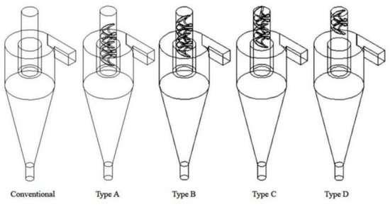
Figure 1.
Structure diagrams.

Table 1.
Structural parameters of Φ75 mm hydrocyclone.
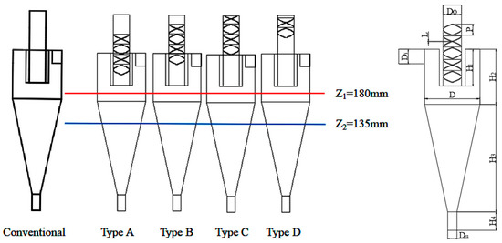
Figure 2.
Structure size.
Next, mesh generation was taken using the ANSYS-ICEM combination. The main body of the hydrocyclone was meshed by hexahedrons. The spiral structure was meshed by the means of tetrahedrons due to the large torsional resistance of the spiral structure. Meanwhile, we used denser meshes at the spiral overflow pipes to obtain weak flow at overflow pipe inner wall, as shown in Figure 3.
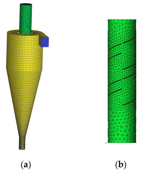
Figure 3.
Mesh generation: (a) Combination mesh; (b) Tetrahedrons mesh.
3. Model Description
In the current research, RSM model, VOF model and TFM model are used for the simulation of hydrocyclones. These models were comprehensively discussed in our previous works; hence, only the key parts of the models are listed here.
- (1)
- The RSM model
- (2)
- The VOF model
VOF free multiphase flow model is applied for modeling air–water interface in hydrocyclones. Interface tracking is done by solving continuity and momentum equations (Equations (2) and (3), respectively).
Here is phase volume fraction in computational cell.
- (3)
- The TFM model
Phase n averaged momentum and continuity equations are stated as
where is mixed phase average velocity, is mass transfer and is mixed phase density.
The equation of momentum conservation is
where is the kth phase density, is pressure, is mixed phase viscosity, is total phase number, is the relative slip velocity of kth and mixed phases and is volume force.
3.1. Simulation Parameters
Finite volume element method was applied to convert the governing equation into an algebraic equation. Double-precision was used for simulation. All governing equations, including the turbulent dissipation rate equation, turbulent kinetic energy equation, volume fraction equation and momentum equation used QUICK mode with third-order accuracy. Residual error was adjusted as 1 × 10⁻⁵. In this study, quartz sand materials with 2650 kg/m3 density were applied for performance verification and the total feed volume fraction distribution was 3.2%. The feed inlet was adjusted as velocity inlet at 5 m/s, and both underflow and overflow ports were considered as the pressure outlet. Underflow port backpressure was set as 0.045 MPa. The other wall surfaces all obeyed non-slip boundary conditions. During the simulation process, no backpressure was applied to the underflow of the conventional hydrocyclone. Table 2 shows volume fractions and size distributions of solid particles.

Table 2.
Size distributions and volume fractions of solid particles.
3.2. Mesh Independence Verification
The quality and number of meshes is an important factor affecting numerical accuracy. Therefore, the hydrocyclone was divided into meshes with the numbers of 245,718, 139,350, 87,768, 68,004 and 49,812, respectively. Figure 4 illustrates the results of hexahedral mesh generation. Mesh independence verification was conducted to achieve optimal simulation performance, as shown in Figure 4. When 87,768 meshes were generated, the velocity flow field was more symmetrical and stable, with a slight change of the tangential velocity. Considering mesh number effect on operation speed and simulation accuracy, the model with 87,768 meshes in the computational domain was selected for further numerical simulation.
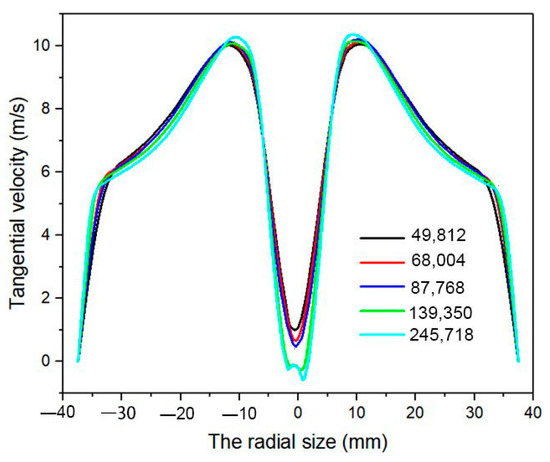
Figure 4.
Mesh independence verification.
3.3. Model Validation
It is necessary to first perform mathematical model validation using accurate test results prior to numerical simulations. For the verification of the accuracy of simulation results in this paper, simulation findings were analyzed and compared with the experimental values of Hsieh [32] and Delgadillo [33]. The distributions of tangential and axial velocities on conical and cylindrical section cross-sections are determined according to RSM and VOF models under similar boundary conditions to those applied by Hsieh. Figure 5a,b compares the simulation and Hsieh’s experimental results. Generally, the calculated distributions of tangential and axial velocities comply well with experimental data, and all numbers are lower than 5%. Validation of TFM model is performed according to Delgadillo’s experimental work, which applied feed solid concentration of 10.47% by weight. Figure 5c illustrates that there was a consistency between simulated and measured partition curves and that the two approaches’ overall trends are similar. Hence, it is concluded that the models employed in this research accurately predict hydrocyclone separation performance.

Figure 5.
Comparison between simulation data and experiment results: (a) tangential velocity; (b) axial velocity; (c) separation efficiency.
4. Results Analysis
The variation of structural parameters has resulted in inner flow field change, affecting particle motions. Hence, spiral structure effect on flow patterns should first be investigated.
4.1. Pressure Analysis
Hydrocyclones are a type of device that can convert pressure energy to kinetic energy, thereby generating centrifugal forces to separate different sizes of particles. Figure 6 shows the pressure distribution patterns on the ZY plane in different hydrocyclones. It can be observed that the pressure cloud chart becomes more symmetrical with the elevated position of the spiral structure, suggesting a more stable inner flow field. This conforms to the distribution rules that the pressure in the hydrocyclone decreases gradually with the decrease of the flowing radius.
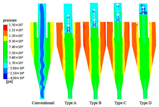
Figure 6.
Pressure distribution cloud charts on ZY plane.
In order to more clearly observe the variation characteristics of the inner pressure, as illustrated in Figure 7, distributions along diameter line on the planes of Z = 135 and 180 mm were adopted for further analyses. From Figure 7, it is found that pressure in conventional hydrocyclone was low; after the addition of the spiral structure, the inner pressure was increased. All the pressure values are positive, which means there was no air column in the cyclone. The reason is that the spiral structure of the overflow pipe prevents the entry of air through overflow pipe, and bottom flow back pressure achieves the effect of water sealing, so it is hard for air to enter. By analyzing the minimum pressure of the two sections, it was found that the pressure value increased by 8.372 × 10⁴ Pa and 6.761 × 10⁴ Pa respectively. The install position of the spiral structure in the overflow pipes is a key factor influencing pressure in hydrocyclone. The pressure in the Type B hydrocyclone was greatest, which can contribute to the preferred discharge of the concentrated particles on the wall surface, thereby reducing the probability of mixing coarse particles into inner rotational flow.
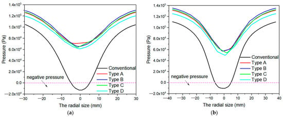
Figure 7.
Pressure curves at different sections: (a) z = 135 mm; (b) z = 180 mm.
4.2. Turbulence Intensity Analysis
Figure 8 illustrates turbulence intensity cloud charts on X = 0 plane in various hydrocyclones. From Figure 8, it can be found that after the addition of the spiral structure to the overflow pipe, the solid–liquid mixtures formed vortexes on the conical wall surface under dual backpressures of the overflow and underflow. At an appropriate turbulence intensity, the particles can be washed by turbulent flow, thereby contributing to the separation. The turbulent intensity of the spiral structure elements of the overflow was great, which is due to the arrangement and combination pattern of the spiral structure elements. This can help the refined particles with different sizes in the overflow intersect and mix with each other.
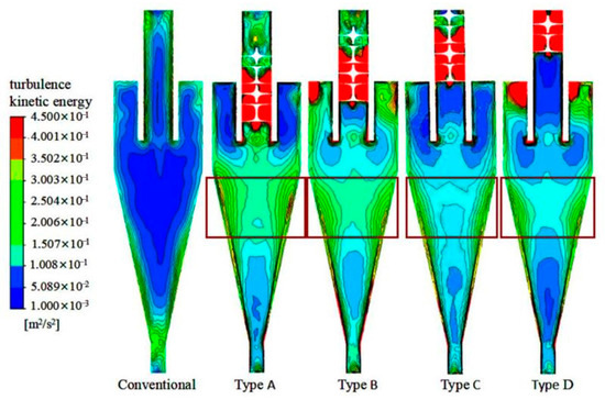
Figure 8.
Turbulence intensity analysis in the ZY plane.
Due to the existence of the turbulent kinetic energy, the retention time of liquid can be prolonged. This can be attributed to the energy exchange among vortexes as well as the exchange between the vortex and main flow, thereby improving the mixing performance in the radial direction. The existence of vortexes can contribute to better mixing. Turbulent kinetic energy was quite weak between Element 3 and Element 4, as shown in Figure 9, which relates to the arrangement of the adjacent elements at an intersection angle of 90° and the energy loss in the high-intensity turbulent flow caused by the change of the reverse direction.
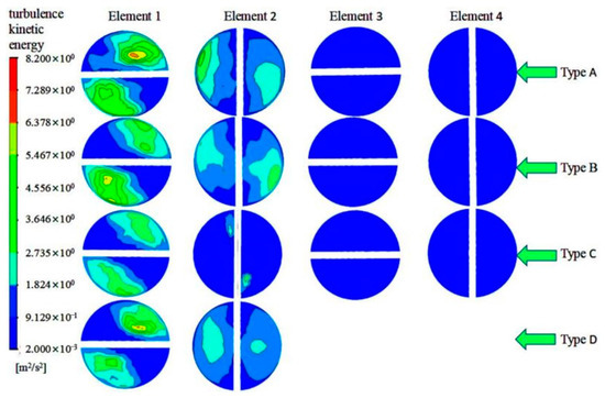
Figure 9.
Distribution patterns of the turbulent kinetic energy of four elements on spiral structure.
4.3. Analysis of Pressure Gradient
The pressure gradient was minimum at the wall surface. With the decline of the radius, the pressure gradient reached a maximum at the junction between forced vortex and free vortex, and then rapidly dropped. The distribution of the pressure gradient was similar to that of tangential velocity. Figure 10 illustrates pressure gradient cloud charts in different hydrocyclones. The addition of the spiral structure to the overflow pipe can significantly reduce the pressure gradient and lower the collision and extrusion of fine particles during movement; accordingly, more stable movement of fine particles towards the center can be observed, which can impose lower disturbance on flow field and thereby improve flow field stability.
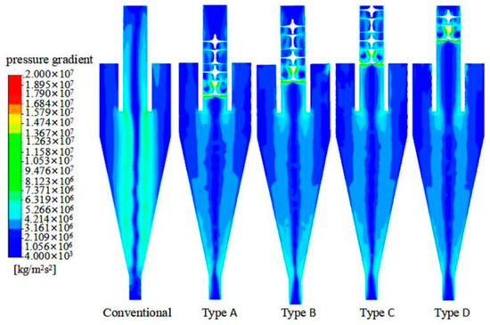
Figure 10.
Pressure gradient cloud charts.
Figure 11 shows pressure gradient variation curves on planes of z = 135 and z = 180 mm. As is seen in the Figure, the pressure drop in the hydrocyclones with spiral structures was lower than that in the conventional hydrocyclone. After the spiral structure was added, the pressure gradient in the two sections was reduced by 59.7% and 51.5%, respectively. It provides conditions for the rapid discharge of particles from the bottom flow.
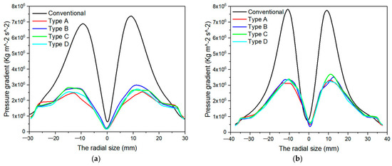
Figure 11.
Pressure gradient curves at different sections: (a) z = 135 mm; (b) z = 180 mm.
4.4. Analysis of Tangential Velocity
Tangential velocity is the main source of driving force and centrifugal force. Tangential velocity increased gradually from the surface of wall towards the center and dropped rapidly after approaching axle center. This M-shaped distribution pattern was consistent with combined vortex distribution characteristics. After adding the spiral structure to the overflow pipe, the tangential velocity was overall lower than that in a conventional hydrocyclone due to the resistance on the ascending fluid by the spiral structure, as shown in Figure 12.
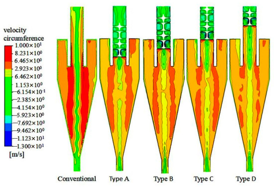
Figure 12.
The cloud charts of tangential velocity.
Figure 13 illustrates tangential velocity variation curves on planes of z = 135 mm and z = 180 mm. From the figure, it can be found that after the addition of the spiral structure to the overflow pipe, the tangential velocity was reduced. Therefore, fine particles entered into outer rotational flow only with difficulty, contributing to fine particle separation. With the increase of the spiral structure position, the tangential velocity firstly increases and then decreases. The tangential velocity of Type B is the largest, which is reduced by 1.846 m/s and 1.853 m/s, 21.2% and 20.6%, respectively, compared with the conventional cyclone. Under the premise of stable flow field, coarse particles migrate to the wall of hydrocyclone more easily, decreasing the entrance probability of coarse particles to the inner cyclone and effectively reducing overflow particle products.
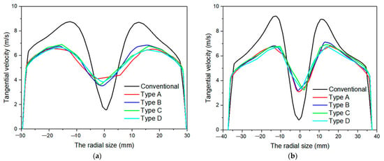
Figure 13.
Tangential velocity curves at various sections: (a) z = 135 mm; (b) z = 180 mm.
4.5. Analysis of Axial Velocity
The axial velocity determines the split ratio and the retention time. Figure 14 illustrates axial velocity cloud charts on ZY plane in various hydrocyclones. From Figure 14, the absolute value of the axial velocity along the positive direction was much greater than that along the negative direction at overflow pipe bottom, suggesting the discharge of a lot of media from the overflow. By connecting the points at the interface between the outer and the inner rotational flows with the axial velocity of 0, the zero envelopes can be plotted. After the addition of the spiral structure, the V-shaped zero envelopes observed in the conventional hydrocyclone turned to the W-shaped zero envelopes in the hydrocyclone with spiral structures. The main reason is described below. The backpressure generated in the flow field by the spiral elements in the overflow pipe and the additive backpressure at the underflow port imposed dual-extrusion on the inner flow field. The dual backpressures were not identical and formed a closed zero envelope at the lower position in the conical segment. By observing the interface where the overflow entered the spiral structure, it can be found that the axial velocity changed in direction and part of the fluid moved downward, which can be attributed to the hindrance of the spiral structure on the fluid. However, only a small part of the fluid changed axial velocity, imposing less of an effect on the overall energy mixing performance.
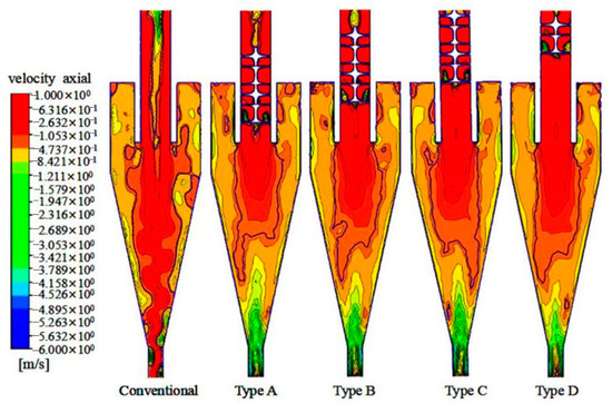
Figure 14.
Axial velocity cloud charts on ZY plane.
Figure 15 shows axial velocity variation curves on planes of z = 135 and z = 180 mm. After the addition of the spiral structure, the axial velocity was significantly reduced. A lower axial velocity can provide a longer time for the separation of media in the flow field, which can be conducive to the separation between coarse and fine particles and provide favorable conditions for the enhancement of separation accuracy. The axial velocity in the conventional hydrocyclone exhibits two direction changes on the z = 180 mm plane, suggesting circulating flow generation. Adding the spiral structure in overflow pipe can enhance flow field stability in a hydrocyclone and reduce the generation of circulating flow.
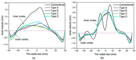
Figure 15.
Axial velocity curves at different sections: (a) z = 135 mm; (b) z = 180 mm.
Under the influence of the spiral structure, the centrifugal force generated during high-speed rotation formed a high-speed fluid region at the wall surface. The fluid can rotate around the hydraulic pressure center of the semicircular section. Under the action of residual energy of the rotational flow, the overflow products were subjected to the residual energy discharged from the overflow and entered the spiral structure for static mixing. Since various elements were alternately intersected at an angle of 90°, the flow field for the discharge of overflow imposed an interlaced mixing action, which can inevitably increase the upward resistance and bring about the corresponding energy loss. With the increasing number of spiral elements, the retention time of particles increased, accompanied with more favorable mixing performance in the hydrocyclone. Comparing the velocity distributions on the mid-sections of four sections as illustrated in Figure 16, velocity distribution in Type B hydrocyclone was more symmetrical. The cutting of the spiral stricture can hinder the velocity to a certain extent, and therefore the liquid cannot flow out rapidly, leading to a decrease of velocity when passing through the spiral elements.
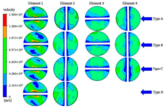
Figure 16.
Distribution patterns of the velocity of four elements on spiral structure.
4.6. Analysis of Separation Efficiency, Pressure Drop, and Split Ratio
The split ratio is considered as underflow volume flow rate to that at feed inlet. With a decrease of the split ratio, more fluid is discharged with overflow, reducing the secondary flow generated in the flow field and thereby having a lower dislocated particle number. Under cutting action by the spiral structure, coarse particles originally discharged from the underflow changed direction and returned to the cavity of the hydrocyclone for separation. The split ratio decreased gradually with the elevated position of the spiral structure in the overflow pipe, as shown in Figure 17. At a higher position of the spiral structure, lower backpressure was generated on the inner fluid. Under the same backpressure, the role of the backpressure of the underflow exceeded that of the overflow and gradually occupied a dominant role, and therefore more products were discharged with the overflow, leading to the decline in the split ratio.
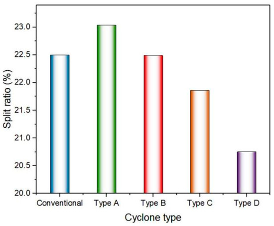
Figure 17.
The split ratio.
Decrease of pressure is the difference of static pressure between outlet and inlet. A small pressure drop within a certain range is favorable for the reduction of energy consumption and operation cost. The pressure drop in the Type B hydrocyclone was lowest, as illustrated in Figure 18, which can not only mix the rotational flows thoroughly but also reduce the energy consumption to a certain extent. Decrease of pressure in Type B hydrocyclone was obviously lower than the values of other hydrocyclones. A lower pressure drop is indicative of less energy consumption, which can promote energy conversion.
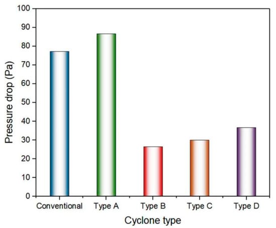
Figure 18.
Pressure drops.
Since total separation efficiency (ET) is strongly affected by the split ratio (SR), the reduced total separation efficiency (ET′) is shown in Figure 19, defined as ET′ = (ET − SR)/(1 − SR). As the install position of the spiral structure rose, cutting size first decreased and then increased. A minimum cutting size of 20.1 μm can be observed in the Type B hydrocyclone. By analyzing the separation efficiency of the underflow, the cutting size was reduced by 4.35 μm and 17.8%. The spiral structure can effectively reduce the size of overflow particles so that more particles can be discharged from the bottom flow.
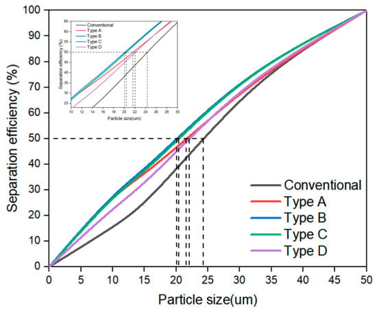
Figure 19.
Comparison of the particle separation efficiency of different hydrocyclones.
4.7. Analysis of Particle Cloud Chart
In the flow field, particles are subjected to a much greater acceleration of centrifugal force than the acceleration of gravity. Therefore, particles in the flow field are under a supergravity state. When the fluid medium entered the flow field from the feed inlet along the tangential direction, the particles with large density were subjected to greater centrifugal force under high-speed rotation than the low-density particles, which can lead to the appearance of velocity differences among different particles, thereby promoting the scattering of particles and the separation around different paths.
In order to directly investigate the particle distribution pattern, the cloud charts of particles with the sizes of 15 μm and 35 μm were plotted, as shown in Figure 20 and Figure 21. Through comparison, the concentration of a great number of particles can be observed at the wall surface of the conical section in the conventional hydrocyclone. This is due to the large axial velocity in the hydrocyclone and the too-low conical angle. The particles cannot be rapidly discharged. After the addition of the spiral structure, axial velocity was low and particle retention time was long, thereby providing sufficient time for the discharge of particles with the overflow and reducing the number of concentrated particles. It can also be observed from Figure 21 that almost no coarse particles with a size of 35 μm discharged with the overflow, thus coarse particles can be well separated and the refined products output from the overflow was good in quality.
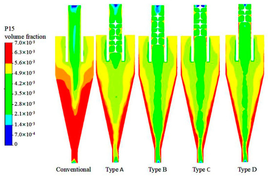
Figure 20.
Distribution pattern of particles 15 μm in size in different hydrocyclones.
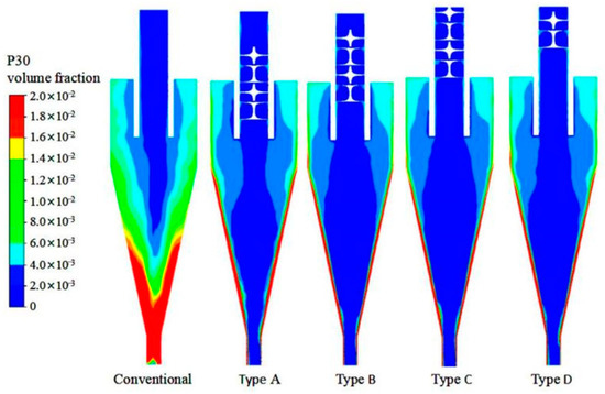
Figure 21.
Distribution pattern of particles 35 μm in size in different hydrocyclones.
5. Conclusions
In this study, we performed numerical simulation on the designed hydrocyclone after the addition of a spiral structure in the overflow pipe. Then, flow field characteristics, velocity field and pressure field on the section of the spiral element of the hydrocyclone were studied. The main conclusions drawn are as follows:
- A suitable spiral structure can reduce the pressure decrease of a hydrocyclone, and the Type B hydrocyclone has the smallest pressure drop with a 67.11% reduction compared to the conventional one.
- As the install position of the spiral structure rose, tangential velocity first increased and then reduced, and the tangential velocity was reduced by nearly 20% compared with the conventional hydrocyclone.
- As the install position of the spiral structure rose, cutting size first decreased and then increased, and minimum cutting size of 20.1 μm can be observed in the Type B hydrocyclone.
Author Contributions
P.L.: Conceptualization, writing—original draft preparation; W.F.: Methodology, software, formal analysis, writing—original draft preparation; L.J.: Conceptualization, funding acquisition, investigation, writing—review and editing; X.Y.: Software, data curation; Y.Z. (Yuekan Zhang): Validation, data curation; X.L.: Validation, data curation; Y.Z. (Yulong Zhang): Validation, data curation. All authors have read and agreed to the published version of the manuscript.
Funding
This work was supported by the National Natural Science Foundation of China (22108159) and the Natural Science Foundation of Shandong province, China (ZR2021QB068, ZR2020ME105).
Institutional Review Board Statement
Not applicable.
Informed Consent Statement
Not applicable.
Data Availability Statement
Not applicable.
Conflicts of Interest
The authors declare no conflict of interest.
References
- Atkinson, R.W.; Mills, I.C.; Walton, H.A.; Anderson, H.R. Fine particle components and health-a systematic review and meta-analysis of epidemiological time series studies of daily mortality and hospital admissions. J. Expo. Sci. Environ. Epidemiol. 2015, 25, 208–214. [Google Scholar] [CrossRef] [PubMed]
- Wang, J.D.; Wang, S.X.; Jiang, J.K.; Ding, A.J.; Zheng, M.; Zhao, B.; Wong, D.C.; Zhou, W.; Zheng, G.J.; Wang, L.; et al. Impact of aerosol-meteorology interactions on fine particle pollution during China’s severe haze episode in January 2013. Environ. Res. Lett. 2014, 9, 094002. [Google Scholar] [CrossRef]
- Thurston, G.D.; Burnett, R.T.; Turner, M.C.; Shi, Y.L.; Krewski, D.; Lall, R.; Ito, K.; Jerrett, M.; Gapstur, S.M.; Diver, W.R.; et al. Ischemic Heart Disease Mortality and Long-Term Exposure to Source-Related Components of U.S. Fine Particle Air Pollution. Environ. Health Perspect. 2016, 124, 785. [Google Scholar] [CrossRef] [PubMed]
- Zhou, S.P.; Bevis WL, M.; Leong, E.; Kan, H.S.; Ip, S.-K.; Liu, T.K. Optimized centre-feed clarifier design for the Tai Po Sewage Treatment Works, Hong Kong. Water Environ. J. 2010, 24, 140–146. [Google Scholar] [CrossRef]
- Alanya, S.; Yilmazel, Y.D.; Park, C.; Willis, J.L.; Keaney, J.; Kohl, P.M.; Hunt, J.A.; Duran, M. Anaerobic co-digestion of sewage sludge and primary clarifier skimmings for increased biogas production. Water Sci. Technol. J. Int. Assoc. Water Pollut. Res. 2013, 67, 174–179. [Google Scholar] [CrossRef]
- Lossing, H.; Champagne, P.; McLellan, P.J. Examination of sludge accumulation rates and sludge characteristics for a decentralized community wastewater treatment systems with individual primary clarifier tanks located in Wardsville (Ontario, Canada). Water Sci. Technol. 2010, 62, 2944–2952. [Google Scholar] [CrossRef] [PubMed]
- Kyriakidis, Y.N.; Silva, D.O.; Barrozo, M.A.S.; Vieira, L.G.M. Effect of variables related to the separation performance of a hydrocyclone with unprecedented geometric relationships. Powder Technol. 2018, 338, 645–653. [Google Scholar] [CrossRef]
- Mognon, J.L.; Silva, J.M.D.; Bicalho, I.C.; Ataide, C.H.; Duarte, C.R. Modular mini-hydrocyclone desilter type of 30 mm: An experimental and optimization study. Petrol. Sci. Eng. 2015, 129, 145–152. [Google Scholar] [CrossRef]
- Zhang, L.J.; Xia, X.H.; Zhang, J.F. Improving energy efficiency of cyclone circuits in coal beneficiation plants by pump-storage systems. Appl. Energy 2014, 119, 306–313. [Google Scholar] [CrossRef]
- Ghodrat, M.; Qi, Z.; Kuang, S.B.; Ji, L.; Yu, A.B. Computational investigation of the effect of particle density on the multiphase flows and performance of hydrocyclone. Miner. Eng. 2016, 90, 55–69. [Google Scholar] [CrossRef]
- Razmi, H.; Goharrizi, A.S.; Mohebbi, A. CFD simulation of an industrial hydrocyclone based on multiphase particle in cell (MPPIC) method. Sep. Purif. Technol. 2018, 209, 851–862. [Google Scholar] [CrossRef]
- Liu, L.; Zhao, L.X.; Sun, Y.; Gao, S.; Jiang, M.Z.; Jiang, M.H.; Rosso, D. Separation performance of hydrocyclones with medium rearrangement internals. J. Environ. Chem. Eng. 2021, 9, 105642. [Google Scholar] [CrossRef]
- Kumar, M.; Reddy, R.; Banerjee, R.; Mangadoddy, N. Effect of particle concentration on turbulent modulation inside hydrocyclone using coupled MPPIC-VOF method. Sep. Purif. Technol. 2021, 266, 118206. [Google Scholar] [CrossRef]
- Tian, J.Y.; Ni, L.; Song, T.; Zhao, J.N. CFD simulation of hydrocyclone-separation performance influenced by reflux device and different vortex-finder lengths. Sep. Purif. Technol. 2020, 233, 116013. [Google Scholar] [CrossRef]
- Lv, W.J.; Chen, J.Q.; Chang, Y.L.; Liu, H.L.; Wang, H.L. UU-type parallel mini-hydrocyclone group separation of fine particles from methanol-to-olefin industrial wastewater. Chem. Eng. Process.-Process Intensif. 2018, 131, 34–42. [Google Scholar] [CrossRef]
- Gayatree, P.; Priyam, D.; Chakraborty, S.; Meikap, B.C. Removal of fluoride from wastewater using HCl-treated activated alumina in a ribbed hydrocyclone separator. J. Environ. Sci. Health. Part A Toxic/Hazard. Subst. Environ. Eng. 2018, 53, 601–608. [Google Scholar] [CrossRef]
- Li, S.H.; Liu, Z.M.; Chang, Y.L.; Li, J.P.; Hu, J.K.; Shen, Q.S.; Wang, H.L. Removal of coke powders in coking wastewater using a hydrocyclone optimized by n-value. Sci. Total Environ. 2021, 752, 141887. [Google Scholar] [CrossRef] [PubMed]
- Yu, J.F.; Fu, J. Separation performance of an 8 mm mini-hydrocyclone and its application to the treatment of rice starch wastewater. Sep. Sci. Technol. 2020, 55, 313–320. [Google Scholar] [CrossRef]
- Youngseok, H.; Minsoo, M.; Seok, D. Development of a hybrid system for advanced wastewater treatment using high-rate settling and a flotation system with ballasted media. Int. Biodeterior. Biodegrad. 2016, 113, 256–261. [Google Scholar] [CrossRef]
- Gao, S.L.; Wei, D.Z.; Liu, W.G.; Ma, L.Q.; Lu, T.; Zhang, R.Y. CFD numerical simulation of flow velocity characteristics of hydrocyclone. Trans. Nonferrous Met. Soc. China 2011, 21, 2783–2789. [Google Scholar] [CrossRef]
- Hwang, K.J.; Hwang, Y.W.; Yoshida, H. Design of novel hydrocyclone for improving fine particle separation using computational fluid dynamics. Chem. Eng. Sci. 2011, 85, 62–68. [Google Scholar] [CrossRef]
- Padhi, M.; Mangadoddy, N.; Sreenivas, T.; Vakamalla, T.R.; Mainza, A.N. Study on multi-component particle behaviour in a hydrocyclone classifier using experimental and computational fluid dynamics techniques. Sep. Purif. Technol. 2019, 229, 115698. [Google Scholar] [CrossRef]
- Guo, D.; Jiang, X.Y.; Guo, M.Z.; Zeng, M.; Wu, N.; Hao, L.L.; Wang, C. Role of hydrocyclone separator on the formation and separation of aerobic granular sludge: Evaluating granulation efficiency and simulating hydrodynamic behavior. Sep. Purif. Technol. 2022, 283, 120231. [Google Scholar] [CrossRef]
- Zhao, Q.; Cui, B.Y.; Wei, D.Z.; Song, T.; Feng, Y.Q. Numerical analysis of the flow field and separation performance in hydrocyclones with different vortex finder wall thickness. Powder Technol. 2019, 345, 478–491. [Google Scholar] [CrossRef]
- Tripathy, S.K.; Bhoja, S.K.; Kumar, C.R.N. Suresh A short review on hydraulic classification and its development in mineral industry. Powder Technol. 2015, 270, 205–220. [Google Scholar] [CrossRef]
- Li, F.; Liu, P.K.; Yang, X.H.; Zhang, Y.K. Numerical simulation on the effects of different inlet pipe structures on the flow field and seperation performance in a hydrocyclone. Powder Technol. 2020, 373, 254–266. [Google Scholar] [CrossRef]
- Yang, X.H.; Simmons, M.J.H.; Liu, P.K.; Zhang, Y.K.; Jiang, L.Y. Effect of feed body geometry on separation performance of hydrocyclone. Sep. Sci. Technol. 2019, 54, 2959–2970. [Google Scholar] [CrossRef]
- Raviraju, V.; Kumar, P.A.; Sivakumar, S. Computational investigation of a novel hydrocyclone for fines bypass reduction. Powder Technol. 2022, 395, 501–515. [Google Scholar] [CrossRef]
- Hou, D.X.; Cui, B.Y.; Zhao, Q. Research on the structure of the cylindrical hydrocyclone spigot to mitigate the misplacement of particles. Powder Technol. 2021, 387, 61–71. [Google Scholar] [CrossRef]
- Vega-Garciaa, D.; Cilliersb, J.J.; Brito-Parada, P.R. CFD modelling of particle classification in mini-hydrocyclones. Sep. Purif. Technol. 2020, 251, 117253. [Google Scholar] [CrossRef]
- Hou, D.X.; Cui, B.Y.; Zhang, H.; Zhao, Q.; Ji, A.K.; Wei, D.Z.; Feng, Y.Q. Designing the hydrocyclone with flat bottom structure for weakening bypass effect. Powder Technol. 2021, 394, 724–734. [Google Scholar] [CrossRef]
- Hsieh, K.T. Phenomenological Model of the Hydrocyclone; The University of Utah: Salt Lake City, UT, USA, 1988. [Google Scholar]
- Delgadillo, J. Modeling of 75 and 250 mm Hydrocyclones and Exploration of Novel Design Using Computation Fluid Dhnamics. Ph.D. Thesis, The University of Utah, Salt Lake City, UT, USA, 2006. [Google Scholar]
Disclaimer/Publisher’s Note: The statements, opinions and data contained in all publications are solely those of the individual author(s) and contributor(s) and not of MDPI and/or the editor(s). MDPI and/or the editor(s) disclaim responsibility for any injury to people or property resulting from any ideas, methods, instructions or products referred to in the content. |
© 2023 by the authors. Licensee MDPI, Basel, Switzerland. This article is an open access article distributed under the terms and conditions of the Creative Commons Attribution (CC BY) license (https://creativecommons.org/licenses/by/4.0/).