Article

Application of Cylindrical Fin to Improve Heat Transfer Rate in Micro Heat Exchangers Containing Nanofluid under Magnetic Field

1
Mechanical Engineering Department, Faculty of Engineering, King Abdulaziz University, Jeddah 80204, Saudi Arabia
2
Center Excellence of Renewable Energy and Power, King Abdulaziz University, Jeddah 80204, Saudi Arabia
3
Department of Electrical Engineering, College of Engineering, Taif University, Taif 21944, Saudi Arabia
4
Architectural Engineering Department, Faculty of Engineering, Taif University, Taif 21944, Saudi Arabia
5
Department of Mechanical and Aeronautical Engineering, University of Pretoria, Pretoria 0028, South Africa
6
Department of Medical Research, China Medical University Hospital, China Medical University, Taichung 404, Taiwan
7
Independent Researcher, 38106 Braunschweig, Germany
*
Authors to whom correspondence should be addressed.
Processes 2021, 9(8), 1278; https://doi.org/10.3390/pr9081278
Submission received: 12 July 2021 / Revised: 20 July 2021 / Accepted: 22 July 2021 / Published: 24 July 2021
(This article belongs to the Section Materials Processes)

Abstract

:
In this study, the convective mode heat transfer phenomena of bi-phase elasticoviscous (non-Newtonian) nanofluid is quantified by forcefully flowing it through a specially designed microchannel test section. The test section, which is rectangularly cross-sectioned and annexed internally with cylindrical needle ribs is numerically investigated by considering the walls to be maintained at a constant temperature, and to be susceptible to a magnetizing force field. The governing system-state equations are numerically deciphered using control volume procedure and SIMPLEC algorithm. With the Reynolds number (Re) varying in the turbulent range from 3000 to 11,000, the system-state equations are solved using the Eulerian–Eulerian monofluid Two-Phase Model (TPM). For the purpose of achieving an apt geometry based on the best thermo-hydraulic behavior, an optimization study must be mandatory. The geometry of the cylindrical rib consists of h (10 × 10−3, 15 × 10−3, 20 × 10−3), p (1.0, 1.5), and d (8 × 10⁻³, 10 × 10−3, 12 × 10−3), which, respectively, defines the height, pitch, and diameter of the obstacles, with the dimensions placed within the braces being quantified in mm. The results demonstrated that the magnetic field leads to an enhanced amount of average Nusselt number (Nuav) in contrast with the occurrence at B = 0.0. This is due to the that the magnetic field pushes nanoparticles towards the bottom wall. It was found that B = 0.5 T has the maximum heat transfer compared with the other magnetic fields. The channel with h = 15 μm height leads to the maximum value of Nuav at all studied R e for constant values of d and h. The channel with p = 1.5 μm results in the maximum value of Nuav at all studied R e for constant values of d and h. The microchannel with d = 8 μm, p = 1.5 μm, and h = 15 μm in the presence of the magnetic field with B = 0.5 T is the best geometry in the present work.

1. Introduction

The limelight on energy conserving Non-Newtonian fluidation and sustainability has been drawing widespread attention to the modified heat transfer and flow behavior through different techniques to accomplish superior thermal performance. To accomplish further effectual mechanism in calorific equipment, numerous endeavors have been proposed by researchers. One of the methods by which the effectiveness of the equipment is ameliorated is by accustoming the grooves and/or ribs. This technique causes a better mixing of fluid, destroying the viscous sub-layer and creating confined swirls. Th generation of confined swirls results in thermal resistance abatement and, hence, intensifies the heat transfer [1,2,3,4,5,6]. Another technique to enhance the thermal efficiency of thermal devices is to use nanofluids that have higher thermal conductivity than common fluids [7,8,9,10,11,12]. Nanofluids are amalgamated fluid dispersions of metallic/non-metallic dense powders or particulates in common base liquids [13,14,15,16,17].
Because of the importance of wavy-wall channels in thermic apparatus like heat exchangers, studies revolving around them have been conducted by experimenters. In this regard, Oyakawa et al. [18] executed a mathematical assessment for the sake of evaluating the impact of duct width on thermal process augmentation in a sinusoidal duct. Convective thermal performance within a periodic wavy channel was analyzed numerically by Wang and Vanka [19], who found that there was a 2.5 fold augmentation in heat transfer of the transitional-flow regime. Rush et al. [20] worked out an experiential study on hydrothermal aspects of fluid flow in sinusoidal passages. It was revealed that the Reynolds number ( R e ) and channel configuration have a crucial effect on the zonal Nusselt number. Ničeno and Nobile [21] numerically evaluated forced convection thermal exchange phenomena through a wavy channel under a turbulent flow regime. They observed a substantial improvement in thermic-convection when the flow regime is changed. Numerical investigation on the viscous flow prone fluid under forced convection by Wang and Chen [22] resulted in an attenuated performance due to an escalated Reynolds number and wavelength amplitude ratio. A similar analysis by Yin et al. [23], with airflow through a sinusoidal channel under variable wavelengths, depicted an optimized hydrothermal performance complying with minimum R e and zero phase shifts. Likewise, Ahmed et al. [24] used a sinusoidally oriented channel with different wavelengths, indicating that the convective behavior hikes with R e , wavy-wall amplitude, besides volume concentration of nanoparticles.
The forced convective turbulent movement of SiO2-water nanofluid across various corrugated channels was investigated by Ajeel et al. [25], between 10,000 and 30,000 Reynolds number ranges, numerically and experimentally. The new style of trapezoidal-corrugated channel led them to reach the heat transfer augmentation for silica nanofluid compared with the base fluid. Additionally, its pressure drop was increased reasonably.
Rajabi et al. [26] simulated a turbulent nanofluid flow through a specially designed narrow channel. The channel contained a spherical dimple on it, with the entire channel walls being heated. Their study illustrated that the local heat transfer coefficient in bi-phased blend was enhanced up to 2% by a 2% boosting nanoparticles’ volume fraction, which had no variety in different depths. Moreover, changing the pressure coefficient of the water-Alumina nanofluid was the same as the water-Cu nanofluid. In addition, the vortex strength and pressure distribution were not affected by the volume fraction of nanoparticles.
During a numerical assessment, besides thermal attributes, hydraulic attributes of nanofluid flowing through a trapezoidal-corrugated channel under a turbulent zone were studied by Ajeel et al. [27]. The study focused on four varieties of fluid dispersion samples by utilizing the finite volume method solution for governing equations. They specifically examined various settings, including the adiabatic condition for the channels that were considered to be straight, trapezoidal (two configurations), and have zigzag symmetry besides encompassing isoheat flux for the walls that were corrugated profiled. The amassed heat transfer enhancement was the result of employing SiO2-water through the trapezoidal-corrugated symmetric profile channel.
Khoshvaght-Aliabadia and Salami [28] conducted a numerical analysis to evaluate the swirl flow convection effect of a water-based nanofluid forcefully flown through an offset stripped conduit. They extended their investigation by changing different parameters such as the channel length, channel height, strip length, strip pitch, strip thickness, Reynolds number, and nanoparticles’ concentration up to 4%. The outcome resulted in an attenuated thermo-hydraulic attribute due to the height of the channel.
A numerical simulation on the turbulent flow was performed by Parsaiemehr et al. [29] in which a rectangular channel, containing water/Al2O3 nanofluid, was consumed to evaluate the essence of the attack angle of ribs (0 to 180°), percentage particle volume proportion (0–4), and Reynolds number (15,000 to 30,000) on to heat transfer. The uttermost rate of heat transfer surge was achieved analogous to 60° attack angle. Furthermore, by implementing nanofluids and ribs in high Reynolds numbers PEC amplified as well.
Ahmed et al. [30] conducted a numerical study about turbulent forced convection by utilizing four different nanofluids with changing diameter of nanoparticles and solid volume fraction through a triangular-corrugated conduit under a specific range of Reynolds number. The outcome was so significant that with diminishing particle dimensions up to 70 nm, the boosting volume fraction impacted certain parameters such as fall in fluid pressure and augmented thermo-convective performance, evident from the rise in the average Nusselt number.
It should be noted that various ribs and corrugations were adopted in the majority of the aforementioned numerical experiments to evaluate their influences on thermo-convective phenomena within a microchannel filled with colloidal dispersions. However, pertaining to the existing literature works [24,31,32,33,34,35,36,37,38,39,40,41,42,43,44,45,46,47,48], it can be ascertained that the influence of corrugated-wall microchannels on the thermal-hydraulic behaviour of the thermo-convective mechanisms of an elasticoviscous fluid in a microchannel that is susceptible to magnetic flux density has not been reported.
The goal of the present article focuses on the finite volume method based on numerical analysis of the thermo-hydraulic attribute of an elastoviscous fluid flowing through a microchannel of varied corrugation geometries that is vulnerable to magnetic flux density. For this purpose, six different fins structure were studied. The effects of magnetic fields was investigated in all cases. The results are presented for mean Nusselt number, pressure drop, friction coefficient, and PEC.

2. Mathematical Model Representation

2.1. Physical Model, Governing Equations, and Boundary Constraints

Figure 1 displays the represented sketch of the microchannel and the limiting constraints at the boundary. The geometry consisted of three sections, namely, an inlet, a corrugated bottom wall test section, and an exit section. The height and width of all three sections were H = 40 μm and W = 70 μm, respectively. The inlet and outlet sections were, respectively, used to affirm a fully developed flow within the corrugated test section and evade the detrimental pressure effects on the hydrothermal performance of nanofluid flow. The length of each section was 4 mm. Table 1 reports different cases of geometrical parameters considered in the present study.
For the present analysis, the geometry of the cylindrical rib consisted of h (10 × 10−3, 15 × 10−3, 20 × 10−3), p (1.0, 1.5), and d (8 × 10⁻³, 10 × 10−3, 12 × 10−3), which, respectively, defined the height, pitch, and diameter of the obstacles, with the dimensions placed within the braces being quantified in mm. The velocity bounding constraints at the inlet in proportion to the Re range from 3000 to 11,000 defined the leading end of the minichannel, whereas the pressure bounding constraints at the outlet exposed the trailing exit end. The walls of the corrugated side were prone to isothermal scenario with Tw = 400 K, and the system was exposed to environmental condition of 300 K as Tin < Tw. Besides, it was presumed that the fluid circulation and thermic-convection exchange within the minichannel were steady-state. Additionally, three different magnetic fields ( B = 0, 0.2, and 0.5 T) were implemented at the test section base wall. Dispersion of Al2O3 nanoparticles in a mixture of water and carboxyl methyl cellulose (H2O 99.5%:0.5% CMC) as a colloidal suspension was considered as the thermic fluid, which is an elasticoviscous fluid. In the present simulations, φ was between 0–1.5%, and the particle dimensions were between 25 and 100 nm. The thermophysical properties of all the constituents and fluid samples are presented in Table 2.
The system-state equations are listed in Table 3 below [31,39]:
where H is the magnetic field strength and B is the magnetic flux density.
The R e number
Re = ρ n f V m D h μ n f
The average Nusselt number (Nuav)
Nu av = hD h k nf
The pressure drop
Δ p = p av , inlet p av , outlet
The average friction factor
f = 2 ( L D h ) ( Δ P ρ n f V m 2 )
The thermal-hydraulic performance evaluation criteria (PEC)
PEC = ( Nu av Nu av , s ) · ( f f s ) 1 / 3
Density and heat capacity
ρ n f = ( 1 ϕ ) ρ b f + ϕ ρ n p
c P , n f = ( 1 ϕ ) ( ρ c P ) b f + ϕ ( ρ c P ) n p ρ n f
Thermal conductivity
k nf k f = 1 + 4.4 Re np 0.4   Pr 0.66 ( T T fr ) 10 ( k np k bf ) 0.03   φ 0.66
Re n p is
Re n p = ρ b f u B d n p μ b f
where kb = 138.066 × 10⁻²⁵ J/K.
Dynamic viscosity
μ nf μ f = ( 1 34.87 ( d np d f ) 0.3   φ 1.03 ) 1
where d f is non-Newtonian base fluid molecule.
Thermal diffusivity
α n f = k n f ( ρ c P ) n f
To perform the numerical analysis and acquire a solution, the finite volume method was adopted. Besides, the SIMPLEC algorithm was availed to solve the speed and pressure coupling conditions. The maximum error in calculating different parameters was 10−6. With the intention of simulating the flow under turbulent regime, the standard k-ε model was exercised. The Eulerian–Eulerian monofluid Two-Phase Model (TPM) was put to use for modeling bi-phase flow [49,50,51,52,53,54,55,56,57,58,59,60].

2.2. Validation

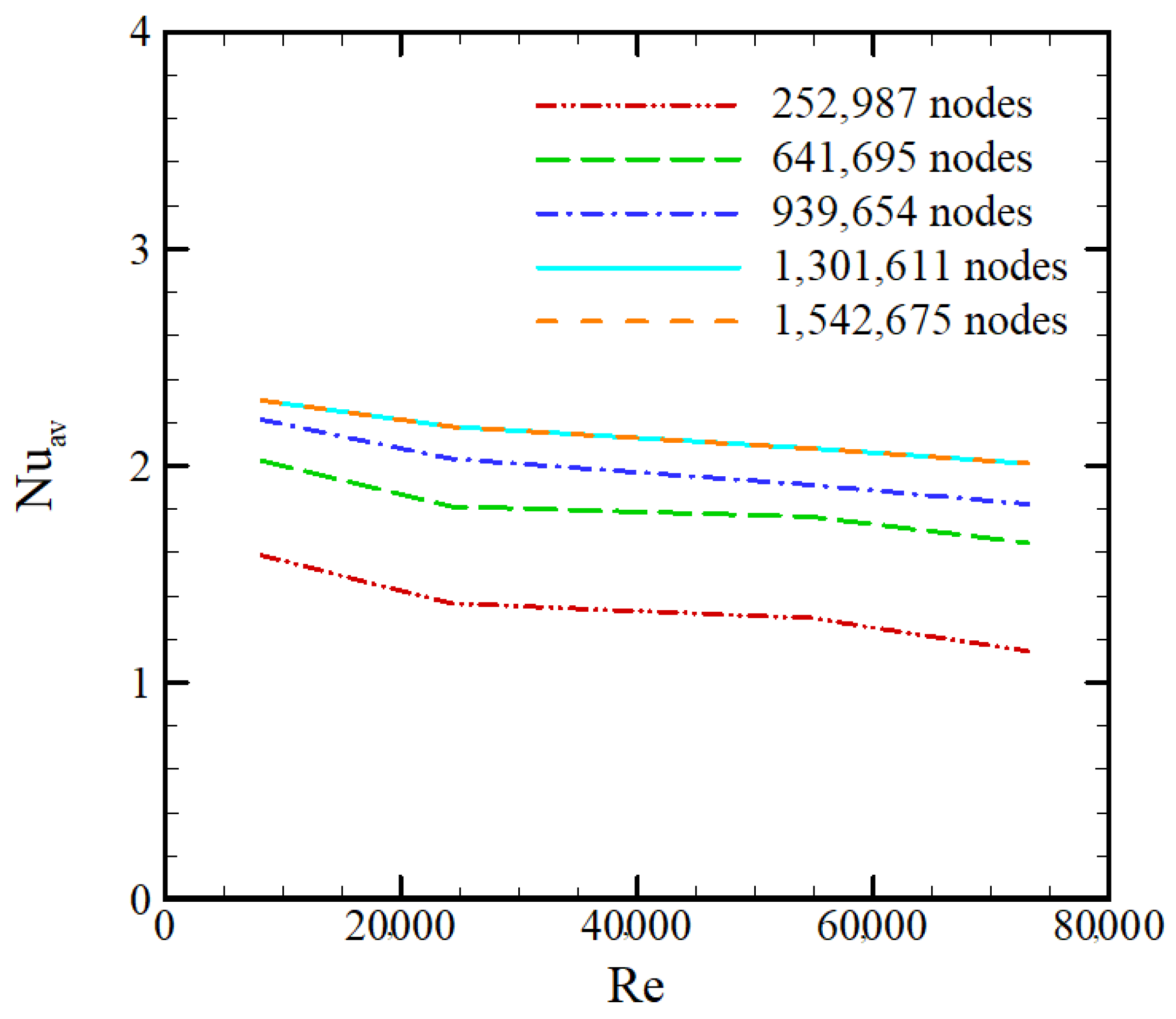
The grid independency test was performed using five different grid resolutions of 252,987, 641,695, 939,654, 1,301,611, and 1,542,675 for the 3D microchannel with corrugations. Nuav values calculated on the lower wall were compared for different grids, and it was found that the grid resolution of 1,301,611 could be selected to achieve accurate results with reasonable computational time (Figure 2). CFD software code presented for this study was validated by quantifying the Nuav of water flow along a microchannel and analyzing the same with existing results of Akbari et al. [35]. They investigated the influence of particle dimension and velocity over the thermo-convective behaviour in elasticoviscous nanofluid flow. Their experimentation dealt with analyzing the thermo-convective behavior and hydrodynamic attributes pertaining to the flow characteristics of non-Newtonian nanodispersion. They numerically simulated laminar forced convection of elasticoviscous nanodispersion flow comprising of water-carboxy methyl cellulose and alumina at varied particle concentrations (0.5 and 1.5). According to Figure 3, the results of our study are on par with those of Akbari et al. [35].

3. Results and Discussion

In this segment, the influence of unconnected parameters, in particular, corrugation height, pitch, and diameter, on elasticoviscous nanofluid flow and heat transfer with or without applying magnetic field is presented and analyzed extensively.
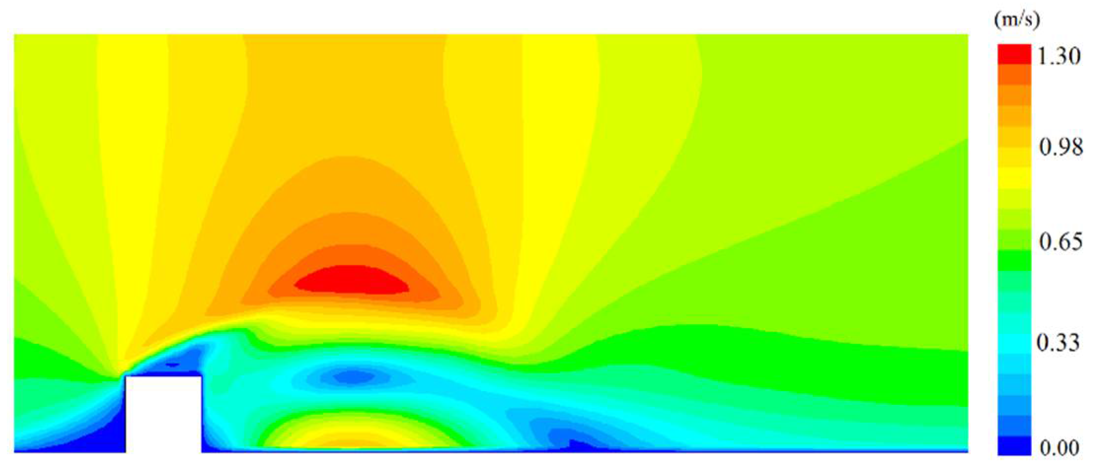
Figure 4 and Figure 5 represents the temperature profiles in the last rib across the midplane zone of the channel when prone to B = 0.2 T and 0.5 T, respectively. As can be seen in these figures, each corrugation influenced the adjacent fluid flow. The temperature of fluid film near the wall augmented when the magnetic field strength increased. Similarly, Figure 6 and Figure 7 illustrates the velocity profile in the last rib across the midplane zone of channel when susceptible to B = 0.2 T and 0.5 T, respectively. As can be seen in these figures, some weak and strong waves are shown near to the rib, which impacted the fluid flow. Therefore, it is evident that the influence of the ribs on the fluid flow near the wall increased when the magnetic field strength incremented.
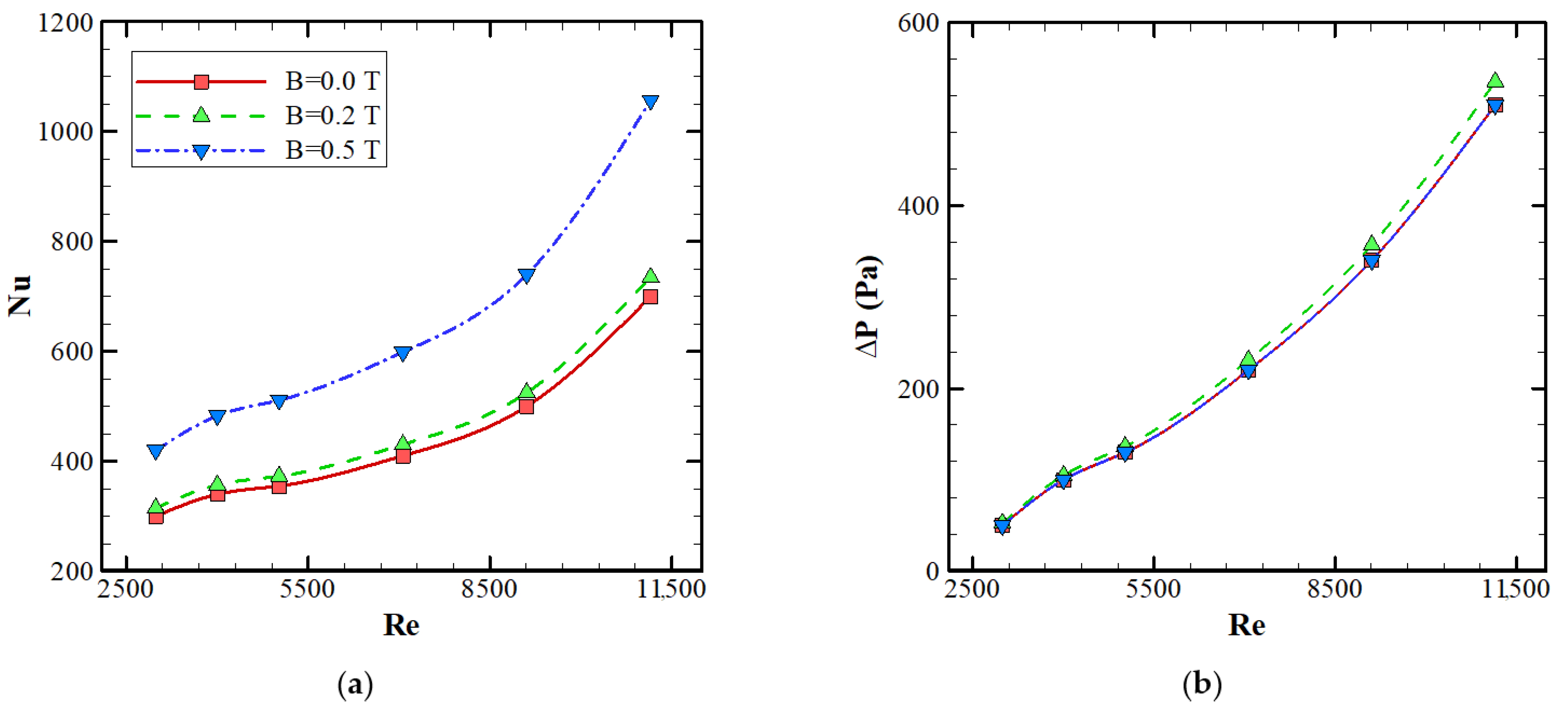
The impact of magnetic flux density (magnetic field effect) over the Nuav, pressure drop, friction factor, and PEC for h = 10 μm, p = 1.0 μm, d = 8 μm and different Re is elucidated in Figure 8. As shown in Figure 8a, the Nuav increased with R e . Under every studied scenario, higher estimates of Nuav were achieved in the microchannel prone to the effect of the magnetic flux density than in the conventional microchannel (B = 0.0). This is due to the fact that the magnetic field pushed the nanoparticles proximate to the base wall, influencing higher disturbances and decreasing the boundary layer thickness on the base wall, resulting in higher temperature gradients. It can be observed that B = 0.5 T had the maximum heat transfer compared with the other values. This pertains to the fact that the stronger the magnetic field, the turbulence intensity increases, leading to a higher mixing rate of the elasticoviscous nanofluid at higher R e values. In addition, it can be seen that the magnetic field with B = 0.1 T did not have a substantial impact on the thermal behaviour across the flow conduit.
According to Figure 8b, it was revealed that the microchannel generated a high pressure drop due to the ribs disturbing the nano-Newtonian flow, leading to a high pressure drop penalty. In other words, corrugated channels led to a high turbulent flow and, subsequently, a high pressure drop. In this figure, the presence of the magnetic field did not have a significant influence on loss in pressure. Figure 8c demonstrates the fluctuation of friction factor versus R e for various magnetic fields. It was realized that the magnetic field did not have a significant influence on the friction factor of the microchannel. Figure 8d demonstrates the influence of the magnetic field on PEC versus R e . It is concluded that the magnetic field with B = 0.5 T had the highest PEC in all ranges of R e . The maximum value of PEC was 1.561 at Re = 11,000. Therefore, it is observed that the magnetic field with B = 0.5 T leads to maximum enhancement of thermo-convective behaviour. In accordance with the present results, the most efficient geometry case was the microchannel filled with elasticoviscous nanofluid prone to B = 0.5 T magnetic flux density. Thus, this magnetic field was selected for further simulations.
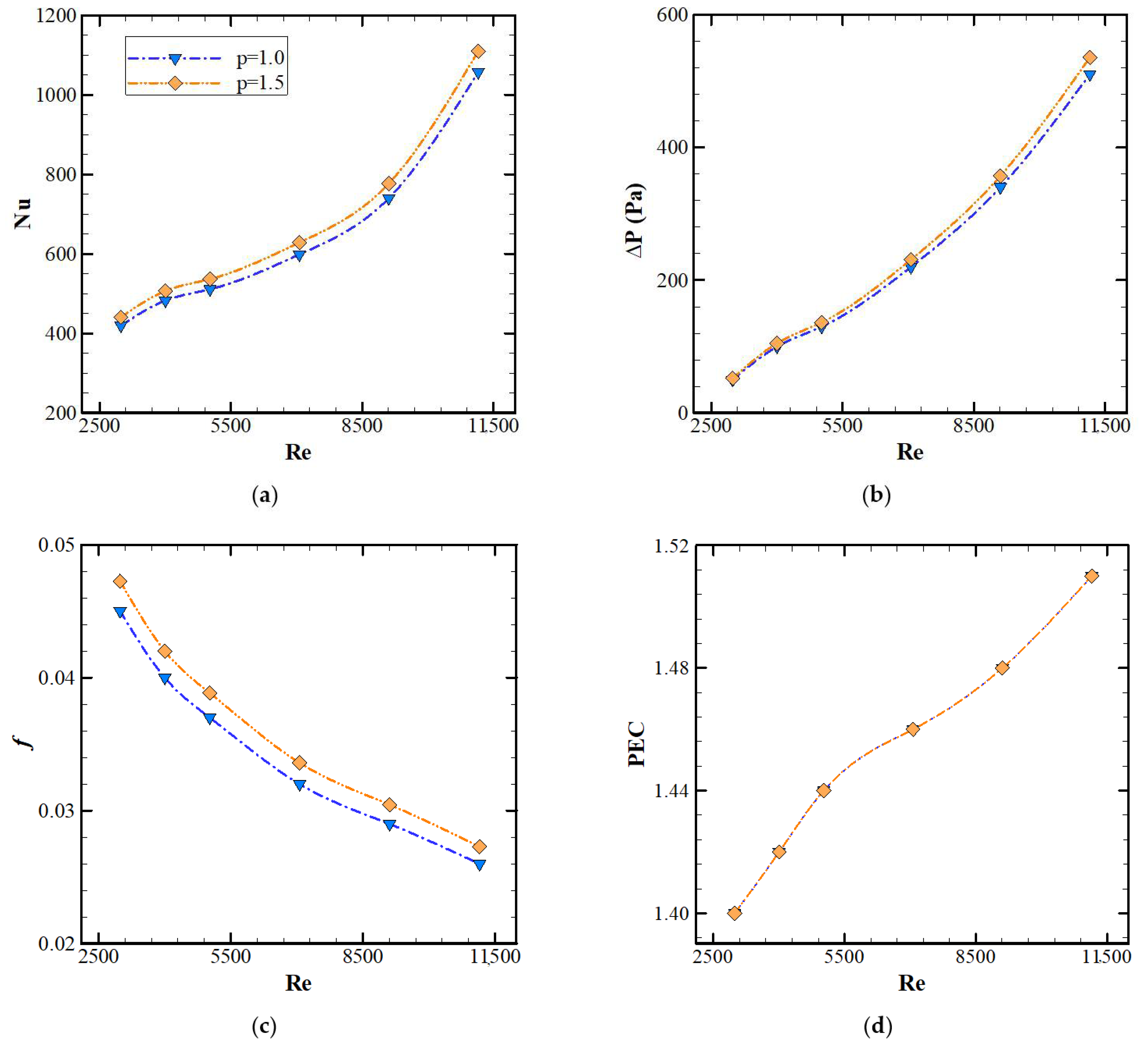
Figure 9 depicts the impact of corrugation pitch on Nuav, reduction in pressure, friction factor, and PEC for h = 10 μm and d = 8 μm in the vicinity of B = 0.5 T magnetic flux density and different R e . The Nuav versus inlet flow velocity (or R e ) is shown in Figure 9a for different corrugation pitches. It is worth noting that the rise in inlet velocity or R e , augmented the Nuav. Higher R e corresponded to higher fluid velocity and led to larger disturbances in the flow and, hence, an improvement in the heat transfer rate. In addition, the channel with p = 1.5 μm had the maximum value of Nuav for all studied inlet velocities. Additionally, the pressure drop is presented in Figure 9b for different pitches of microchannel and the studied range of R e . It was observed that p = 1.5 μm had the maximum value of pressure drop among all considered pitches. Therefore, the reduction in pressure widened when the Re intensified. Figure 9c demonstrates the fluctuation in friction factor along the microchannel with reference to R e . Analogous to p = 1.5 μm, the measure of friction factor seems to be the highest when matched with other geometries. In contrast, the minimum estimate is associated with p = 1.0 μm. It is clear that the friction factor reduced slightly for all geometries. Figure 9d shows the PECs evaluated using different values of Nuav and friction factor coefficients. The results demonstrated that the thermal-hydraulic PEC values related to each studied case had a fairly similar trend for the discussed span of inlet velocity. This explains that the PECs for the microchannel enhanced with the inlet velocity, resulting in an optimal R e corresponding to the maximum thermal-hydraulic PEC index for each configuration. The optimal R e was 11,000 for all examined design cases. The thermal-hydraulic PEC of microchannel with p = 1.0 and p = 1.5 μm were the same. However, the value of PEC for the microchannel with the pitch of p = 1.5 μm at Re = 11,000 was 1.569, despite the fact that this estimate for the model with p = 1.0 μm at Re = 11,000 was 1.561. Therefore, corrugation pitch of p = 1.5 μm was selected for further simulations.
Figure 10 exhibits the effect of corrugation height upon Nuav, loss in pressure, friction factor coefficient, and thermal-hydraulic PEC for the microchannel with p = 1.5 μm and d = 8 μm in the presence of magnetic field B = 0.5 T and different Re. The Nuav versus R e is shown in Figure 10a for different corrugation heights. It can be observed that as the R e increased, the Nuav increased. Besides, the channel with h = 15 μm had the maximum value of Nuav at all studied velocities. The pressure drop is presented in Figure 10b for different pitches of microchannel and different values of R e . It is observed that h = 20 μm led to a maximum value of pressure drop among all considered heights. Therefore, the loss in pressure widened when there was intensification of R e . Figure 10c demonstrates the friction factor fluctuation throughout the microchannel for the discussed zone of R e . The estimate of friction factor coefficient for h = 20 μm was the highest, in contrast to other studied geometries, meanwhile, at h = 10 μm, the minimum value was eminent. Thus, the friction factor coefficient diminished slightly with the flow velocities for all studied geometries.
Figure 10d shows the thermal and hydraulic PECs evaluated using obtained Nuav values and friction factor coefficient. The findings imply that the quantum of thermal and hydraulic PEC had fairly analogous tendencies for all cases at different Re. It was found that the thermal and hydraulic PECs increased with the flow velocity, then there was an ideal flow velocity in proportion to the maximum thermal and hydraulic PEC index for each design case. The best possible R e was related to Re = 11,000 for all examined design cases. The thermal and hydraulic PEC of the microchannel with h = 15 μm had the maximum value among all cases. The value of thermal and hydraulic PEC for the microchannel with pitch of h = 15 μm at Re = 11,000 was 1.582, while it was 1.569 akin to h = 10 μm at the same Re. Therefore, a corrugation height of h = 15 μm was selected for further simulations.
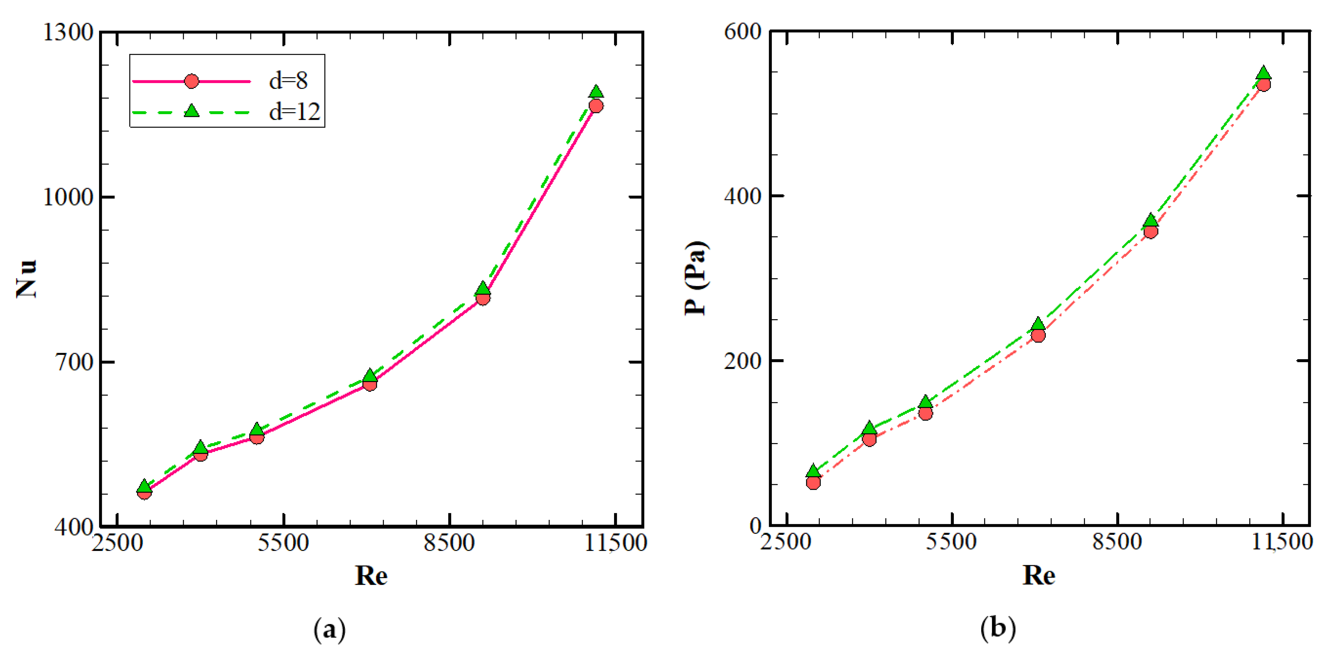
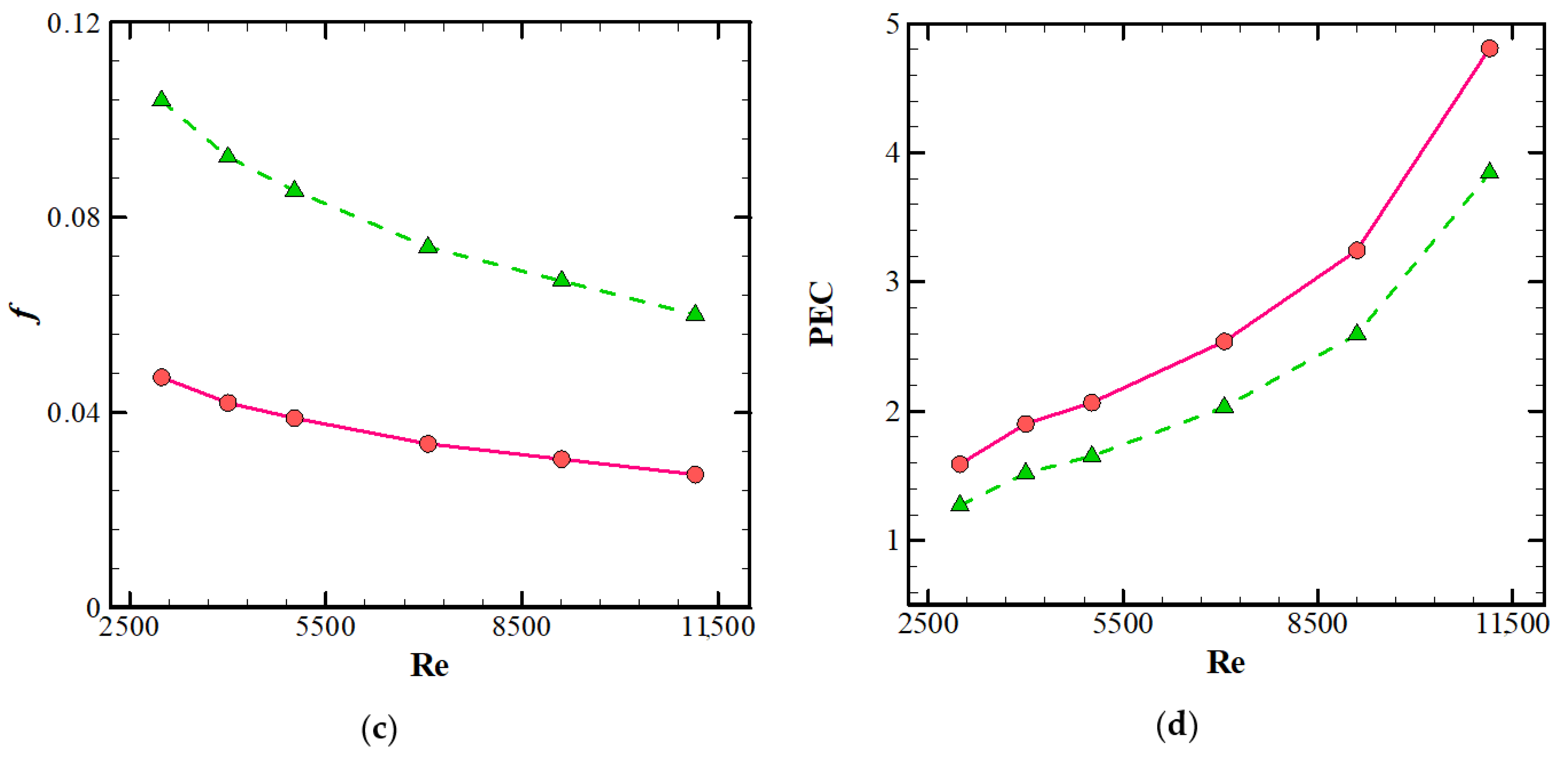
Figure 11 exhibits the impact of various corrugations on Nuav, pressure reduction penalty, friction factor coefficient, and thermal and hydraulic PEC index for the microchannel with p = 1.5 μm and d = 8 μm in the vicinity of B = 0.5 T magnetic field and different Re. The evaluated Nuav distribution versus different flow velocities is shown in Figure 11a for different corrugation diameters. It can be observed that as the R e increased, the Nuav increased. Higher R e corresponded to higher fluid velocity, leading to larger disturbances in the flow and hence an improvement in the heat transfer rate. It was also realized that the channel with the diameter of d = 12 μm had the maximum value of Nuav for all studied flow velocities. The pressure drop is presented in Figure 11b for different pitches of microchannel and different Re. It was observed that d = 12 μm had the maximum value of pressure drop among all considered pitches. Therefore, the pressure drop increased with the Re.
Figure 11c demonstrates the friction factor coefficient along the microchannel for different values of R e . The value of friction factor coefficient for d = 12 μm was the maximal as opposed to other geometries. In contrast, the minimum measure pertained to d = 8 μm. Moreover, it is noteworthy that the friction factor coefficient declined slightly with the flow velocity for all geometries. Figure 11d shows the PECs evaluated using Nuav and friction factor coefficient. The outcomes depict that the quantum of thermal and hydraulic PEC index had fairly analogous tendencies in the measured zone of flow velocity for all cases. The ideal flow velocity was related to Re = 11,000 for all examined cases. The thermal and hydraulic PEC index of microchannel with d = 12 μm had the maximum value for all flow velocities. The value of the thermal and hydraulic PEC index for microchannel with the diameter of d = 8 μm at Re = 11,000 was 1.588, whereas it was 1.582 pertaining to d = 12 μm at the same Re.
Therefore, the ideal geometry as per the study was the microchannel with d = 8 μm, p = 1.5 μm, and h = 15 μm susceptible to B = 0.5 T magnetic field.

4. Limitations

The need for computers with a powerful CPU and high RAM was one of the requirements for this study using numerical simulation. High computational costs are one of the issues that should be considered in performing numerical simulations. Considering the impossibility of performing experiments, it is not possible to compare numerical results with appropriate laboratory results in this field.

5. Conclusions

The prime purpose of the present numerical study is to assess the influence of diversified corrugation configurations on the hydrothermal performance of an elasticoviscous nanofluid flowing inside a microchannel prone to a magnetic field. The governing system-state equations can be numerically deciphered using control volume procedure and SIMPLEC algorithm. With the Re varying in the turbulent range from 3000 to 11,000, the system-state equations can be solved using the Eulerian–Eulerian monofluid Two-Phase Model (TPM). According to the obtained findings:
  • The presence of a magnetic field leads to higher values of Nuav.
  • The magnetic field with B = 0.5 T leads to the maximum heat transfer compared to the other fields.
  • Usage of a magnetic field with B = 0.1 T did not have a substantial impact on the thermal performance of a channel.
  • The channel with h = 15 μm height leads to the maximum value of Nuav at all studied R e for constant values of d and h.
  • The channel with p = 1.5 μm results in the maximum value of Nuav at all studied R e for constant values of d and h.
  • The channel with d = 8 μm leads to the maximum value of Nuav at all studied R e for constant values of d and h.

Author Contributions

Conceptualization, Y.K.; Data curation, Y.K. and A.A. (Ahmad Alahmadi); Formal analysis, Y.K., S.J.K. and A.A. (Ahmad Alahmadi); Investigation, Y.K., A.A. (Ahmad Alahmadi), S.J.K., and A.A. (Ali Alzaed); Methodology, Y.K., A.A. (Ahmad Alahmadi) and A.A. (Ali Alzaed); Supervision, Y.K., M.S. and G.C.; Writing—original draft, Y.K., A.A. (Ahmad Alahmadi), A.A. (Ali Alzaed) and S.J.K.; Writing—review & editing, A.A. (Ali Alzaed), M.S. and G.C. All authors have read and agreed to the published version of the manuscript.

Funding

This research received no external funding.

Acknowledgments

This work was supported by the Taif University Researchers Supporting Project, Taif University, Taif, Saudi Arabia, under Project TURSP-2020/121.

Conflicts of Interest

The authors declare no conflict of interest.

Nomenclature

Symbols
Bmagnetic flux density
Hmagnetic field strength
c P Specific heat, (J/kgK)
DhHydraulic diameter, (m)
dDiameter of nanoparticles (nm)
fFriction factor
k Thermal conductivity, (W/mK)
PrPrandtl number
pPressure, (Pa)
ReReynolds number
RenpReynolds number of nanoparticle
TTemperature (K)
Nuavaverage Nusselt number
PECThermal-Hydraulic Performance Evaluation Criteria
Greek Symbols
αThermal diffusion
μDynamic viscosity, (Ns/m2)
ρDensity, ( K g / m 3 )
φNanoparticles volume fraction
Subscriptions
bfBase fluid
nfNanofluid
npNanoparticle

References

  1. Menni, Y.; Ghazvini, M.; Ameur, H.; Kim, M.; Ahmadi, M.H.; Sharifpur, M. Combination of baffling technique and high-thermal conductivity fluids to enhance the overall performances of solar channels. Eng. Comput. 2020, 1–22. [Google Scholar] [CrossRef]
  2. Osman, S.; Sharifpur, M.; Meyer, J.P. Experimental investigation of convection heat transfer in the transition flow regime of aluminium oxide-water nanofluids in a rectangular channel. Int. J. Heat Mass Transf. 2019, 133, 895–902. [Google Scholar] [CrossRef] [Green Version]
  3. Menni, Y.; Ameur, H.; Sharifpur, M.; Ahmadi, M.H. Effects of in-line deflectors on the overall performance of a channel heat exchanger. Eng. Appl. Comput. Fluid Mech. 2021, 15, 512–529. [Google Scholar] [CrossRef]
  4. Saifi, H.; Sari, M.R.; Kezzar, M.; Ghazvini, M.; Sharifpur, M.; Sadeghzadeh, M. Heat transfer through converging-diverging channels using Adomian decomposition method. Eng. Appl. Comput. Fluid Mech. 2020, 14, 1373–1384. [Google Scholar] [CrossRef]
  5. Kalbasi, R. Introducing a novel heat sink comprising PCM and air—Adapted to electronic device thermal management. Int. J. Heat Mass Transf. 2021, 169, 120914. [Google Scholar] [CrossRef]
  6. Bhattacharyya, S.; Vishwakarma, D.; Chakraborty, S.; Roy, R.; Issakhov, A.; Sharifpur, M. Turbulent Flow Heat Transfer through a Circular Tube with Novel Hybrid Grooved Tape Inserts: Thermohydraulic Analysis and Prediction by Applying Machine Learning Model. Sustainability 2021, 13, 3068. [Google Scholar] [CrossRef]
  7. Rostami, S.; Kalbasi, R.; Talebkeikhah, M.; Goldanlou, A.S. Improving the thermal conductivity of ethylene glycol by addition of hybrid nano-materials containing multi-walled carbon nanotubes and titanium dioxide: Applicable for cooling and heating. J. Therm. Anal. Calorim. 2021, 143, 1701–1712. [Google Scholar] [CrossRef]
  8. Parsa, S.M.; Rahbar, A.; Koleini, M.; Javadi, Y.D.; Afrand, M.; Rostami, S.; Amidpour, M. First approach on nanofluid-based solar still in high altitude for water desalination and solar water disinfection (SODIS). Desalination 2020, 491, 114592. [Google Scholar] [CrossRef]
  9. Giwa, S.O.; Sharifpur, M.; Ahmadi, M.H.; Murshed, S.M.S.; Meyer, J.P. Experimental Investigation on Stability, Viscosity, and Electrical Conductivity of Water-Based Hybrid Nanofluid of MWCNT-Fe2O3. Nanomaterials 2021, 11, 136. [Google Scholar] [CrossRef] [PubMed]
  10. Parsa, S.M.; Rahbar, A.; Javadi, Y.D.; Koleini, M.; Afrand, M.; Amidpour, M. Energy-matrices, exergy, economic, environmental, exergoeconomic, enviroeconomic, and heat transfer (6E/HT) analysis of two passive/active solar still water desalination nearly 4000m: Altitude concept. J. Clean. Prod. 2020, 261, 121243. [Google Scholar] [CrossRef]
  11. Parsa, S.M.; Yazdani, A.; Dhahad, H.; Alawee, W.H.; Hesabi, S.; Norozpour, F.; Javadi, Y.D.; Ali, H.M.; Afrand, M. Effect of Ag, Au, TiO2 metallic/metal oxide nanoparticles in double-slope solar stills via thermodynamic and environmental analysis. J. Clean. Prod. 2021, 311, 127689. [Google Scholar] [CrossRef]
  12. Parsa, S.M. Reliability of thermal desalination (solar stills) for water/wastewater treatment in light of COVID-19 (novel coronavirus “SARS-CoV-2”) pandemic: What should consider? Desalination 2021, 512, 115106. [Google Scholar] [CrossRef] [PubMed]
  13. Yan, S.-R.; Kalbasi, R.; Karimipour, A.; Afrand, M. Improving the thermal conductivity of paraffin by incorporating MWCNTs nanoparticles. J. Therm. Anal. Calorim. 2020, 1–8. [Google Scholar] [CrossRef]
  14. Wei, H.; Afrand, M.; Kalbasi, R.; Ali, H.M.; Heidarshenas, B.; Rostami, S. The effect of tungsten trioxide nanoparticles on the thermal conductivity of ethylene glycol under different sonication durations: An experimental examination. Powder Technol. 2020, 374, 462–469. [Google Scholar] [CrossRef]
  15. Tian, X.-X.; Kalbasi, R.; Jahanshahi, R.; Qi, C.; Huang, H.-L.; Rostami, S. Competition between intermolecular forces of adhesion and cohesion in the presence of graphene nanoparticles: Investigation of graphene nanosheets/ethylene glycol surface tension. J. Mol. Liq. 2020, 311, 113329. [Google Scholar] [CrossRef]
  16. Ibrahim, M.; Saeed, T.; Chu, Y.-M.; Ali, H.M.; Cheraghian, G.; Kalbasi, R. Comprehensive study concerned graphene nano-sheets dispersed in ethylene glycol: Experimental study and theoretical prediction of thermal conductivity. Powder Technol. 2021, 386, 51–59. [Google Scholar] [CrossRef]
  17. Eshgarf, H.; Kalbasi, R.; Maleki, A.; Shadloo, M.S.; Karimipour, A. A review on the properties, preparation, models and stability of hybrid nanofluids to optimize energy consumption. J. Therm. Anal. Calorim. 2021, 144, 1959–1983. [Google Scholar] [CrossRef]
  18. Oyakawa, K.; Shinzato, T.; Mabuchi, I. The effects of the channel width on heat-transfer augmentation in a sinusoidal wave channel. JSME Int. J. 1989, 32, 403–410. [Google Scholar] [CrossRef] [Green Version]
  19. Wang, G.V.; Vanka, S. Convective heat transfer in periodic wavy passages. Int. J. Heat Mass Transf. 1995, 38, 3219–3230. [Google Scholar] [CrossRef]
  20. Rush, T.A.; Newell, T.A.; Jacobi, A.M. An experimental study of flow and heat transfer in sinusoidal wavy passages. Int. J. Heat Mass Transf. 1999, 42, 1541–1553. [Google Scholar] [CrossRef]
  21. Ničeno, B.; Nobile, E. Numerical analysis of fluid flow and heat transfer in periodic wavy channels. Int. J. Heat Fluid Flow 2001, 22, 156–167. [Google Scholar] [CrossRef]
  22. Wang, C.C.; Chen, C.K. Forced convection in a wavy-wall channel. Int. J. Heat Mass Transf. 2002, 45, 2587–2595. [Google Scholar] [CrossRef]
  23. Yin, J.; Yang, G.; Li, Y. The Effects of Wavy Plate Phase Shift on Flow and Heat Transfer Characteristics in Corrugated Channel. Energy Procedia 2012, 14, 1566–1573. [Google Scholar] [CrossRef] [Green Version]
  24. Ahmed, M.A.; Shuaib, N.H.; Yusoff, M.Z. Effects of geometrical parameters on the flow and heat transfer characteristics in trapezoidal-corrugated channel using nanofluid. Int. Commun. Heat Mass Transf. 2013, 42, 69–74. [Google Scholar] [CrossRef]
  25. Karimipour, A.; Bahrami, D.; Kalbasi, R.; Marjani, A. Diminishing vortex intensity and improving heat transfer by applying magnetic field on an injectable slip microchannel containing FMWNT/water nanofluid. J. Therm. Anal. Calorim. 2020, 144, 2235–2246. [Google Scholar] [CrossRef]
  26. Rajabi, A.H.; Toghraie, D.; Mehmandoust, B. Numerical simulation of turbulent nanofluid flow in the narrow channel with a heated wall and a spherical dimple placed on it by using of single- phase and mixture- phase models. Int. Commun. Heat Mass Transf. 2019, 108, 104316. [Google Scholar] [CrossRef]
  27. Ajeel, R.K.; Salim, W.S.-I.W.; Hasnan, K. Thermal and hydraulic characteristics of turbulent nanofluids flow in trapezoidal-corrugated channel: Symmetry and zigzag shaped. Case Stud. Therm. Eng. 2018, 12, 620–635. [Google Scholar] [CrossRef]
  28. Khoshvaght-Aliabadi, M.; Salami, M. Turbulent flow of Al2O3-water nanofluid through plate-fin heat exchanger (PFHE) with offset-strip channels. Therm. Sci. Eng. Prog. 2018, 6, 164–176. [Google Scholar] [CrossRef]
  29. Parsaiemehr, M.; Pourfattah, F.; Akbari, O.A.; Toghraie, D.; Sheikhzadeh, G.A. Turbulent flow and heat transfer of Water/Al 2 O 3 nanofluid inside a rectangular ribbed channel. Phys. E Low-Dimens. Syst. Nanostructures 2018, 96, 73–84. [Google Scholar] [CrossRef]
  30. Ahmed, M.; Yusoff, M.; Ng, K.C.; Shuaib, N. Numerical investigations on the turbulent forced convection of nanofluids flow in a triangular-corrugated channel. Case Stud. Therm. Eng. 2015, 6, 212–225. [Google Scholar] [CrossRef] [Green Version]
  31. Sadripour, S.; Ghorashi, S.A.; Estajloo, M. Numerical Investigation of a Cavity Equipped with Corrugated Heat Source: A Full Convection-Conduction-Radiation Coupling. Am. J. Aerosp. Eng. 2017, 4, 27–37. [Google Scholar] [CrossRef] [Green Version]
  32. Heris, S.Z.; Esfahany, M.N.; Etemad, G. Numerical investigation of nanofluid laminar convective heat transfer through a circular tube. Numer. Heat Transf. Part A Appl. 2007, 52, 1043–1058. [Google Scholar] [CrossRef]
  33. Heris, S.Z.; Etemad, S.G.; Esfahany, M.N. Convective heat transfer of a Cu/water nanofluid flowing through a circular tube. Exp. Heat Transf. 2009, 22, 217–227. [Google Scholar] [CrossRef]
  34. Moraveji, M.K.; Haddad, S.M.H.; Darabi, M. Modeling of forced convective heat transfer of a non-Newtonian nanofluid in the horizontal tube under constant heat flux with computational fluid dynamics. Int. Commun. Heat Mass Transf. 2012, 39, 995–999. [Google Scholar] [CrossRef]
  35. Akbari, O.A.; Toghraie, D.; Karimipour, A.; Marzban, A.; Ahmadi, G.R. The effect of velocity and dimension of solid nanoparticles on heat transfer in non-Newtonian nanofluid. Phys. E Low-Dimens. Syst. Nanostructures 2017, 86, 68–75. [Google Scholar] [CrossRef]
  36. Minea, A.A. Uncertainties in modeling thermal conductivity of laminar forced convection heat transfer with water alumina nanofluids. Int. J. Heat Mass Transf. 2014, 68, 78–84. [Google Scholar] [CrossRef]
  37. Alnaqi, A.A.; Alsarraf, J.; Al-Rashed, A.A.; Afrand, M. Thermal-hydraulic analysis and irreversibility of the MWCNTs-SiO2/EG-H2O non-Newtonian hybrid nanofluids inside a zigzag micro-channels heat sink. Int. Commun. Heat and Mass Transf. 2021, 122, 105158. [Google Scholar] [CrossRef]
  38. Sadripoor, S. 3D Numerical Analysis of Atmospheric-Aerosol/Carbon-Black Nanofluid Flow within a Solar Air Heater Located in Shiraz, Iran. Int. J. Numer. Methods Heat Fluid Flow 2019, 29, 1378–1402. [Google Scholar] [CrossRef]
  39. Sadripoor, S.; Chamkha, A.J. The Effect of Nanoparticle Morphology on Heat Transfer and Entropy Generation of Supported Nanofluids in a Heat Sink Solar Collector. Therm. Sci. Eng. Prog. 2019, 9, 266–280. [Google Scholar] [CrossRef]
  40. Ali, H.M. Recent advancements in PV cooling and efficiency enhancement integrating phase change materials based systems—A comprehensive review. Sol. Energy 2020, 197, 163–198. [Google Scholar] [CrossRef]
  41. Ejaz, A.; Babar, H.; Ali, H.M.; Jamil, F.; Janjua, M.M.; Fattah, I.R.; Said, Z.; Li, C. Concentrated photovoltaics as light harvesters: Outlook, recent progress, and challenges. Sustain. Energy Technol. Assess. 2021, 46, 101199. [Google Scholar] [CrossRef]
  42. Akram, M.A.; Khushnood, S.; Tariq, S.L.; Nizam, L.A.; Ali, H.M. The effect of grid generated turbulence on the fluidelastic instability response in parallel triangular tube array. Ann. Nucl. Energy 2021, 158, 108245. [Google Scholar] [CrossRef]
  43. Alqahtani, S.; Ali, H.M.; Farukh, F.; Silberschmidt, V.V.; Kandan, K. Thermal performance of additively manufactured polymer lattices. J. Build. Eng. 2021, 39, 102243. [Google Scholar] [CrossRef]
  44. Sajjad, U.; Sadeghianjahromi, A.; Ali, H.M.; Wang, C.-C. Enhanced pool boiling of dielectric and highly wetting liquids—A review on surface engineering. Appl. Therm. Eng. 2021, 195, 117074. [Google Scholar] [CrossRef]
  45. Afrand, M.; Karimipour, A.; Nadooshan, A.A.; Akbari, M. he variations of heat transfer and slip velocity of FMWNT-water nano-fluid along the micro-channel in the lack and presence of a magnetic field. Phys. E Low Dimens. Syst. Nanostructures 2016, 84, 474–481. [Google Scholar] [CrossRef]
  46. Davarpanah, A.; Zarei, M.; Valizadeh, K.; Mirshekari, B. CFD design and simulation of ethylene dichloride (EDC) thermal cracking reactor. Energy Sources Part A Recovery Util. Environ. Eff. 2019, 41, 1573–1587. [Google Scholar] [CrossRef]
  47. Ehyaei, M.A.; Ahmadi, A.; Rosen, M.A.; Davarpanah, A. Thermodynamic Optimization of a Geothermal Power Plant with a Genetic Algorithm in Two Stages. Processes 2020, 8, 1277. [Google Scholar] [CrossRef]
  48. Valizadeh, K.; Farahbakhsh, S.; Bateni, A.; Zargarian, A.; Davarpanah, A.; Alizadeh, A.; Zarei, M. A parametric study to simulate the non-Newtonian turbulent flow in spiral tubes. Energy Sci. Eng. 2019, 8, 134–149. [Google Scholar] [CrossRef] [Green Version]
  49. Timofeeva, E.V.; Yu, W.; France, D.M.; Singh, D.; Routbort, J.L. Base fluid and temperature effects on the heat transfer characteristics of SiC in ethylene glycol/ H2O and H2O nanofluids. J. Appl. Phys. 2011, 109, 1–6. [Google Scholar] [CrossRef] [Green Version]
  50. Goldanlou, A.S.; Kalbasi, R.; Afrand, M. Energy usage reduction in an air handling unit by incorporating two heat recovery units. J. Build. Eng. 2020, 32, 101545. [Google Scholar] [CrossRef]
  51. Munro, R.G. Material properties of a sintered α–SiC. J. Phys. Chem. Ref. Data 1997, 26, 1195–1203. [Google Scholar] [CrossRef]
  52. Borgnakke, C.; Sonntag, R.E. Fundamentals of Thermodynamics, 7th ed.; Wiley: Hoboken, NJ, USA, 2009. [Google Scholar]
  53. Sadripour, S. Investigation of Flow Characteristics and Heat Transfer Enhancement of a Corrugated Duct using Nanofluid. J. Appl. Mech. Tech. Phys. 2018, 59, 1049–1057. [Google Scholar] [CrossRef]
  54. Sadripour, S. First and Second Laws Analysis and Optimization of a Solar Absorber; Using Insulator Mixers and MWCNTs Nanoparticles. Glob. J. Res. Eng. A Mech. Mech. 2017, 17, 37–48. [Google Scholar]
  55. Bohne, D.; Fisher, S. Obermeier, Thermal, conductivity, density, viscosity, and Prandtl–numbers of ethylene glycol–water mixtures. Ber. Der Bunsenges. für Phys. Chem. 1984, 88, 739–742. [Google Scholar] [CrossRef]
  56. Yu, W.; France, D.M.; Smith, D.S.; Singh, D.; Timofeeva, E.V.; Routbort, J.L. Heat transfer to a silicon carbide/water nanofluid. Int. J. Heat Mass Transf. 2009, 52, 3606–3612. [Google Scholar] [CrossRef]
  57. Launder, B.E.; Spalding, D.B. Mathematical Models of Turbulence; Academic Press: New York, NY, USA, 1972. [Google Scholar]
  58. Patankar, S.V. Numerical Heat Transfer and Fluid Flow; Taylor & Francis Group: New York, NY, USA, 1980. [Google Scholar]
  59. Sadripour, S.; Adibi, M.; Sheikhzadeh, G.A. Two Different Viewpoints about using Aerosol-Carbon Nanofluid in Corrugated Solar Collectors: Thermal-Hydraulic Performance and Heating Performance. Glob. J. Res. Eng. A Mech. Mech. 2017, 17, 19–36. [Google Scholar]
  60. Anderson, J.D. Computational Fluid Dynamics; McGraw-Hill: New York, NY, USA, 1995. [Google Scholar]
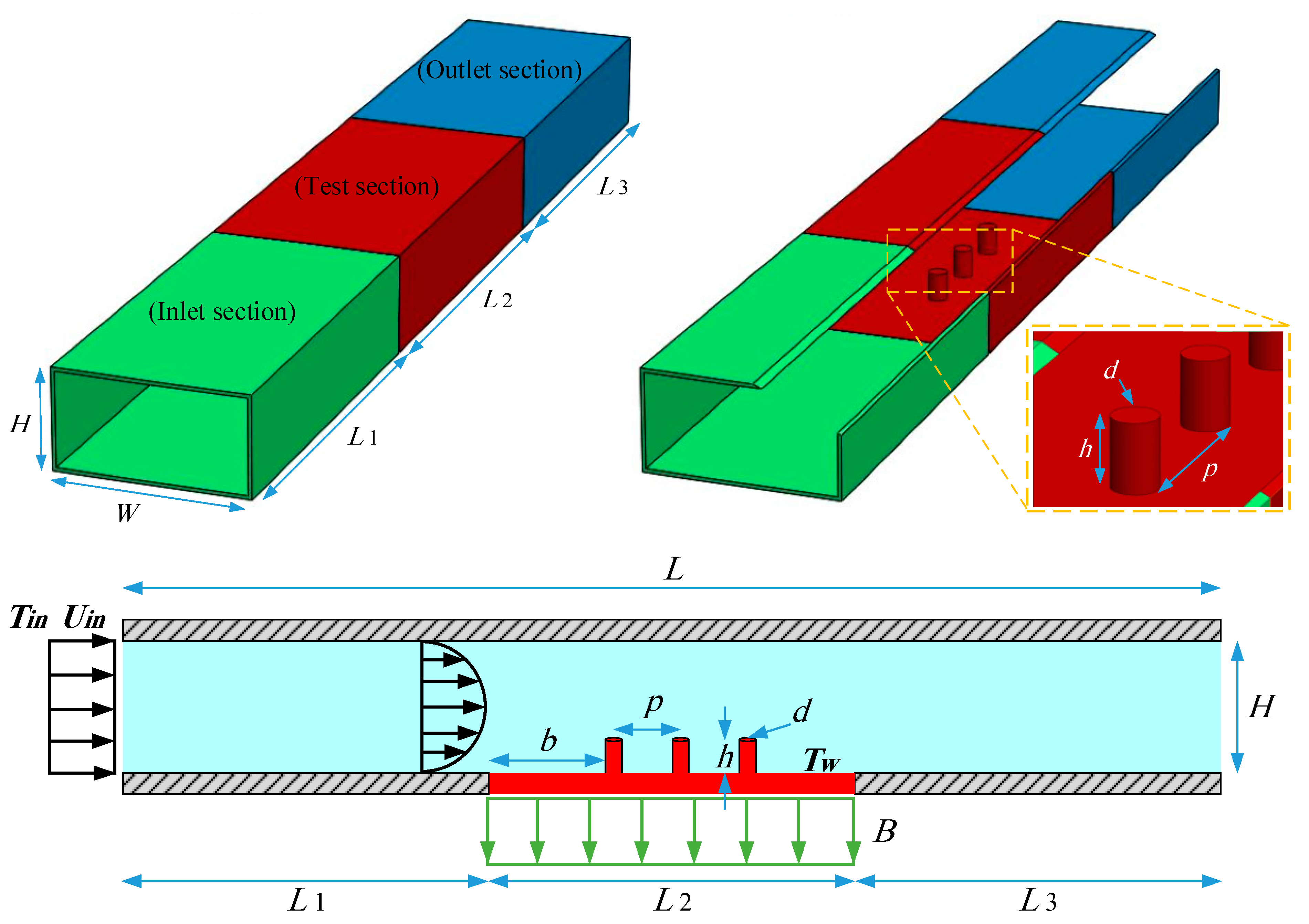
Figure 1. Schematic representation of the physical model.
Processes 09 01278 g001
Figure 2. Grid independency: Nuav values calculated on the bottom wall of microchannel versus R e .
Processes 09 01278 g002
Figure 3. Contrasting the averaged Nusselt number of the study.
Processes 09 01278 g003
Figure 4. Temperature profile for the last rib across the midplane zone of channel prone to B = 0.2 T.
Processes 09 01278 g004
Figure 5. Temperature profile for the last rib across the midplane zone of channel prone to B = 0.5 T.
Processes 09 01278 g005
Figure 6. Velocity profile for the last rib across the midplane zone of channel prone to B = 0.2 T.
Processes 09 01278 g006
Figure 7. Temperature profile for the last rib across the midplane zone of channel prone to B = 0.5 T.
Processes 09 01278 g007
Figure 8. Action of magnetic field on (a) Nuav, (b) pressure drop, (c) friction factor, and (d) PEC, for h = 10 μm, p = 1.0 μm, d = 8 μm, and different R e .
Processes 09 01278 g008aProcesses 09 01278 g008b
Figure 9. The impact of varied inlet corrugation pitches on: (a) Nuav, (b) pressure loss penalty, (c) friction factor coefficient, and (d) thermal and hydraulic PEC index, for the microchannel with h = 10 μm and d = 8 μm subjected to magnetic field with B = 0.5 T and different Re.
Processes 09 01278 g009
Figure 10. The impact of varied corrugation heights on: (a) Nuav, (b) pressure loss penalty, (c) friction factor coefficient, and (d) thermal and hydraulic PEC index, for the microchannel with p = 1.5 μm and d = 8 μm subjected to magnetic field with B = 0.5 T and different Re.
Processes 09 01278 g010
Figure 11. The impact of varied corrugation diameters on: (a) Nu, (b) pressure reduction penalty, (c) friction factor coefficient, and (d) thermal and hydraulic PEC index, for the microchannel with p = 1.5 μm and h = 15 μm subject to magnetic field with B = 0.5 T and different Re.
Processes 09 01278 g011aProcesses 09 01278 g011b
Table 1. Geometrical attributes of the flow section.
Constants L 1 = 4   mm L 2 = 4   mm L 3 = 4   mm L = 12   mm
D h = 8   μ m g = 9.81   m / s 1 H = 40   μ m W = 70   μ m
Modelh (μm)p (mm)b (mm)d (μm)
Case 1101.01.010
Case 2101.50.510
Case 3151.50.510
Case 4201.50.510
Case 5151.50.58
Case 6151.50.512
Table 2. Thermophysical properties of the particle and fluid samples.
Materialρ (kg/m3)cp (J/kg·K)k (W/m·K)
Pure Water997.141790.6136.2
Al2O3397076540
Nanofluidρ (kg/m3)cp (J/kg·K)k (W/m·K)
dnp = 25 nmdnp = 45 nmdnp = 100 nm
CMC(0.5%) + 1.0% Al2O31013.541210.62620.62110.6157
CMC(0.5%) + 1.5% Al2O31040.540120.6600.6480.6356
Table 3. System-state equations.
. ( ρ n f V m ) = 0 Mass conservation equation:
. ( ρ n f V m V m ) = P + . ( μ n f V m ) + ( M . ) . B Momentum equation
. ( ρ n f c V m T ) = . ( k n f T ) +   μ 0 ( M . ) . H Energy conservation equation
τ = K γ ˙ n Power-law non-Newtonian model
. B   = 0 Maxwell equations
× H = 0
B =   μ 0 ( M + H )
Publisher’s Note: MDPI stays neutral with regard to jurisdictional claims in published maps and institutional affiliations.