Abstract
This work presents an experimental and modelling evaluation of the preferential oxidation of CO (CO PROX) from a H2-rich gas stream typically produced from fossil fuels and ultimately intended for hydrogen fuel cell applications. A microchannel reactor containing a washcoated 8.5 wt.% Ru/Al2O3 catalyst was used to preferentially oxidise CO to form CO2 in a gas stream containing (by vol.%): 1.4% CO, 10% CO2, 18% N2, 68.6% H2, and 2% added O2. CO concentrations in the product gas were as low as 42 ppm (99.7% CO conversion) at reaction temperatures in the range 120–140 °C and space velocities in the range 65.2–97.8 NL gcat−1 h−1. For these conditions, less than 4% of the H2 feed was consumed via its oxidation and reverse water-gas shift. Furthermore, a computational fluid dynamic (CFD) model describing the microchannel reactor for CO PROX was developed. With kinetic parameter estimation and goodness of fit calculations, it was determined that the model described the reactor with a confidence interval far greater than 95%. In the temperature range 100–200 °C, the model yielded CO PROX reaction rate profiles, with associated mass transport properties, within the axial dimension of the microchannels––not quantifiable during the experimental investigation. This work demonstrates that microchannel reactor technology, supporting an active catalyst for CO PROX, is well suited for CO abatement in a H2-rich gas stream at moderate reaction temperatures and high space velocities.
1. Introduction
Hydrogen (H2) is widely considered as the fuel of the future in terms of meeting sustainability and carbon emissions reduction goals, renewable energy storage potential, and supporting various end-uses in industrial and transport sectors. At present, the global H2 production capacity is still dominated by fossil fuel resources [1]. During the transition from fossil-based H2 to renewable ‘green’ H2 energy, there are certain requirements that pertain to H2 purity. The reason is that H2 from fossil fuels contains many impurities, including, but not limited to, CO, CO2, CH4, N2, and H2O.
Advancements made in the field of proton exchange membrane fuel cells (PEMFC), including their scale up, have made it possible to generate power with zero emissions at the point of generation, using H2 as a fuel source [2,3]. More specifically, if a H2 stream from fossil fuel origin is intended to be used in PEMFC, the CO (harmful to Pt catalyst) needs to be eliminated from the H2 gas stream to ensure the long-term performance stability of PEMFC [3]. PEMFC cells with Pt and Pt-Ru anode catalysts have the ability to tolerate CO at concentrations of <10 ppm and <100 ppm, respectively [4,5,6]. Several CO abatement techniques have been proposed in the literature. Membrane separation and pressure swing adsorption (PSA) enable H2 purities greater than 99.99% to be achieved. Unfortunately, the durability of membranes is limited because of low mechanical strength and vulnerability to H2 embrittlement. On the other hand, the design of PSA purification units is fairly complex; it involves the use of high compression ratios and multicolumn adsorption systems. CO preferential oxidation (CO PROX) has been identified as a cost-effective CO abatement technology [1]. Arzamendi et al. [7] suggested that CO PROX is a simple process, supporting compact reactor technologies, and it could be used to convert CO in a H2-rich gas stream in small-scale fuel processors and in on-board applications. CO PROX has been investigated using a variety of different H2 gas mixtures and various heterogeneous catalysts.
The CO PROX reaction has high turnover rates in supported noble metals (e.g., Au, Pt, Pd, and Ru) and transition metal oxides (e.g., CuO). Au-based catalysts are efficient at reaction temperatures <100 °C [8,9,10,11]; however, they are prone to particle sintering [10,12,13]. Transition metal catalysts are efficient and inexpensive [13], but their catalytic activity is usually lower than that of noble metal catalysts at moderate reaction temperatures of 100–200 °C [12]. Ru-based catalysts have the advantage of being more stable and efficient than Pt, Pd, Rh, and Co [14,15]. Using a 0.7 wt.% Ru/α-Al2O3 catalyst, Kim and Park [16] recorded the reduction of CO to as low as 10 ppm in a feed containing 1 vol.% CO, 1 vol.% O2, 50 vol.% H2, and other components of CO2, H2O, and He, at reaction temperatures of 110–140 °C. Han et al. [14] studied CO PROX on a 5 wt.% Ru/Al2O3 catalyst, and reported that an increase in temperature from 125 to 175 °C resulted in a CO conversion increase from less than 20% to 88% at an O2/CO molar ratio of 1. Further increases in temperature at the same molar ratio resulted, first in a decrease in CO conversion, and then in an increase, due to the reverse water-gas shift (RWGS) and methanation reactions, respectively.
In reactor technologies for CO PROX, it is important to determine the fuel processor’s throughput and CO conversion efficiency. Many experimental studies of CO PROX were successfully performed using fixed-bed reactors. Heat and mass transfer limitations due to uneven temperature distributions and large pressure drops within the reactor are challenges associated with these reactors, especially when upscaled. In the case of smaller-scale fuel processors, a compact and integrated device, which can operate at near-isothermal conditions, would be ideal for H2 processing for PEMFC applications. Microchannel reactors are well suited to satisfy these requirements due to their reduced physical dimensions (improved mass transport), compactness, and––if fabricated from high thermal conductivity materials––capability for near-isothermal operation [7,17]. Microchannel technology has been applied for the CO PROX process in the past. Snytnikov et al. [18] studied the CO PROX reaction in 26 parallel microchannels, each coated with a 5 wt.% Cu/CeO2-x catalyst, and designed to deliver H2 to a 100 W PEMFC. To support fast turnover rates, reaction temperatures of 220–240 °C were used to reduce an initial CO concentration of 1.5 vol% to within the range 2–10 ppm, at a high space velocity (250 NL gcat−1 h−1) and an O2/CO ratio of 1.5. Galletti et al. [4] evaluated a microchannel reactor coated with a Rh/(50 wt.% γ-Al2O3 + 50 wt.% zeolite) catalyst for CO PROX. They recorded similar observations to those of Snytnikov et al. [18]. For an O2/CO ratio of 1.5, the CO concentration in the H2 gas stream was reduced from 1 vol.% to <10 ppm at (albeit slightly lower) reaction temperatures of 140–220 °C and a space velocity of 60 NL gcat−1 h−1.
To date, computational fluid dynamic (CFD) modelling has not often been reported for CO PROX processes. Uriz et al. [19] studied CO PROX in a microchannel reactor coated with an Au/CuOx-CeO2 catalyst, using representative kinetic rate expressions, and established that microchannel reactor technology could reduce CO levels to tens of ppm under specific conditions of reaction temperature and O2/CO ratios. Arzamendi et al. [7] carried out 3D simulations of CO PROX over CeCu and Au/CeFe catalysts in thermally coupled microchannels, and microslits. The CeCu catalyst was found to reduce CO to 10–100 ppm in the product gas, in the temperature range 170–200 °C and at space velocities of 10 000–50 000 h−1. In follow-up CFD work, Laguna et al. [20] established that due to the endothermic nature of the RWGS reaction, operating a CO PROX reactor at temperatures >220 °C may result in a phenomenon where the CO conversion decreases with increasing reaction temperature, despite high CO oxidation activity. Reaction kinetics of a CuOx/CeO2 catalyst were used to describe the multi-reaction system.
This paper presents a comprehensive experimental and modelling evaluation of a microchannel reactor, supporting a washcoated 8.5 wt.% Ru/Al2O3 catalyst, for the CO PROX process. First, the performance of the experimental reactor is assessed based on the reaction temperature and space velocity. There is a critical analysis of suitable operating conditions of the microchannel reactor, supporting high CO conversion and selectivity. The RWGS is a determining factor in the higher temperature range of CO PROX operation. Secondly, a CFD model is developed to assist in the evaluation of reaction and mass transport characteristics within the microchannels. It includes regressed reaction kinetics for CO oxidation and the RWGS. The model is validated on the reactor’s experimental performance for CO PROX. CFD modelling is a powerful theoretical tool that has been used in chemical reaction engineering applications to determine process characteristics that are not quantifiable experimentally, especially in compact thermo-catalytic devices, such as microchannel reactors [21]. Due to the non-linearity of the CFD model, the popular coefficient of determination (R2) is not applicable here to determine the model’s goodness of fit to the experimental data. Instead, the bootstrap statistical method is applied to determine if the model fits the experimental data with a confidence interval >95%.
2. Materials and Methods
This section describes the microchannel reactor, the catalyst used in the washcoating of the microchannels, other experimental apparatus, and the procedure followed to obtain experimental data for CO PROX in the microchannel reactor.
2.1. Microchannel Reactor Design
The microchannel reactor was designed and manufactured in collaboration with Fraunhofer-IMM (Mainz, Germany). The reactor was fabricated from SS314 steel (German steel classification 1.4841); it consisted of one microchannel plate and one cover plate (both 2 mm thick). The microchannel plate supported 80 microchannels and two fluid distribution manifolds (Figure 1a). The geometric features of the microchannels and the fluid distribution manifolds were imprinted according to a wet chemical etching technique [22]. The non-catalyst-coated microchannels had dimensions of W = 450 μm, H = 150 μm, and L = 5 cm (Figure 1b). The catalyst coating procedure described by O’Connell et al. [22] was followed, and the reactor was laser welded with the cover plate. Finally, the microchannel reactor was fitted with two 1/8 inch stainless steel pipes for inlet and outlet gas flows (Figure 2).

Figure 1.
Illustrations of (a) the microchannel reactor plate with 80 microchannels and two fluid distribution manifolds chemically etched; (b) the dimensions of a single uncoated microchannel. Adapted with permission from N. Engelbrecht, S. Chiuta, R.C. Everson, H.W.J.P. Neomagus, D.G. Bessarabov, Chemical Engineering Journal; published by Elsevier, 2017 [23].
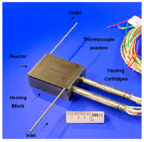
Figure 2.
The experimental microchannel reactor with inlet and outlet piping, heating block, and cartridge heaters. Reproduced with permission from S. Chiuta, R.C. Everson, H.W.J.P. Neomagus, D.G. Bessarabov, International Journal of Hydrogen Energy; published by Elsevier, 2015 [24].
2.2. Catalyst Preparation and Washcoating
A commercial 8.5 wt.% Ru-Cs/Al2O3 catalyst (10010™) was obtained from Acta S.p.A (Crespina, Italy). A Brunauer–Emmet–Teller surface area analysis revealed that the catalyst supported a surface area of 113 m2 g−1 and pore volume of 0.30 cm3 g−1. O’Connell et al. [22] described the catalyst preparation, washcoating, drying, and calcination procedures that were used to apply the catalyst to the microchannels, with a resultant porous catalyst layer thickness of ~40 μm. Ultimately, the reactor contained 92 mg of catalyst.
2.3. Experimental Apparatus
The reactor was supported by a heating block, which makes provision for two Watlow FIREROD® 300 W heating cartridges. The reactor temperature was measured using two K-type thermocouples (2 mm OD) positioned below the reactor wall. Three Brooks SLA5850 flow controllers (Hatfield, PA, USA), controlling the flow rates of CO/H2, O2/N2 and CO2 gas supplies, were used to obtain the desired composition of the feed gas. The flow rate of the product gas was measured using a bubble flow meter at room conditions, and normalised during data processing. Prior to quantifying its composition, the product gas was dried using silica beads. The gas composition was determined by gas chromatography (GC), using an online SRI 8610 GC (Torrance, CA, USA), fitted with a HayeSep D column and two molecular sieve-13X columns. The GC instrument was fitted with a helium ionisation detector and two thermal conductivity detectors. The GC was capable of detecting CO levels up to a limit of 20 ppm.
2.4. Experimental Procedure
Prior to the experiments, the microchannel reactor was heated to 400 °C under a N2 flow of 32.6 NL gcat−1 h−1. The Ru catalyst was reduced in a flow of H2 at the same flow rate for 1 h, then cooled under a subsequent N2 flow. For each experiment, a one-factor-at-a-time approach was followed to vary the operational parameters of the reaction temperature and the space velocity. A gas mixture simulating a dry water–gas shift (WGS) reactor reformate, consisting of 1.4 vol.% (1.4 × 10⁴ ppm) CO, 10 vol.% CO2, 68.6 vol.% H2, 2 vol.% O2, and N2 as balance, was mixed and used as the feed gas for the reactor. The reaction temperature was varied over the range 80–200 °C (in 20 °C increments). Space velocities of 32.6–130.4 NL gcat−1 h−1 (in 32.6 NL gcat−1 h−1 increments) were used in the evaluation of the reactor performance. Each experiment was conducted at a constant temperature and space velocity, over a period of 2.5 h of steady-state operation. The product gas flow rate and GC sample were quantified every 15 min, and averaged across the 10 data points for that particular experiment.
2.5. Performance Criteria
In a CO PROX reaction system, CO oxidation (Equation (1)), H2 oxidation (Equation (2)), and WGS (Equation (3)) reactions are possible:
In the temperature range 80–200 °C, no CH4 was detected in the product gas. The effects of any CO or CO2 methanation reactions were therefore disregarded. Throughout this work, the CO conversion (Equation (4)) and CO selectivity (Equation (5)) were used as performance criteria:
3. CFD Modelling Procedure
A CFD model was developed using COMSOL Multiphysics® V4.4 software (Burlington, MA, USA) [25]. Steady-state modelling was used to characterise transport phenomena in the microchannel reactor. This section describes the development of the CFD model, and the determination of its goodness of fit to the experimentally evaluated reactor for CO PROX.
3.1. Model Geometry
The model geometry, originally developed by Chiuta et al. [21], represents a single wall-coated microchannel, and is truncated along its central longitudinal plane of symmetry for model simplification (Figure 3). The model geometry incorporates a free-fluid region, and a porous catalyst layer (thickness 40 μm). To accurately compute sharp species concentration gradients in the porous catalyst (due to fast reaction kinetics), its meshing elements are smaller than those in the free-fluid region, which supports slower convective and diffusive mass transfer. To evaluate the effect of mesh element sizes on the accuracy of the CFD model, a mesh dependency study was carried out. It was found that 7.59 × 10⁴ prismatic elements (illustrated in Figure 3) described the model with acceptable accuracy, while minimising computational time.
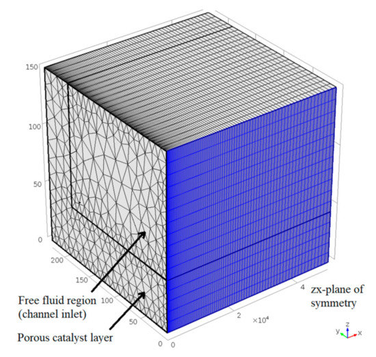
Figure 3.
Discretised model geometry, illustrating the microchannel’s free fluid and porous catalyst regions, and the central longitudinal plane of symmetry (axes in µm). Adapted with permission from S. Chiuta, R.C. Everson, H.W.J.P. Neomagus, L.A. Le Grange, D.G. Bessarabov, International Journal of Hydrogen Energy; published by Elsevier, 2014 [21].
3.2. Model Assumptions and Boundary Conditions
Because the 80 microchannels in the reactor are identical, equal partitioning of the gas flow was assumed among them—hence, only a single microchannel was modelled. Any homogeneous reactions were disregarded, as the microchannel’s dimensions (W = 370 μm in the free-fluid region) are such that flame propagation of H2 and CO flames is not possible. Therefore, the chemical reactions were assumed to be catalytic and take place exclusively within the catalyst layer. The gas was assumed to be ideal, its flow compressible (Mach < 0.3) and laminar (Re << 2.1 × 10³). Temperature-dependent gaseous physical properties, i.e., heat capacities, thermal conductivities, and viscosities, were calculated using correlations from the Korean Thermophysical Properties Data Bank, and applied to the gaseous mixture on an averaged molar basis [26].
The composition of the model gas mixture (Section 2.4) was imposed at the inlet of the free-fluid region. The average linear inlet velocity was calculated using the volumetric flow rate through a single microchannel and the channel’s cross-sectional area. The plane of symmetry (indicated in Figure 3) refers to the microchannel’s central longitudinal axis, and continuity in the normal direction to the plane was imposed in species concentration, temperature, pressure, and velocity (zero gradients across the plane of symmetry). Further fluid continuity was assumed at the interface between the porous catalyst and the free-fluid region. No species flux was imposed in the normal direction on the reactor wall, and a no-slip boundary condition (zero velocity) was used on the walls of the microchannel. Atmospheric pressure conditions and continuity were assumed at the free-fluid region’s outlet. These conditions are expressed mathematically in Table A2 (Appendix A).
3.3. Governing Equations
The main differential equations that govern the microchannel reactor system are summarised in Table A1 (Appendix A). In the CFD model, mass transfer is represented by both convection and diffusion. The Navier–Stokes equations describe momentum conservation in the free-fluid region, while in the catalyst domain the Brinkman–Forchheimer–Darcy model is used. For describing diffusion, the Maxwell–Stefan diffusion model, which incorporates binary gas diffusion coefficients, is used. These coefficients are estimated using the Fuller–Schettler–Giddings equation [27], and were subsequently adapted to the catalyst layer using the Bruggeman correlation as a result of the catalyst’s porosity [23]. Due to the catalytic reactions taking place within the porous catalyst layer, the term describing species formation/consumption was added to the catalyst layer’s species continuity equation.
The oxidation reaction kinetics used in the CFD model (Equations (6) and (7)) were reported by Baughman et al. [28], who employed a parameter estimation method to optimise kinetic parameters from different reaction models in the literature to describe CO PROX processes (including using Ru/Al2O3 catalysts). However, the kinetic rate equation and parameters for the reversible WGS reaction were not reported for Ru/Al2O3. These were adapted from Garbis et al. [29], who studied CO selective methanation on a Ru/Al2O3 catalyst (Equations (8) and (9)).
CO oxidation:
H2 oxidation:
WGS reaction:
3.4. Equilibrium Calculations
To assess the thermodynamic equilibrium of the CO PROX system, equilibrium calculations were perform using Aspen Plus V8.6. The Peng–Robinson fluid property package was selected for the calculations. All the reactants (H2, O2, CO, and CO2), as well as N2, CH4, and H2O, were considered as possible products in the Gibbs free energy minimisation calculation. In the temperature range 80–200 °C, equilibrium showed a practically complete conversion of CO and O2, whereas the H2 conversion was >70%, mainly due to the methanation reaction with 10 vol.% CO2 in the feed gas.
3.5. Parameter Estimation Procedure
Parameter estimation (regression) is an important aspect in the determination of reaction kinetics—it ensures the accurate representation of an experimental catalytic reaction system, using computations. Parameter estimation aims at minimising the sum of squared differences (objective function) between the experimental and simulated CO conversions, for the range of reaction temperatures and space velocities in the CO PROX process. Modelling a non-linear chemical process with interdependence on the reaction temperature and space velocity is a computationally intensive task. Furthermore, initial parametric values are of great importance during regression as a result of possible local minima in the objective function [30,31].
To determine the initial values for parametric estimation, the kinetic parameters to which CO conversion was most sensitive during CO PROX were identified. The kinetic parameters selected for regression were those of the CO oxidation rate (a, kC, and EC, in Equation (6)) and the reversible WGS rate (kD and ED, in Equation (8)). The effects of the H2 oxidation reaction (Equation (7)) were minimal in the temperature range studied (80–200 °C), with the H2 conversion varying between 3% and 6.5%. The kinetic rate parameters published by Baughman et al. [28] fitted the experimental data well, and there was no justification (limited certainty) to further regress the kinetic parameters of H2 oxidation in this temperature range. The five kinetic parameters for CO oxidation and the reversible WGS were manually adjusted based on the observed trends of CO conversion within the 80–200 °C temperature range. Subsequently, the estimated kinetic parameters were later used as initial values in the regression, using the Nelder–Mead optimisation algorithm in the COMSOL Multiphysics® software package.
3.6. Solution Method
The COMSOL Multiphysics® V4.4 software package was used to develop and evaluate the CFD model, supported on a computer with 256 GB DDR3 RAM and a 2.9 GHz (18 core-Intel) processor. Theoretical CO conversions were calculated using a parametric sweep for all combinations of reaction temperatures and space velocities. The direct solver, PARDISO, was used to solve the set of differential equations within a relative tolerance of 0.01. Finally, to regress the identified kinetic rate parameters mentioned in Section 3.5, the Nelder–Mead optimisation algorithm was used to minimise the sum of squared differences between the experimental and model-predicted CO conversions.
3.7. Goodness of Fit Analysis Using the Bootstrap Method
Due to the non-linear nature of this chemical reaction engineering model, the R2 is not appropriate as a goodness of fit measure of the CFD model to the experimental data [32]. Similarly, using an F-test to test for the overall significance of a non-linear model may lead to inappropriate results. In addition to the problem of non-linearity, the residuals ) between the model and experiments must be uncorrelated, normally distributed, and have a zero mean and constant variance for the F-test to be valid. The validity of the F-test relies on the asymptotic properties of the test, which leads to less reliable results in experiments with small sample sizes. It is clear from Figure A1 (Appendix B) that none of these conditions was satisfied for the limited data set (24 data points) used in the model developed for the present work. Therefore, to determine how adequately the model describes the relationship between the CO conversion performance at different reaction temperatures and space velocities, a bootstrap method will be used.
The bootstrap method is a resampling method that simulates the sampling distribution of a statistic from an observed sample. It is a relatively simple method that has been used in many applications to estimate parameters or confidence intervals [33]. A summary of the bootstrap method has been reported by Wehrens et al. [34].
Formally, the following hypothesis was tested:
in which it is assumed that no relationship exists between the covariates (i.e., g temperatures and h space velocities) and CO conversions (). Assuming that the null hypothesis is true, a bootstrap sample of the sum of squared residuals of size B = 100 000 is generated from the original 24 data points (CO conversions at 100–200 °C and 32.6–130.4 NL gcat−1 h−1) using an algorithm run using the R software. The test was then applied at a confidence level of 95% (α = 0.05).
4. Results and Discussion
4.1. Experimental Results
The experimental results of CO PROX in the microchannel reactor coated with the Ru/Al2O3 catalyst are now reported. Special focus is placed on the influence of operational parameters (reaction temperature and space velocity) on the reactor’s ability to provide high CO conversion and selectivity.
4.1.1. Effects of Reaction Temperature and Space Velocity on CO Conversion
In Figure 4a, the CO conversion achieved within the microchannel reactor is presented for the reaction temperature range 80–200 °C (on the x-axis) and for the space velocities of 32.6–130.4 NL gcat−1 h−1. Upon first observation, the CO conversion due to oxidation is strongly dependent on the reaction temperature. The operating temperature range can be delineated into three temperature regions: 80–120 °C, 120–160 °C, and 160–200 °C. In the low-temperature region, the substandard CO conversions (<65%) observed at 100 °C, and for space velocities of 65.2–130.4 NL gcat−1 h−1, can be attributed to the kinetic limitations of the CO oxidation reaction. To illustrate this kinetic limitation for the lowest space velocity (32.6 NL gcat−1 h−1), an additional experiment was performed at 80 °C; it resulted in a 38.5% CO conversion. The reactor performance was not evaluated for 65.2–130.4 NL gcat−1 h−1 at 80 °C because it is recognised that much lower CO conversions would be obtained compared to the 38.5% CO conversion for 32.6 NL gcat−1 h−1. In the temperature range 120–160 °C, CO conversions were much closer to the equilibrium conversions for CO oxidation, especially at 140 °C, where the CO conversions were >98.7% for all the space velocities investigated. These intermediate reaction temperatures support high CO conversion rates, while no significant influence of the endothermic RWGS was observed. At higher reaction temperatures (180–200 °C), a decrease in the CO conversion was observed—at 180 °C only for the lowest space velocity (32.6 NL gcat−1 h−1) and at 200 °C for all the space velocities—and can be attributed to the occurrence and effect of the RWGS reaction. The high concentrations of H2 (68.6 vol.%) and CO2 (10 vol.%) in the feed gas resulted in the formation of sufficient CO and H2O to decrease the overall CO conversion.
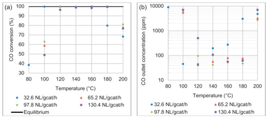
Figure 4.
Effects of reaction temperature and space velocity on (a) CO conversion and (b) CO product concentration. Feed composition: 68.6 vol.% H2, 1.4 vol.% CO, 10 vol.% CO2, 2 vol.% O2, and 18 vol.% N2.
In Figure 4b, the product CO concentration is presented, also as a function of temperature on the x-axis, and for the four space velocities applied here. The increased contact time of the 32.6 NL gcat−1 h−1 flow condition gave a satisfactory CO conversion (99.7%) and CO outlet concentration (45.2 ppm), even at a temperature as low as 100 °C. At 100 °C, the kinetic limitations and increased gas throughput for space velocities of 65.2–130.4 NL gcat−1 h−1 mean that CO concentrations in the order of 5118–6990 ppm were obtained in the product. It can be reasoned that the kinetic limitations are clearly evident, when considering that upon doubling the residence time of the feed gas within the reactor (32.6 NL gcat−1 h−1 vs 65.2 NL gcat−1 h−1), the CO conversion increased by a factor of 1.69 (from 58.9% to 99.7% CO conversion, with a 5781 ppm CO difference). CO product concentrations as low as 41.4–42.2 ppm were achieved at 120 and 140 °C, respectively, for the two intermediate space velocities.
At 180 °C, some breakthrough in the CO conversion for the lowest space velocity was evident. A conversion of 79.8% and CO product concentration of 3.033 × 10³ ppm were achieved, which is unsatisfactory, considering that CO conversions >99% were achieved in the intermediate temperature range. At 200 °C, significant effects of the endothermic RWGS reaction resulted in a noticeable increase in CO product concentrations for all the space velocities investigated here: 2698–6690 ppm. Consequently, 200 °C was the high-temperature boundary for this experimental investigation.
Overall, it was observed that for each space velocity its lowest product CO concentration was 45.2 ppm (32.6 NL gcat−1 h−1), 41.4 ppm (65.2 NL gcat−1 h−1), 42.2 ppm (97.8 NL gcat−1 h−1), and 55.9 ppm (130.4 NL gcat−1 h−1) at temperatures of 100, 120, 140, and 160 °C, respectively. Therefore, with increasing space velocity, the reaction temperature required to achieve the best CO conversion shifted towards higher reaction temperatures due to the kinetic constraints of CO oxidation, before showing the influence of the RWGS reaction. After the set of experiments were concluded, several experimental data points that yielded low ppm concentrations of CO (<50 ppm) in the product gas stream were repeated. It was found that experiments were reproducible with a variation in the CO outlet concentration of less than 16 ppm.
4.1.2. Effects of Reaction Temperature and Space Velocity on CO Selectivity
Ideally, the CO PROX process is designed to support only the CO oxidation reaction. However, in many cases, the reaction temperature for CO PROX is such that H2 oxidation and the reversible WGS reactions also occur (although they are undesirable). The WGS reaction has the ability to convert CO and H2O to CO2 and H2 (Equation (3)). However, H2O in the reacting stream is required, which, in this specific case, can only be provided when some H2 is oxidised to H2O. It is for this reason that CO oxidation is considered to be the main CO-consuming reaction, and the H2 oxidation and reversible WGS are secondary reactions. Despite the relatively high H2 content in the feed gas (68.6%), the H2 consumption did not exceed 6.5% for any of the operational conditions investigated. H2 oxidation consumes O2 according to the same reaction stoichiometry as the CO oxidation reaction. The selectivities towards CO oxidation were between 17.7% and 50.3% (Figure 5). Incidentally, the lowest CO selectivities (17.7–27.0%) were observed for the lowest space velocity (32.6 NL gcat−1 h−1). It is therefore evident that the H2 oxidation reaction requires longer residence times to make a significant impact on the H2 conversion in the 80–200 °C temperature range. This is a desirable prospect, because higher space velocities decrease the gaseous residence time within the reactor, improve the feed gas throughput (processing rate), and limit H2 loss through its oxidation.
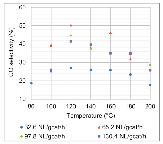
Figure 5.
Effects of reaction temperature and space velocity on the CO selectivity. Feed composition: 68.6 vol.% H2, 1.4 vol.% CO, 10 vol.% CO2, 2 vol.% O2, and 18 vol.% N2.
There appeared to be a trend that the CO selectivity was the highest for all the space velocities at the 120 °C reaction temperature. For the space velocities of 65.2–130.4 NL gcat−1 h−1, CO selectivities as high as 41.5–50.3% were obtained. At low temperature (100 °C), the kinetic limitations of CO oxidation for space velocities of 65.2–130.4 NL gcat−1 h−1 yielded lower CO selectivities (25.7–39.2%) than at 120 °C. A similar trend was observed in terms of unsatisfactory CO conversions and CO product concentrations at 100 °C. At higher temperature (180 °C), CO conversions and CO product concentrations (<77 ppm) were still satisfactory for the space velocities of 65.2–130.4 NL gcat−1 h−1; however, increased H2 oxidation negatively affected the CO selectivity (31.8–34.8%). At 200 °C, additional CO formation due to the RWGS reaction further decreased the CO selectivities.
4.2. Modelling Results
The literature values of the kinetic parameters for the CO PROX reactions resulted in a model that did not accurately describe the experimental CO conversions. The parametric estimation method was therefore required. This section describes, first, the estimation of kinetic parameters, and the model’s validation and goodness of fit to the experimental CO conversions. This is followed by addressing the evolution of reaction rates and species concentrations within the modelled catalytic microchannel.
4.2.1. Estimation of Kinetic Parameters
Kinetic parameter estimation and regression (values tabulated in Table 1) were guided by the effects of reaction kinetics on CO conversion in different temperature regions. In the low-temperature region (80–120 °C), CO oxidation was the most significant reaction affecting the CO conversion. The reaction order with respect to CO, pre-exponential constant and activation energy in the CO oxidation reaction rate (a, kC, and EC) were manually adjusted such that simulated CO conversion trends followed those observed experimentally. In the model gas feed for this oxidation process, CO was fed as a limiting reactant while O2 was fed in excess. The CO oxidation reaction rate (Equation (6)) was therefore assumed to proceed with a first-order kinetic rate dependence on CO concentration (a = 1). The values published by Baughman et al. [28] present a value that renders the CO oxidation rate almost independent of CO concentration (a = 0.01). The temperature dependence of CO conversion (Figure 4) in the low-temperature range suggests that EC was much stronger than what is suggested by the published activation energy. The EC was then increased, while also adjusting the kinetic rate constant to represent accurate kinetic turnover rates (and subsequently accurate CO conversion).

Table 1.
Results of parametric estimation of selected kinetic rate constants of CO oxidation and WGS reactions (Equations (6) and (8)).
When only the two oxidation reactions of CO and H2 are taken into account, misrepresentation of the experimental data at reaction temperatures >160 °C is apparent (Figure 6). In this higher temperature range, it is understood that the RWGS reaction is responsible for the decrease in the CO conversion. Similar reasoning as in the case of the CO oxidation reaction was applied to alter the reversible WGS reaction’s activation energy (ED) and pre-exponential constant (kD) to achieve a decreasing trend of CO conversion at temperatures of 180–200 °C. Importantly, parameter estimation was performed taking into consideration the effects of all temperatures and space velocities investigated. Figure 6 presents the case of the two oxidation reactions, neglecting the reversible WGS reaction for only the lowest space velocity.
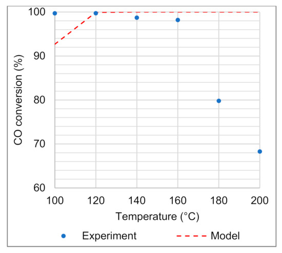
Figure 6.
CO conversion measured experimentally and modelled using only CO and H2 oxidation reactions (neglecting the reversible WGS), for a space velocity of 32.6 NL gcat−1 h−1.
The Nelder–Mead optimisation algorithm was only applied to the regression of kC, kD, EC, and ED. The regressed kinetic parameters are also summarised in Table 1. Small changes were observed between the values of the manually estimated and the regressed kinetic parameters. For regression calculations in multi-parametric non-linear models, it is essential to select suitable initial values for the regression calculations. Ultimately, the Nelder–Mead optimisation algorithm minimised the sum of squared residuals by 14.6%, compared to the manually estimated kinetic parameters.
4.2.2. Model Validation
The CO conversions modelled at temperatures between 100 and 200 °C followed the same trends as observed experimentally. The optimised activation energy of the CO oxidation reaction (EC = 72.15 kJ mol−1) was found to be twice the magnitude of the one reported by Baughman et al. [28]. This increase in magnitude accounted for the rapid increase in CO conversions observed between 100 and 120 °C for space velocities of 65.2–130.4 NL gcat−1 h−1 (Figure 7b–d). Furthermore, the model predicted high CO conversions (>90%) at temperatures between 120 and 180 °C, with exceptions at 120 °C for the highest space velocity of 130.4 NL gcat−1 h−1 (86.0% CO conversion) and at 180 °C for the lowest space velocity of 32.6 NL gcat−1 h−1 (83.3% CO conversion). In these two conditions, the model deviations from the high CO conversions were not unexpected, as the experimental data showed values for the CO conversion of 96.4% and 79.8%, respectively. The modelling results in this temperature range fitted most of the results obtained experimentally, indicating that the model could be used for the selection of suitable operating conditions of the microchannel reactor. From the model, temperatures between 140 and 180 °C and space velocities between 65.2 and 97.8 NL gcat−1 h−1 could be selected as the most favourable operating conditions.
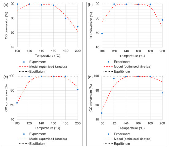
Figure 7.
CFD model validation (incorporating CO oxidation, H2 oxidation, and reversible WGS reactions) to experimental data of CO conversion, in the temperature range 100–200 °C, and for space velocities of (a) 32.6, (b) 65.2, (c) 97.8, and (d) 130.4 NL gcat−1 h−1.
In the high-temperature regime (180–200 °C), the model suitably predicted the effect of the RWGS reaction, with a decrease in the CO conversion. This effect was observed for all the four space velocities investigated, especially at 200 °C. Typically, the activation energy of the reversible WGS (74.74 kJ mol−1) has to be higher than that of the CO oxidation reaction (72.15 kJ mol−1) for the model to account for the stronger effect of the RWGS reaction at these temperatures. It was noticed that the model under-predicted (by 15.6% in the CO conversion) the strong effect of the RWGS reaction at 200 °C for the highest space velocity (130.4 NL gcat−1 h−1). This was the largest discrepancy between the model-predicted CO conversion and conversion obtained with the experimental reactor. Here, it has to be taken into account that the Nelder–Mead optimisation calculations considered the errors between the model-predicted values and the experimental data for all the space velocities and across the range of temperatures to arrive at the minimum sum of squares solution.
4.2.3. Goodness of Fit Results
The bootstrap method described in Section 3.7 was successfully applied to establish whether the modelled CO conversions were adequately describing the experimental findings (>95% confidence level). Two cases are presented in Table 2: CFD modelling conducted (i) using the published kinetic parameters and (ii) using the regressed parametric values. Table 2 shows the p-values obtained for bootstrap sample sizes of B = 1.0 × 10⁵.

Table 2.
p-Values obtained using the bootstrap method.
These results show that the fitted model with the published parametric values are unable to capture the relationship that exists between the observations (CO conversions) and the regressors (temperature and space velocity), while there is a strong indication that the fitted model using the regressed (optimised) parametric values does describe this relationship adequately.
4.2.4. Simulation of Transport Phenomena
Velocity Profiles
Two velocity profiles are illustrated in Figure 8, respectively for axial and cross-sectional flow within the microchannel reactor, and for reaction conditions corresponding to 120 °C and 65.2 NL gcat−1 h−1. Note that the aspect ratio of the microchannel has been adapted for illustration purposes. A fully developed and laminar velocity profile was observed within the microchannel (Figure 8a), while convective flow in the porous washcoat was marginal due to its restrictive physical structure. Due to the relative minor reduction in moles when CO and H2 oxidised, even at high conversions of CO, the velocity profile (specifically the maximum velocity down the centre of the microchannel) did not decrease significantly. At the plane of symmetry and midway down the length of the microchannel (Figure 8b), the velocity magnitude reached a maximum value of 0.97 m s−1 in the axial (downstream) direction. A corresponding Reynolds number of 6 was calculated, confirming the initial assumption of laminar flow conditions manifesting within the microchannel.
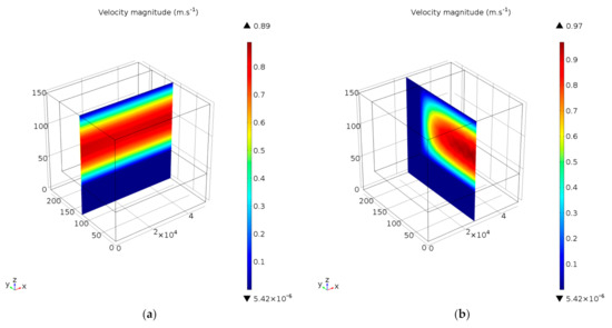
Figure 8.
Velocity profiles in (a) axial, and (b) cross-sectional microchannel planes (axes in µm). Reaction conditions: temperature 120 °C and space velocity 65.2 NL gcat−1 h−1.
Reaction Rate Profiles
In Figure 9, the reaction rates of CO oxidation (Figure 9a), H2 oxidation (Figure 9b), and the reversible WGS (Figure 9c) are illustrated against the normalised microchannel length (x/L) at different reaction temperatures and a space velocity of 65.2 NL gcat−1 h−1. Due to the Arrhenius effect, the reaction rate magnitudes for all three reactions increased with temperature at the microchannel inlet (x/L = 0). In particular, initial CO and H2 oxidation rates exhibited magnitudes of 2740 and 130 mol m−3 s−1, respectively, at the microchannel inlet and for the 200 °C temperature condition.
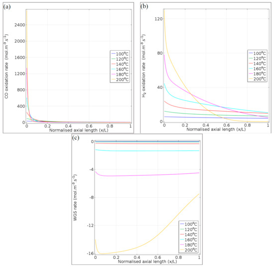
Figure 9.
Reaction rate profiles of (a) CO oxidation, (b) H2 oxidation, and (c) reversible WGS, along the normalised axial length of the microchannel. Reaction conditions: temperatures 100–200 °C and space velocity 65.2 NL gcat−1 h−1.
In the case of the WGS reaction, the reaction rates were negative, indicating that the RWGS reaction dominates. In Figure 9a, the sharp decrease in the CO oxidation rate in the first tenth of the reactor length is attributed to the rapid depletion of CO and O2 in the gas mixture. In general, this was observed for CO oxidation over the entire temperature range (100–200 °C). The decline in the rate of H2 oxidation further along the microchannel length (Figure 9b) is due to O2 consumption because the kinetic rate expression (Equation (7)) only depends on the concentration of O2 (limiting reactant in Equation (2)). The effects of the RWGS were more significant at temperatures of 180 and 200 °C. At 200 °C, the RWGS reaction rate reaches a maximum of ~16 mol m−3 s−1 due to CO consumption via oxidation in the first tenth of the microchannel (RWGS producing CO to compensate for CO conversion by oxidation). Thereafter, the effect of the RWGS reaction becomes milder as more CO is formed through RWGS and less CO2 is produced due to the depletion of O2 in the second half of the microchannel (x/L = 0.4–1).
The total rate of reaction of CO, via both the oxidation and the reversible WGS reactions, is illustrated for 100°C in Figure 10a and for 200°C in Figure 10b, at a space velocity of 65.2 NL gcat−1 h−1. It is observed that at a lower temperature (100°C), the consumption of CO via its oxidation dominates in the entire microchannel length (positive magnitude of reaction rate), while at 200°C, some RWGS was noticed (slight negative rates towards the microchannel outlet). These observations correspond to those in Figure 9a,b. A calculation (<0.1) of the Damköhler number revealed that internal diffusion did not play a role in limiting the CO oxidation reaction; the reaction was kinetically limited throughout the length of the microchannel, even at 200°C. From these reaction rate profiles, the optimum temperature ranges for CO PROX can be selected. A trade-off between maximising the CO oxidation rate and minimising both the rates of H2 oxidation and the RWGS is evident; for instance, at 65.2 NL gcat−1 h−1, the CO conversion could be near equilibrium in the temperature range 120–160 °C, while the H2 oxidation and RWGS reaction rates are relatively low.
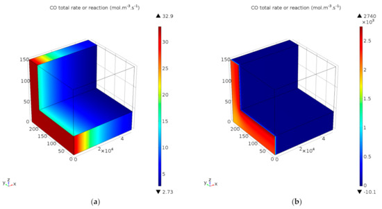
Figure 10.
Total rate of reaction of CO, incorporating oxidation and reversible WGS, for reaction temperatures of (a) 100 °C and (b) 200 °C. Space velocity corresponds to 65.2 NL gcat−1 h−1.
Concentration Profiles
The consumption and formation of CO, respectively, via oxidation and RWGS, are presented in Figure 11a for 65.2 NL gcat−1 h−1 and in Figure 11b for 130.4 NL gcat−1 h−1, illustrating its molar concentration at different reaction temperatures along the axial length (x/L) of the microchannel. For all the reaction temperatures and at 65.2 NL gcat−1 h−1 (Figure 11a), CO consumption due to oxidation (hence a reduction in its molar concentration) takes place in the axial location x/L = 0–0.1 of the microchannel. A similar observation was made for the CO oxidation rate in Figure 9a. Although the experiments indicated very high CO conversion at 120 °C, the CFD model predicts some CO in the product gas (0.03 mol m−3). Furthermore, for the 65.2 NL gcat−1 h−1 space velocity condition, at reaction temperatures of 140 and 160 °C, it was observed that the almost complete reaction of CO takes place (CO product molar concentration ~0 mol m−3 at x/L = 1). On the other hand, at 200 °C (as was observed in the product gas during the experimental investigation), the effect of the RWGS reaction is clear in the microchannel’s axial distance (x/L = 0.3–1); CO formation takes place and its concentration increases to 0.28 mol m−3 at the microchannel outlet (x/L = 1).
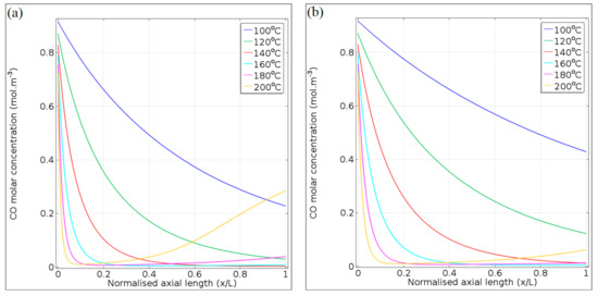
Figure 11.
CO concentration profiles for (a) 65.2 NL gcat−1 h−1 and (b) 130.4 NL gcat−1 h−1, at 100–200 °C.
Due to the reduced residence time when a space velocity of 130.4 NL gcat−1 h−1 is applied, the range of feasible reaction temperatures that provide high CO conversion shifts to a higher temperature range. This was also observed in the experimental investigation. At this space velocity, a reaction temperature of 160 °C provides the best CO conversion and CO product molar concentration (Figure 11b). At 200 °C, the effect of the RWGS reaction that produces CO at axial position x/L = 0.4–1 is not as strong as in the case of 65.2 NL gcat−1 h−1 (Figure 11a). However, it should be noted that the model over-predicted the CO conversion in Figure 7d by 15.5%, which means that the experimental CO product molar concentration (x/L = 1) could be ~0.07 mol m−3, instead of the 0.06 mol m−3 as predicted in Figure 11b.
In Figure 12, the molar concentration profiles are presented exclusively for the 65.2 NL gcat−1 h−1 space velocity, for the gaseous species of CO2, H2, O2, and H2O in Figure 12a, 10b, 10c, and 10d, respectively. As in Figure 11, the species concentrations are presented for the temperature range 100–200 °C, and plotted against the axial length of the microchannel (x/L). It is important that the molar concentration of each gas species is affected by the gas density in the microchannel (temperature effect). In general, the gas species contained within the feed gas (CO2, H2, and O2) showed their highest initial concentrations (x/L = 0) at the lowest reaction temperature (100 °C). However, the molar concentration gradients along the microchannel length (x/L = 0–1) are caused by species consumption and formation via the PROX reactions (Equations (1)–(3)).
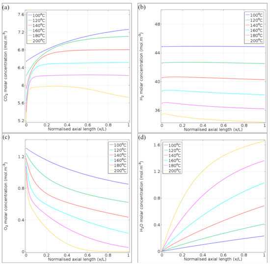
Figure 12.
Concentration profiles of (a) CO2, (b) H2, (c) O2, and (d) H2O, at 65.2 NL gcat−1 h−1 and 100–200 °C.
The concentration of CO2 (Figure 12a) increased steadily at 100 °C as a result of its formation through the CO oxidation reaction. However, the CO oxidation reaction is sluggish at this temperature and CO consumption was observed to be incomplete at the microchannel outlet (Figure 11a). The plateau in the CO2 concentrations observed for the temperature range 120–180 °C is due to the decrease in the CO oxidation rates (Figure 9a), resulting from CO depletion from the gas mixture (Figure 11a). At 200 °C, the effect of the RWGS reaction is evident at x/L = 0.5–1, as CO2 is consumed by this side reaction. From the CO2 concentration’s plateau (~6 mol m−3), its concentration ultimately decreased to 5.72 mol m−3 at the microchannel outlet.
The nearly constant H2 concentrations at 100–140 °C (Figure 12b) confirmed that the H2 oxidation and RWGS reactions could be limited by operating the microchannel reactor at lower reaction temperatures. At reaction temperatures >160 °C, greater H2 loss via oxidation, and RWGS takes place. This was evident in the magnitude of the reaction rates of H2 oxidation (Figure 9b) and RWGS (Figure 9c).
The O2 molar concentration is typically temperature-dependent (higher temperatures showing stronger kinetic and O2 consumption effects), and its concentration decreases exponentially with the microchannel length (Figure 12c). At axial locations x/L = 0.05–0.1, slight deviations in the O2 concentration profiles (flexi points) for the temperatures 140–200 °C are observed, as a result of the depletion of CO during oxidation. Further consumption of O2 (x/L = 0.3–1) is almost exclusively due to the H2 oxidation reaction in this temperature range. Due to the fast depletion rate of O2 at 200 °C (not being able to significantly contribute to the CO conversion, especially at axial location x/L = 0.5–1), the RWGS reaction exhibits significant CO production at this temperature and in the latter part of the microchannel (Figure 11a).
The increase in the H2O molar concentration is dominated by the H2 oxidation reaction, although only to a mild extent at temperatures in the range 100–140 °C (Figure 12d). At 180 °C, H2O production is a result of a combination of H2 oxidation and RWGS. This is because the O2 is not completely depleted at the outlet of the microchannel reactor (x/L = 1, Figure 12c). At 200 °C, O2 depletion explains the slight decrease in the slope of the H2O concentration profile in the second half of the microchannel length (x/L = 0.5–1).
5. Conclusions
CO poisoning is a real issue when it comes to fossil-derived hydrogen for low-temperature electrochemical processes, especially power generation using PEMFC. CO PROX is a well-known industrial process for the removal of CO from gas mixtures. For small-scale applications, microchannel reactors (with enhanced mass transfer, near isothermal operation, and high throughput characteristics) offer a compact catalytic reactor technology suitable for CO PROX. In this paper, a microchannel reactor coated with a Ru-Cs/Al2O3 catalyst demonstrated the reduction of CO at an initial concentration of 1.4 vol.% in a H2-rich gas mixture to ppm levels as low as 42 ppm at reaction temperatures of 120–140 °C and at space velocities of 65.2 and 97.8 NL gcat−1 h−1. A CO selectivity of 50.3% was achieved at 120 °C and a space velocity of 65.2 NL gcat−1 h−1—this corresponds to a H2 energy loss of only 2%. Despite this promising reactor behaviour in the range of reaction temperatures (100–200 °C) and space velocities (32.6–130.4 NL gcat−1 h−1) investigated, we did observe that non-optimal reaction conditions may lead to substandard CO conversion (<95%) and increased H2 loss (~6.5%) due to secondary catalytic reactions, i.e., H2 oxidation and RWGS. From a practical perspective, it is also recommended that future work and upscaling of the CO PROX process investigates Ru catalyst loadings less than 8.5 wt.% Ru to limit costs.
Identifying and understanding reactor operating regimes was, therefore, important to describe microchannel reactor performance for high CO conversion, selectivity, and throughput. Here, a CFD model was developed to validate experimental results and understand reaction-coupled mass transport within the microchannel reactor. Kinetic rate expressions were adapted from the literature using a method that combined manual parameter estimation and parameter regression. Indications with the bootstrap statistical method were that the model described the experimental data to a level of confidence far greater than 95%. Species transport within the microchannel reactor’s axial length provided a critical analysis of the reaction dynamics of the CO PROX system involving CO oxidation, H2 oxidation, and RWGS reactions. It is envisaged that, in future, the CFD model could guide innovation for the upscaling of microchannel reactors for CO PROX—to assist in the identification of suitable operating regimes, while limiting H2 consumption via its oxidation and the undesirable effects of the RWGS reaction.
Author Contributions
Conceptualisation, N.E., R.C.E., and D.B.; data curation, K.C.M.; formal analysis, K.C.M. and N.E.; funding acquisition, D.B.; investigation, K.C.M.; methodology, K.C.M.; project administration, K.C.M. and N.E.; resources, N.E. and D.B.; software, K.C.M. and G.L.G.; supervision, N.E., R.C.E., and D.B.; validation, K.C.M. and G.L.G.; visualisation, K.C.M.; writing—original draft, K.C.M.; writing—review and editing, N.E., R.C.E., and G.L.G. All authors have read and agreed to the published version of the manuscript.
Funding
This research was funded by the Department of Science and Innovation (DSI), HySA Infrastructure Centre of Competence in South Africa [KP5 program].
Institutional Review Board Statement
Not applicable.
Informed Consent Statement
Not applicable.
Data Availability Statement
Not applicable.
Acknowledgments
The authors express their gratitude to Andrei Kolesnikov (Tshwane University of Technology, South Africa) for his assistance concerning CFD modelling and optimisation.
Conflicts of Interest
The authors declare no conflict of interest.
Nomenclature
The following abbreviations are used in this manuscript:
| CFD | Computational fluid dynamic |
| CO PROX | Preferential oxidation of CO |
| OD | Outside diameter |
| PEMFC | Proton exchange membrane fuel cell |
| RWGS | Reverse water–gas shift |
| vol.% | Volume percent |
| WGS | Water–gas shift |
| wt.% | Weight percent |
The following symbols are used in this manuscript:
| a, b, c | Orders of reaction |
| CF | Forchheimer drag coefficient |
| Ci | Molar concentration of species i in the mixture, mol m−3 |
| Cp | Specific heat capacity, J kg−1 K−1 |
| DH | Microchannel hydraulic diameter, m |
| Deff | Effective binary diffusion coefficient, m2 s−1 |
| Dij | Binary diffusion coefficient of species i in species j, m2 s−1 |
| Dij eff | Effective binary diffusion coefficient of species i in species j, m2 s−1 |
| e | Residuals between calculated experimental CO conversions |
| E | Activation energy, J mol−1 |
| Fi | Volumetric flow rate of species i, m3 s−1 |
| gcat | Gram of catalyst |
| k | Thermal conductivity, W m−1 K−1 |
| Keq | Equilibrium constant |
| ki | Reaction rate pre-exponential constant of reaction i |
| Ki | Adsorption constant of component i, m3 mol−1 |
| M | Mean molar mass, kg mol−1 |
| Mi | Molar mass of species i, kg mol−1 |
| n | Vector normal to the symmetry plane |
| Ni | Number of moles of species i |
| P | Pressure, Pa |
| Patm | Atmospheric pressure, Pa |
| Pi | Partial pressure of species i, Pa |
| R | Universal gas constant, Pa m3 mol−1 K−1 |
| r | Rate of reaction, mol m−3 s−1 |
| Rr | Rate of reaction, mol kg−1 s−1 |
| SCO | CO selectivity, % |
| T | Temperature, K |
| T0 | Reference temperature, K |
| u | Linear velocity, m s−1 |
| XCO | CO conversion, % |
| Xg,h | CO conversions at temperature g and flow rate h |
| ΔH | Enthalpy of reaction, J mol−1 |
| ΔHi | Adsorption enthalpy of species i, J mol−1 |
| ΔHr | Heat of reaction, J mol−1 |
The following Greek symbols are used in this manuscript:
| α | Significance level, used in the F-test |
| β0 | Average of simulated CO conversions |
| δ | Porous washcoat thickness, m |
| ε | Porosity of the catalyst |
| κ | Permeability of the catalyst, m2 |
| ρ | Gas density, kg m−3 |
| ρs | Solid catalyst density, kg m−3 |
| θ | Parameters used during optimisation |
| μ | Viscosity, Pa.s |
| υi | Atomic volume of species i, cm3 mol−1 |
| ωi | Weight fraction of species i, cm3 mol−1 |
The following subscripts are used in this manuscript:
| eff | Effective |
| g | Number of temperatures used in the model (1, …, 6) |
| h | Number of flow rates used in the model (1, …, 4) |
| i, j | Component i or j |
| in | Reactor inlet |
| out | Reactor outlet |
| s | Solid |
| wall | Reactor wall |
Appendix A. Governing Equations Describing the Microchannel Reactor within the CFD Model

Table A1.
Summary of CFD model governing equations. Adapted with permission from S. Chiuta, R.C. Everson, H.W.J.P. Neomagus, L.A. Le Grange, D.G. Bessarabov, International Journal of Hydrogen Energy; published by Elsevier, 2014 [21].
Table A1.
Summary of CFD model governing equations. Adapted with permission from S. Chiuta, R.C. Everson, H.W.J.P. Neomagus, L.A. Le Grange, D.G. Bessarabov, International Journal of Hydrogen Energy; published by Elsevier, 2014 [21].
| Governing Equation | Formula |
|---|---|
| Ideal gas law | |
| Fuller–Schettler–Giddings equation | |
| Free-fluid region | |
| Continuity equation | |
| Navier–Stokes momentum equation | |
| Species continuity equation | |
| Energy equation | |
| Porous catalyst layer | |
| Continuity equation | |
| Brinkman–Forchheimer–Darcy equation | |
| Species continuity equation | |
| Bruggeman correlation | |
| Energy equation | |

Table A2.
Summary of CFD model boundary conditions [21]. Adapted with permission from S. Chiuta, R.C. Everson, H.W.J.P. Neomagus, L.A. Le Grange, D.G. Bessarabov, International Journal of Hydrogen Energy; published by Elsevier, 2014.
Table A2.
Summary of CFD model boundary conditions [21]. Adapted with permission from S. Chiuta, R.C. Everson, H.W.J.P. Neomagus, L.A. Le Grange, D.G. Bessarabov, International Journal of Hydrogen Energy; published by Elsevier, 2014.
| Condition | Formula |
|---|---|
| No slip condition at the wall | |
| Average inlet gas velocity | |
| Outlet pressure | |
| Symmetry plane | |
| Inlet mass fraction |
Appendix B. Goodness of Fit Using the Bootstrap Statistical Method
The differences between the experimental and modelled CO conversions (Figure A1) are not normally distributed, do not have a constant variance, and are temperature-dependent. These facts, in addition to the small sample size and the non-linearity of the model, prevented the application of the F-test. The bootstrap method was subsequently applied in this case.
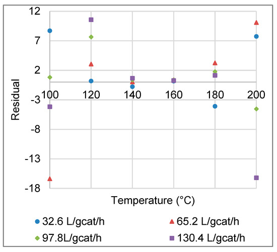
Figure A1.
Residuals between experimental and modelled CO conversions, as a function of reaction temperature (Data are combined for the four space velocities investigated).
Suppose the relationship between CO conversions (X), temperatures (T) and space velocities (F) can be described by:
where g = 1, …, 6; h = 1, …, 4 and = [EC, ED, kC, kD], are random variables from some unknown distribution.
Under the null hypothesis, the covariates (T and F) have no effect on , and, therefore, we can state the null hypothesis as:
Note that if is true, then we have a linear model, which enables us to generate the null distribution using methods developed for linear models [35,36], where the null distribution is the distribution of under . To simulate the null distribution, the observed residuals under are equal to the centred observations . A bootstrap sample of size B is generated from these observations by taking the possible dependencies in the observed sample into account. In other words, B samples are sampled using the wild bootstrap proposed by Wu [35] and Liu [36]. For each bootstrap sample, the sum of the squared residuals (SSR) are calculated by . To apply the test, the observed residuals obtained from fitting the modelled CO conversions to experimental data (Equation B1) are used to calculate the observed SSR, given by . A decision can then be made to either reject the null hypothesis or accept it, by comparing with the range of values of obtained from our B bootstrap samples—if is less than the percentile of then the null hypothesis is rejected.
References
- Du, X.; Lang, Y.; Cao, K.; Yang, J.; Cai, J.; Shan, B.; Chen, R. Bifunctionally faceted Pt/Ru nanoparticles for preferential oxidation of CO in H2. J. Catal. 2021, 396, 148–156. [Google Scholar] [CrossRef]
- Qiu, Z.; Guo, X.; Mao, J.; Zhou, R. The catalytic performance of isolated-dispersed Au on nanosized CeO2 for CO preferential oxidation in H2-rich stream. Appl. Surf. Sci. 2019, 481, 1072–1079. [Google Scholar] [CrossRef]
- Fiorenza, R.; Spitaleri, L.; Gulino, A. Ru–Pd Bimetallic catalysts supported on purification through CO preferential oxidation. Catalysts 2018, 8, 203. [Google Scholar] [CrossRef]
- Galletti, C.; Specchia, S.; Saracco, G.; Specchia, V. CO preferential oxidation in H2-rich gas for fuel cell applications: Microchannel reactor performance with Rh-based catalyst. Int. J. Hydrogen Energy 2008, 33, 3045–3048. [Google Scholar] [CrossRef]
- Mohaideen, K.K.; Kim, W.; Koo, K.Y.; Yoon, W.L. Highly dispersed Ni particles on Ru/NiAl catalyst derived from layered double hydroxide for selective CO methanation. Catal. Commun. 2015, 60, 8–13. [Google Scholar] [CrossRef]
- Nunez, N.E.; Bideberripe, H.P.; Mizrahi, M.; Ramallo-Lopez, J.M.; Casella, M.L.; Siri, G.J. CO selective oxidation using Co-promoted Pt-Al2O3 catalysts. Int. J. Hydrogen Energy 2016, 41, 19005–19013. [Google Scholar] [CrossRef]
- Arzamendi, G.; Uriz, I.; Diéguez, P.M.; Laguna, O.H.; Hernández, W.Y.; Álvarez, A.; Centeno, M.A.; Odriozola, J.A.; Montes, M.; Gandía, L.M. Selective CO removal over Au/CeFe and CeCu catalysts in microreactors studied through kinetic analysis and CFD simulations. Chem. Eng. J. 2011, 167, 588–596. [Google Scholar] [CrossRef]
- Grisel, R.J.H.; Nieuwenhuys, B.E. Selective oxidation of CO, over supported Au catalysts. J. Catal. 2001, 199, 48–59. [Google Scholar] [CrossRef]
- Zou, X.; Qi, S.; Suo, Z.; An, L.; Li, F. Activity and deactivation of Au/Al2O3 catalyst for low-temperature CO oxidation. Catal. Commun. 2007, 8, 784–788. [Google Scholar] [CrossRef]
- Miao, Y.X.; Shi, L.; Sun, Q.; Li, W.C. A highly efficient potassium-treated Au-Cu/Al2O3 catalyst for the preferential oxidation of carbon monoxide. RSC Adv. 2016, 6, 24603–24609. [Google Scholar] [CrossRef]
- Beck, A.; Yang, A.; Leland, A.R.; Riscoe, A.R.; Lopez, F.A.; Goodman, E.D.; Cargnello, M. Understanding the preferential oxidation of carbon monoxide (PROX) using size-controlled Au nanocrystal catalyst. Am. Inst. Chem. Eng. 2018, 64, 3159–3167. [Google Scholar] [CrossRef]
- Bion, N.; Epron, F.; Moreno, M.; Mariño, F.; Duprez, D. Preferential oxidation of carbon monoxide in the presence of hydrogen (PROX) over noble metals and transition metal oxides: Advantages and drawbacks. Top. Catal. 2008, 51, 76–88. [Google Scholar] [CrossRef]
- Wang, C.; Cheng, Q.; Wang, X.; Ma, K.; Bai, X.; Tan, S.; Tian, Y.; Ding, T.; Zheng, L.; Zhang, J.; et al. Applied surface science enhanced catalytic performance for CO preferential oxidation over CuO catalysts supported on highly defective CeO2 nanocrystals. Appl. Surf. Sci. 2017, 422, 932–943. [Google Scholar] [CrossRef]
- Han, Y.F.; Kahlich, M.J.; Kinne, M.; Behm, R.J. Kinetic study of selective CO oxidation in H2-rich gas on a Ru/γ-Al2O3 catalyst. Phys. Chem. Chem. Phys. 2002, 4, 389–397. [Google Scholar] [CrossRef]
- Xu, G.; Zhang, Z.G. Preferential CO oxidation on Ru/Al2O3 catalyst: An investigation by considering the simultaneously involved methanation. J. Power Sources 2006, 157, 64–77. [Google Scholar] [CrossRef]
- Kim, Y.H.; Park, E.D. The effect of the crystalline phase of alumina on the selective CO oxidation in a hydrogen-rich stream over Ru/Al2O3. Appl. Catal. B Environ. 2010, 96, 41–50. [Google Scholar] [CrossRef]
- Gokhale, S.V.; Tayal, R.K.; Jayaraman, V.K.; Kulkarni, B.D. Microchannel reactors: Applications and use in process development. Int. J. Chem. React. Eng. 2005, 3, 1–53. [Google Scholar] [CrossRef]
- Snytnikov, P.V.; Potemkin, D.I.; Rebrov, E.V.; Sobyanin, V.A.; Hessel, V.; Schouten, J.C. Design, scale-out, and operation of a microchannel reactor with a Cu/CeO2-x catalytic coating for preferential CO oxidation. Chem. Eng. J. 2010, 160, 923–929. [Google Scholar] [CrossRef]
- Uriz, I.; Arzamendi, G.; Diéguez, P.M.; Laguna, O.H.; Centeno, M.A.; Odriozola, J.A.; Gandía, L.M. Preferential oxidation of CO over Au/CuOx-CeO2 catalyst in microstructured reactors studied through CFD simulations. Catal. Today 2013, 216, 283–291. [Google Scholar] [CrossRef]
- Laguna, O.H.; Ngassa, E.M.; Oraá, S.; Álvarez, A.; Domínguez, M.I.; Romero-Sarria, F.; Arzamendi, G.; Gandía, L.M.; Centeno, M.A.; Odriozola, J.A. Preferential oxidation of CO (CO-PROX) over CuOx/CeO2 coated microchannel reactor. Catal. Today 2012, 180, 105–110. [Google Scholar] [CrossRef]
- Chiuta, S.; Everson, R.C.; Neomagus, H.W.J.P.; Le Grange, L.A.; Bessarabov, D.G. A modelling evaluation of an ammonia-fuelled microchannel reformer for hydrogen generation. Int. J. Hydrogen Energy 2014, 39, 11390–11402. [Google Scholar] [CrossRef]
- O’Connell, M.; Kolb, G.; Schelhaas, K.P.; Wichert, M.; Tiemann, D.; Pennemann, H.; Zapf, R. Towards mass production of microstructured fuel processors for application in future distributed energy generation systems: A review of recent progress at IMM. Chem. Eng. Res. Des. 2012, 90, 11–18. [Google Scholar] [CrossRef]
- Engelbrecht, N.; Chiuta, S.; Everson, R.C.; Neomagus, H.W.J.P.; Bessarabov, D.G. Experimentation and CFD modelling of a microchannel reactor for carbon dioxide methanation. Chem. Eng. J. 2017, 313, 847–857. [Google Scholar] [CrossRef]
- Chiuta, S.; Everson, R.C.; Neomagus, H.W.J.P.; Bessarabov, D.G. Performance evaluation of a high-throughput microchannel reactor for ammonia decomposition over a commercial Ru-based catalyst. Int. J. Hydrogen Energy 2015, 40, 2921–2926. [Google Scholar] [CrossRef]
- COMSOL. Chemical Reaction Engineering Module User’s Guide. Available online: https://doc.comsol.com/5.4/doc/com.comsol.help.chem/ChemicalReactionEngineeringModuleUsersGuide.pdf (accessed on 5 May 2021).
- CHERIC. Korean Thermophysical Properties Database. Available online: www.cheric.org (accessed on 4 March 2020).
- Fuller, E.N.; Schettler, P.D.; Giddings, J.C. A new method for prediction of binary gas-phase diffusion coefficients. Ind. Eng. Chem. 1966, 58, 18–27. [Google Scholar] [CrossRef]
- Baughman, A.C.; Huang, X.; Martin, L.L. Evaluating kinetic models for preferential CO-oxidation catalysts using optimization-based parameter estimation. J. Power Sources 2012, 210, 402–408. [Google Scholar] [CrossRef]
- Garbis, P.; Kern, C.; Jess, A. Kinetics and reactor design aspects of selective methanation of CO over a Ru/γ-Al2O3 catalyst in CO2/H2 rich gases. Energies 2019, 12, 469. [Google Scholar] [CrossRef]
- Froment, G.; Bischoff, K.; De Wilde, J. Chemical Reactor Analysis and Design, 3rd ed.; John Wiley and Sons: Hoboken, NJ, USA, 2011. [Google Scholar]
- Ramanathan, K.; Sharma, C.S. Kinetic parameters estimation for three way catalyst modeling. Ind. Eng. Chem. Res. 2011, 50, 9960–9979. [Google Scholar] [CrossRef]
- Spiess, A.-N.; Neumeyer, N. An evaluation of R2 as an inadequate measure for nonlinear models in pharmacological and biochemical research: A Monte Carlo approach. BMC Pharmacol. 2010, 10, 6. [Google Scholar] [CrossRef]
- Wehrens, R.; van der Linden, W.E. Bootstrapping principal component regression models. J. Chemom. 1997, 11, 157–171. [Google Scholar] [CrossRef]
- Wehrens, R.; Putter, H.; Buydens, L.M.C. The bootstrap: A tutorial. Chemom. Intell. Lab. Syst. 2000, 54, 35–52. [Google Scholar] [CrossRef]
- Wu, C. Jackknife, Bootstrap and other resampling methods in regression analysis. Ann. Stat. 1986, 14, 1261–1295. [Google Scholar] [CrossRef]
- Liu, R.Y. Bootstrap procedures under some non-I.I.D. Models. Ann. Stat. 1988, 16, 1696–1708. [Google Scholar] [CrossRef]
Publisher’s Note: MDPI stays neutral with regard to jurisdictional claims in published maps and institutional affiliations. |
© 2021 by the authors. Licensee MDPI, Basel, Switzerland. This article is an open access article distributed under the terms and conditions of the Creative Commons Attribution (CC BY) license (https://creativecommons.org/licenses/by/4.0/).