Article

Flow and Heat Transfer Property of Oldroyd-B-Fluid-Based Nanofluids Containing Cylindrical Particles in a Pipe

1
School of Media and Design, Hangzhou Dianzi University, Hangzhou 310018, China
2
State Key Laboratory of Fluid Power Transmission and Control, Zhejiang University, Hangzhou 310027, China
*
Author to whom correspondence should be addressed.
Processes 2021, 9(4), 647; https://doi.org/10.3390/pr9040647
Submission received: 18 March 2021 / Revised: 2 April 2021 / Accepted: 2 April 2021 / Published: 8 April 2021
(This article belongs to the Special Issue Enhancement of Heat Transfer and Fluid Flow)

Abstract

:
Flow and heat transfer property of Oldroyd-B-fluid-based nanofluids containing cylindrical particles are studied in a pipe with circular cross-section in the range of Reynolds number (Re) from 100 to 2000, Weissenberg number (We) from 0.1 to 2, particle aspect ratio (β) from 2 to 16 and particle volume concentration (Φ) from 0.1% to 2.5%. The motion equation of Oldroyd-B fluid with particles, the equation for probability density function of particle orientation and convection-diffusion equation for particles are solved numerically. The numerical method used in the simulation is validated by comparing with the available results. The effects of Re, We, β and Φ on the friction factor (f), Nusselt number (Nu) and ratio of energy performance evaluation criterion (PECt/PECf) for Oldroyd-B-fluid-based nanofluids to that for Oldroyd-B fluids are discussed. The results showed that the values of f and Nu of Oldroyd-B-fluid-based nanofluids are larger than that of water-based nanofluids and that of pure Oldroyd-B fluids. The values of f increase with increasing Re, We and Φ, but with decreasing β. The values of Nu and PECt/PECf are enhanced with increasing Re, We, β and Φ. The increase of f is larger than that of Nu at lower Re, but is less than that of Nu at higher Re. It is more effective to use Oldroyd-B-fluid-based nanofluids with cylindrical nanoparticles to improve the heat transfer at the conditions of higher Re, We, β and Φ. Finally, the correlation formula of PECt/PECf as a function of Re, We, β and Φ is derived.

1. Introduction

Mechanical and heat transfer characteristics of non-Newtonian fluids are of great interest due to its wide engineering applications, for example, polymer extrusion, glass manufacturing, tailings, paper-making [1,2]. In order to improve the flow and heat transfer of the base fluids, nanoparticles are immersed into the base fluids, i.e., nanofluids. So far a growing number of attentions have been paid to the potentials of nanofluids in the applications [3]. Most of these studies use Newtonian fluids as the base fluids, and many valuable conclusions are obtained. For example, nanoscale additives could to reduce friction in [4]. Using water–CuO causes 13.8, 1.5 and 1.3% higher thermal efficiency in comparison with employing pure water, water–TiO2 and water–Al2O3 nanofluids, respectively, in a U-shaped solar tube collector [5]. Water-Al2O3 and -SiO2 nanofluids had the best effect for the flow and heat transfer in a spiral double-pipe heat exchanger with the Reynolds numbers of 10,551~17,220 and 17,220~31,910, respectively [6].
There are also some studies with non-Newtonian fluids as base fluids. Sandeep et al. [7] found that nanoparticles enhanced the thermal conductivity of Jeffrey nanofluids comparing with the Oldroyd-B nanofluids in the electrically conducting liquid film flow dispensed with grapheme particle, and Deborah number played a major role in convective heat transfer. Sulaiman et al. [8] showed that the fluid relaxation and retardation time parameter would have opposite impacts on the fluid velocity in a flow of Oldroyd-B nanofluids over a surface. Sandeep et al. [9] indicated that the Oldroyd-B nanofluids had worse heat transfer performance than the Jeffrey nanofluids when thermal radiation, transverse magnetic field, suction effects and non-uniform heat source/sink were considered. Aziz et al. [10] found that the heat transfer rate was significantly enhanced in the flow of Oldroyd-B liquid with nanoparticles suspended at higher Biot and Prandtl numbers.
As is shown above, the studies were focused on the nanofluids with spherical particles. However, the flow and heat transfer property of nanofluids are sensitive to particle shape. Among the non-spherical particles the cylindrical particle is the most common particle. It is more difficult to deal with the cylindrical particles because particle rotation and its orientation are strongly coupled with the translation motion, which affects the pressure drop and heat transfer property. Some valuable findings have been obtained for nanofluids with cylindrical particles and Newtonian fluids as the base fluids. For example, the cylindrical SiC particles had a higher thermal conductivity than the spherical particles [11]. Ahmed et al. [12] studied the viscous nanofluid flow over a curved stretching surface with single-walled carbon nanotubes as a solid constituent of the nanofluids. Thermal conductivity was significantly enhanced even at low concentration of carbon nanotubes [13]. Adding the nanofluids with 5% volume concentration of TiO2 nanorods led to an increase of thermal conductivity 33% over the water, and the increase of thermal conductivity was proportional to the particle concentration [14]. The increase of thermal conductivity was resulted from the percolation of heat through the nanotube in the nanofluids with carbon nanotube [15]. Adding cylindrical particles would produce better effect of improving heat transfer showed higher entropy generation than the particles with other shapes [16]. Cylindrical particle colliding with heat source led to a more significant increase in heat transfer than spherical particle [17]. The increase of heat transfer was proportional to the concentration and aspect ratio of cylindrical particles in a laminar pipe flow, and friction factor decreased with increasing the Reynolds number [18].
However, there were little researches on the flow and heat transfer of non-Newtonian-fluid- based nanofluids with cylindrical particles. Among them, the most commonly used base fluid is polyalphaolefins which is lubricant and coolant in various applications and has the characteristics of shear thinning. Shaikh et al. [19] found that the polyalphaolefins-based nanofluids containing carbon tubes showed the best effect in improving thermal conductivity, followed by exfoliated graphite and heat treated nanofibers. Nelson et al. [20] indicated that the precipitation of particles on the wall led to the enhancement of heat transfer in Polyalphaolefins-based nanofluids with the exfoliated graphite fibers. Yu et al. [21] showed that the thermophysical properties of polyalphaolefins-based nanofluids synthesized with Al2O3 rod-like nanoparticles were dependent on the particle concentration and aspect ratio, aggregation and dispersion.
The literature survey reveals that there is a lack of study on the flow and heat transfer of Oldroyd-B-fluid-based nanofluids with cylindrical particles. The Oldroyd-B fluid, as one kind of non-Newtonian fluids, possesses the properties of both the relaxation time and the retardation time, can describes many actual flowing medium and hence attracts wide interest. Different from the Polyalphaolefins, the Oldroyd-B fluid shows its specific rheological property. Comparing with the pure Oldroyd-B fluid and water-based nanofluids, how does immersing particles into Oldroyd-B fluid change the flow and heat transfer property? Comparing with the spherical particles, how do the cylindrical nanoparticles affect the flow and heat transfer behavior? In this work, therefore, a numerical simulation is performed to explore the effects of the Reynolds number, Weissenberg number, and particle aspect ratio and concentration on the friction factor and heat transfer property of Oldroyd-B-fluid-based Al2O3 nanofluids with cylindrical nanoparticles in a pipe flow.

2. Governing Equations

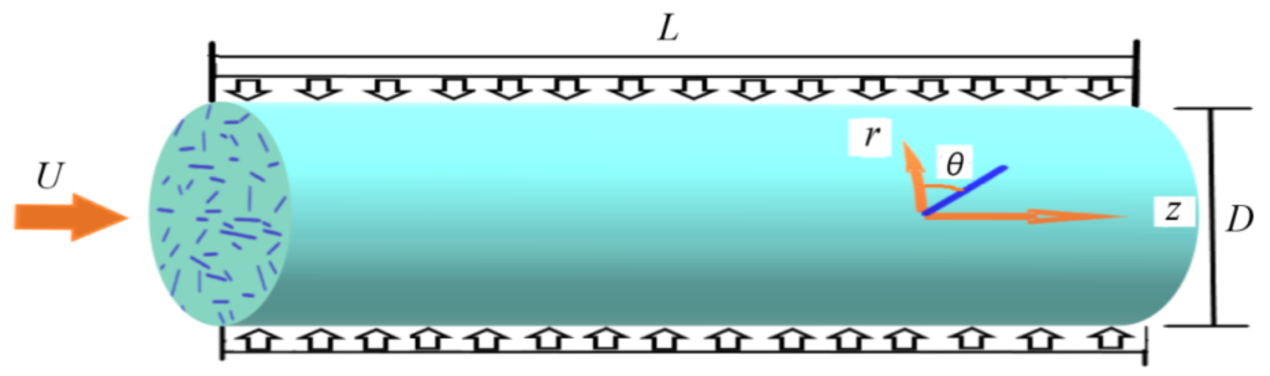
2.1. Equations of Oldroyd-B-Fluid Flow Containing Cylindrical Particles

Oldroyd-B-fluid- based nanofluids with cylindrical particles flow from left to right through a pipe with diameter D and length L as shown in Figure 1. Here a cylindrical coordinate system is used. The wall of the pipe is assumed to be smooth. No-slip boundary condition for the nanofluids is applied to the wall. Oldroyd-B fluid, as a kind of viscoelastic fluid, is equivalent to a fluid filled with elastic bead and spring dumbbells. For the incompressible flow, the continuity and momentum equations of Oldroyd-B fluid flow containing cylindrical particles are [22]:
Figure 1. Schematic diagram of Oldroyd-B fluid flow containing cylindrical particles and coordinate system.
Processes 09 00647 g001
u = 0
u t + u u = p + 2 u Re + μ b Re τ + μ a Re [ ( a 4 1 3 I a 2 ) : ε ] .
The last term on the right-hand side of Equation (2) is the contribution from the cylindrical particles. In Equation (2), u and p are the nanofluid velocity and pressure, respectively; μb is the ratio of the total viscosity to the solvent viscosity in the Oldroyd-B fluid; a2 and a4 are the second- and fourth-order tensors of particle orientation, respectively; ε is the rate-of-strain tensor; I is the unit tensor; apparent viscosity coefficient μa is a function of particle concentration and aspect ratio, and can be given by extending Batchelor’s theory [23]:
μ a = 2 3 Φ β 2 { 1 ln 2 β [ ln 2 β + 0.64 ln 2 β 1.5 + 1.659 ( ln 2 β ) 2 ] + 0.606 Φ β 2 2 π 1 ( ln 2 β ) 3 } ,
where Φ is the particle volume fraction; β is the particle aspect ratio. Working ranges of Equation (3) are β ≤ 51 and Φ ≤ 1%. In Equation (2) τ is the viscoelastic stress tensor, and related constitutive equation for the Oldroyd-B fluid is:
We τ + τ = ε ,
where the Weissenberg number (We = λU/D, λ is the fluid relaxation time) is defined as the ratio of the characteristic fluid relaxation time to the characteristic time scale in the flow; symbol (∇) is the upper-convected time derivative:
τ τ t + u τ ( u ) T τ τ u .
In Equation (2) Re = ρtUD/μt is the Reynolds number, where U and D are the characteristic velocity and length, ρt and μt are the nanofluid density and viscosity, respectively. The nanofluid density is:
ρ t = ( 1 Φ ) ρ f + Φ ρ p ,
where subscripts f and p denote the fluid and particles, respectively.
The energy conservation equation is:
T t + u T = D t 2 T ,
in which T is the nanofluid temperature; Dt is the nanofluid thermal diffusivity coefficient:
D t = k t ( ρ C p ) t ,
in which the heat capacitance (ρCp)t and thermal conductivity kt of the nanofluid are based on the measured data [24]:
k t = k f k p k f + K K Φ ( 1 k p k f ) k p k f + K + Φ ( 1 k p k f ) ,
( ρ C p ) t = ( 1 Φ ) ( ρ f C p f ) + Φ ( ρ p C p p ) ,
where subscripts f and p denote the fluid and particles, respectively; k is the thermal conductivity; K = 2Φ0.2β is the shape factor.
The second- and fourth-order tensors of particle orientation in Equation (2) are:
a 2 = p i p j ψ p d p ,   a 4 = p i p j p k p l ψ p d p ,
where pi is a unit vector parallel to the particle’s axis; p is the orientation vector; ψ(p) is the probability density function for particle orientation.

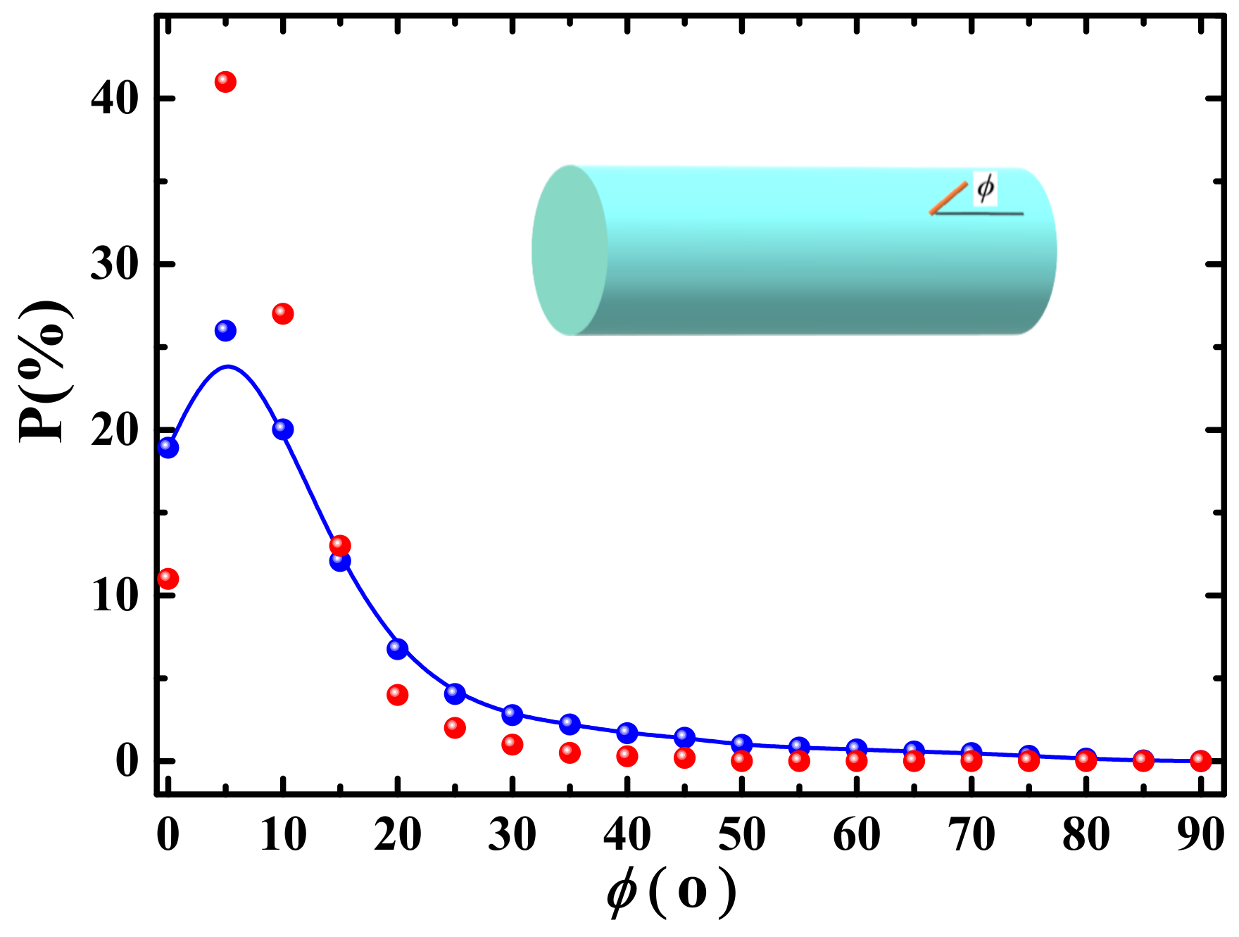
2.2. Probability Density Functions for Particle Orientation

The equation of probability density functions appearing in Equation (11) is:
ψ t + u ψ = D r B p 2 ψ p ( ψ p ˙ ) ,
where DrB is the Brownian rotary diffusion coefficient; ∇p is the gradient operator projected onto the surface of unit sphere; p ˙ is the particle angular velocity [25]:
p ˙ = 1 2 ω p + η 2 ( ε p ε : p p p ) D r I 1 ψ ψ ,
where η = (β2 − 1)/(β2 + 1); ω is the vorticity tensor; DrI is the rotary diffusion coefficient reflecting the interaction between the particles [26] and is given by 0.01 2 ε i j ε j i when DrI is suggested to be isotropic. The Brownian rotary diffusion coefficient DrB in Equation (12) is [27]:
D r B = k b T [ 3.84 π μ L p 3 ( 1 + 0.677 β 0.183 β 2 ) / β 2 ] 2 + [ π μ L p 3 / 3 ( ln β 0.662 + 0.917 β 0.05 β 2 ) ] 2 ,
where kb is the Boltzmann constant; T is the temperature; Lp is the particle length.

2.3. Convection–Diffusion Equations of Particles

Equation of particle number density is:
n t + u j n x j = x j D t B n x j ,
where n is the particle number density; DtB is the Brownian translational diffusion coefficient [27]:
D t B = k b T [ 2 π μ L p / ( ln λ 0.207 + 0.980 β 0.133 β 2 ) ] 2 + [ 4 π μ L p / ( ln λ + 0.839 + 0.185 β + 0.233 β 2 ) ] 2 .
Multiplying the particle number density by vk and then integrating over the entire volume distribution yields:
M k = 0 v k n ( v ) d v .
Taking k = 0, 1, we have:
M 0 = 0 n ( v ) d v = N ,   M 1 = 0 v n ( v ) d v = V ,
in which M0 is the total particle number; M1 denotes the particle volume. Based on M1, the particle volume fraction Φ can be calculated.

3. Numerical Simulation

3.1. Main Steps of Simulation

(1)
Solve Equations (1)–(6) with Φ = 0 (i.e., pure Oldroyd-B fluid) to get u, p and τ.
(2)
Solve Equations (15)–(18) to get n and Φ.
(3)
Substitute Φ into Equations (3), (6), (8)–(10) to get μa, ρt, kt and Dt.
(4)
Substitute u and Equations (13) and (14) into Equation (12) and solve it to get ψ.
(5)
Substitute ψ into Equation (11) to get a2 and a4.
(6)
Substitute Φ, ρt, μa, kt, a2, a4 and Dt into Equations (1)–(7) to get u, p, τ and T.
(7)
Turn to Step (2) based on the new values of u, p and τ if necessary.
(8)
Calculate the friction factor f and Nusselt number Nu:
f = Δ p ρ t ( L / D ) ( U a v 2 / 2 ) ,
N u = h D k t = k t ( T / r ) r = ± D / 2 k t = T r r = ± D / 2 ,
where U a v is the average velocity of the fluid in the flow direction; ∆p is the pressure drop; h is the heat transfer coefficient.

3.2. Numerical Method and Parameters

Finite difference method is used to solve Equations (2), (7), (12) and (15). The diffusion term and convective term are discretized with the central finite differences and the second-order upwind finite difference schemes, respectively. The SIMPLE scheme is employed to deal with the term of velocity-pressure coupling. A staggered mesh system and an alternating direction implicit method are used to solve the discretized equations. The variables such as pressure, axial velocity component uz are located at the centroids of the control volumes while the velocity components ur and uθ over the cross-section are located at the boundaries. The Simpson formula is used to integrate Equation (11). Initially, the particle number density and temperature are uniform, and the orientation of particles is random distribution. On the wall, the velocity satisfies the no-slip condition, the particle number density is zero, and the heat flux is constant.
The nanofluid is a mixture composed of Oldroyd-B fluid and Al2O3 nanoparticles. The reason for using Al2O3 nanoparticle is that such particle is a promising candidate particle due to its high energy density and thermal conductivity, safety, and low cost. The related parameters in the computation are: ρf = 988.2 kg/m3, ρp = 3970 kg/m3, μb = 0.5, kf = 0.62 W/m K, kp = 40 W/m K, Cpf = 4.18 kJ/kg K, Cpp = 0.765 kJ/kg K, kb = 1.38 × 10⁻²³ J/K.

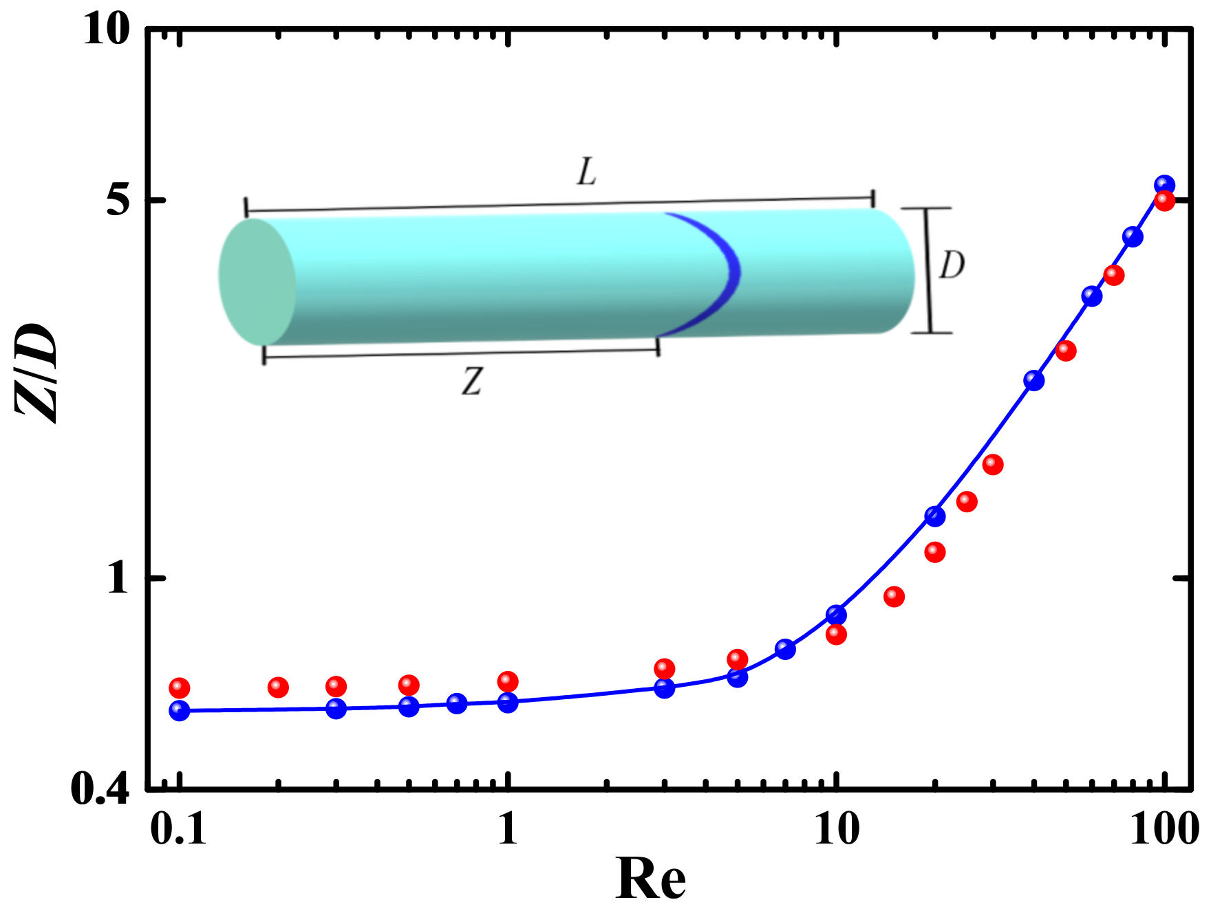
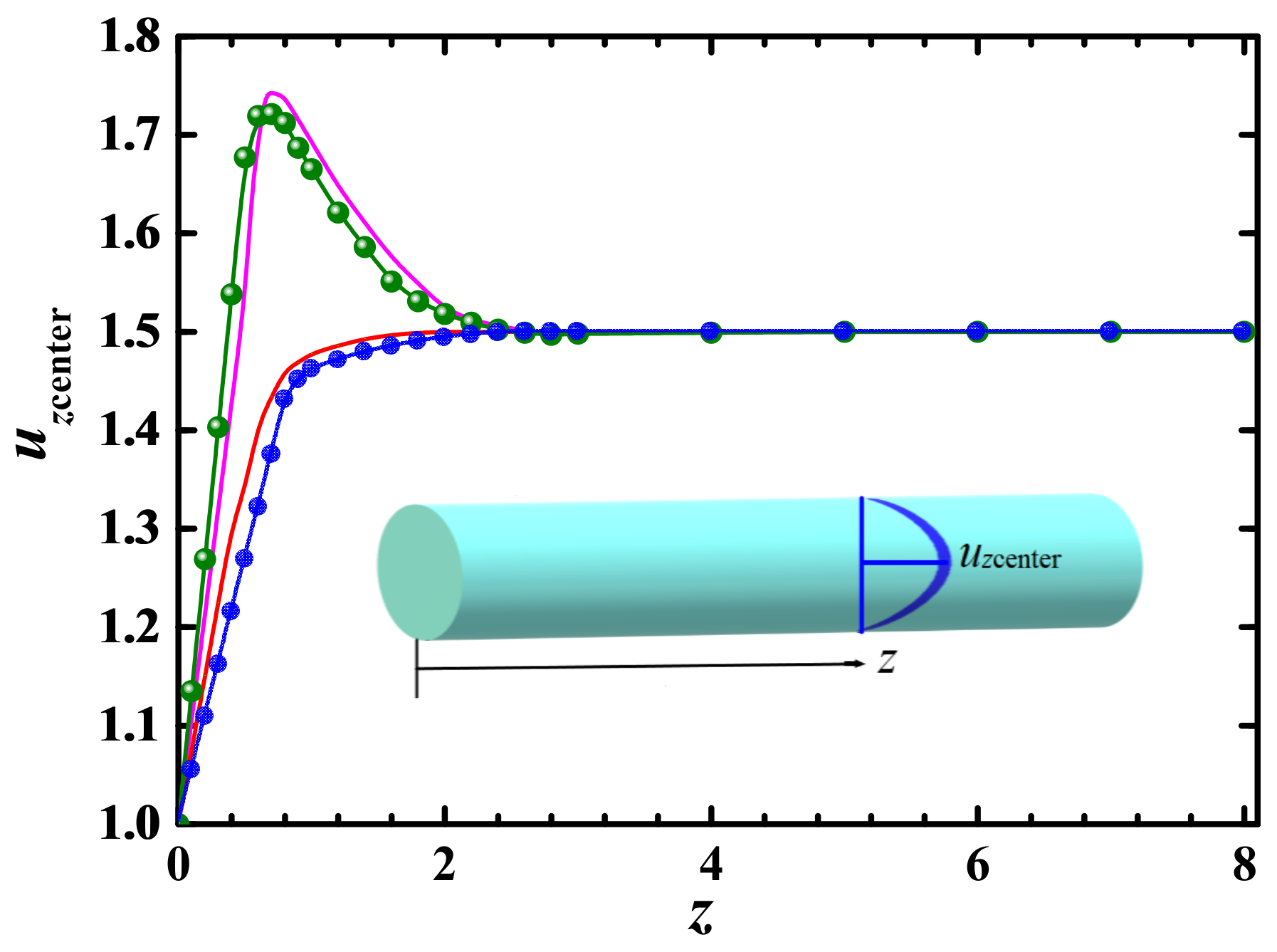
3.3. Mesh Independence Test and Validation

The grid system consists of 128(r) × 32(θ) × 256(z) = 1,048,576 grid points. A uniform grid is used in the θ and z directions, while grids are clustered close to the wall in the r direction. A grid independence test is performed by changing grid points from 112 to 144, 24 to 40 and 216 to 296 in the r, θ and z directions, respectively, and the results are shown in Table 1. A convergence criterion is specified with all the normalized residual errors being less than 10−4.
To validate the numerical method used in the simulation of Oldroyd-B fluid flow, we compare the present numerical results of required pipe length reaching fully developed flow and the centerline velocity along the pipe length with the previous results in channel [28] as shown in Figure 2 and Figure 3. It can be seen that both numerical results are qualitatively consistent.
In order to validate the numerical method used in solving the equation of probability distribution functions for particle orientation, we compare the present numerical results of mean particle orientations in the water-based Al2O3 nanofluids synthesized with cylindrical nanoparticles with the experimental results [29] as shown in Figure 4 and Figure 5 where ϕ is the angle between particle axis and pipe’s axis, and P is the probability. The experiment was performed for the glass fibers suspended in a water tunnel using a combination of a microscopic video-photography system and a computerized image analysis system. A roughly agreement between numerical and experimental results indicates that the numerical method is reasonable and reliable. In Figure 4 a large difference between numerical and experimental data for low angles can be observed. The reason may be that the particles with low angle are mostly located in the boundary layer. It is more difficult to measure and calculate the particle orientation because the boundary layer with larger velocity gradient is close to the wall.

4. Results and Discussion

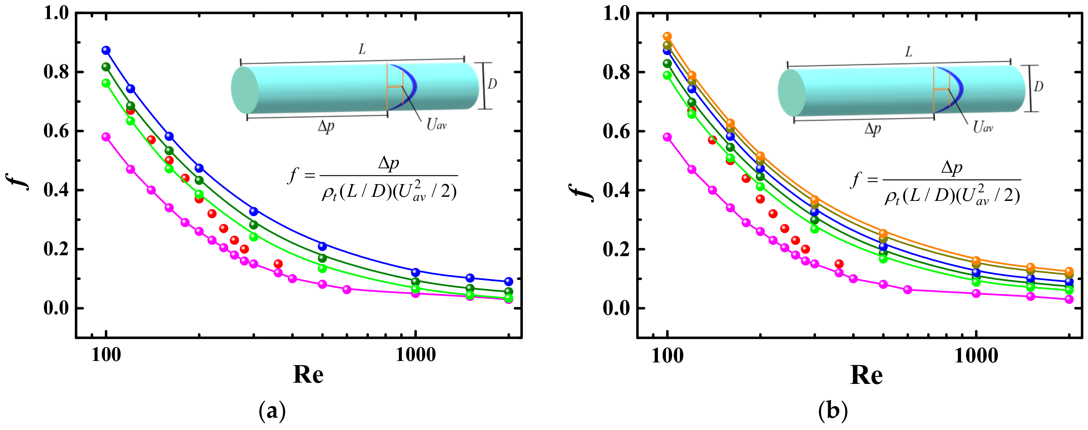
4.1. Friction Factor

The friction factor f which is related to the pressure drop as shown in Equation (19) can be used to measure the shear stress exerting on the flow by the wall. More pumping power is needed to transport equal energy outflows through the same pipeline when f is larger. f is dependent on the physical properties and velocity profile of suspensions.

4.1.1. Effect of Reynolds Number and Weissenberg Number

Variation of friction factor with Reynolds number (Re) is shown in Figure 6a where the experimental results [21] are also presented. The experiment was performed for the flow of polyalphaolefins-Al2O3 nanofluids containing cylindrical particles in a pipe with 1.09 mm in inner diameter and 306 mm in length at 110 ≤ Re ≤ 630. The mean length, diameter and aspect ratio of the particles were 85 nm, 7.0 nm and 12 nm, respectively. The classical Poiseuille law f = 64/Re for pure water is also plotted as a comparison. It can be seen that the friction factor decreases with increasing Re. The friction factor of nanofluids could not follow the Poiseuille law and larger than that of pure water. The reason may be attributed to the difference in the shear stress which is dependent on the viscosity and the radial coordinate due to different shear rates between the wall and the centerline. The larger dynamic viscosity of nanofluids is attributed to the resistance that appears when the Brownian rotation of nanoparticles must be overcome for the particles to align with their major axis near to the flow direction. However, the difference in the friction factor between nanofluids and pure water decreases with increasing Re because the viscosity of nanofluids decreases with Re as well as the shear rate, which is consistent with the experimental results in water-based ZnO nanofluids [30] and in aqueous suspensions of carbon nanotubes [31]. Steele et al. [32] also indicated that only adding carbon nanotubes couldn’t reduce the friction factor. In addition, the friction factor of Oldroyd-B-fluid-based nanofluids is larger than that of water-based ZnO nanofluids, and than that of Oldroyd-B fluid, which is associated with the presence of the additional viscosity μa and μb.
Figure 6b shows the friction factor as a function of Re for different Weissenberg numbers (We) which is the ratio of the first normal stress difference to the shear stress. We can see that the friction factor increases with the increasing We. As We increases, larger first normal stress difference produces an additional extension resistance and results in an increase of the friction factor. The viscosity for the highly elastic fluids with larger We is enhanced as the shear rate increases because the Oldroyd-B fluid is a shear thickening fluid.

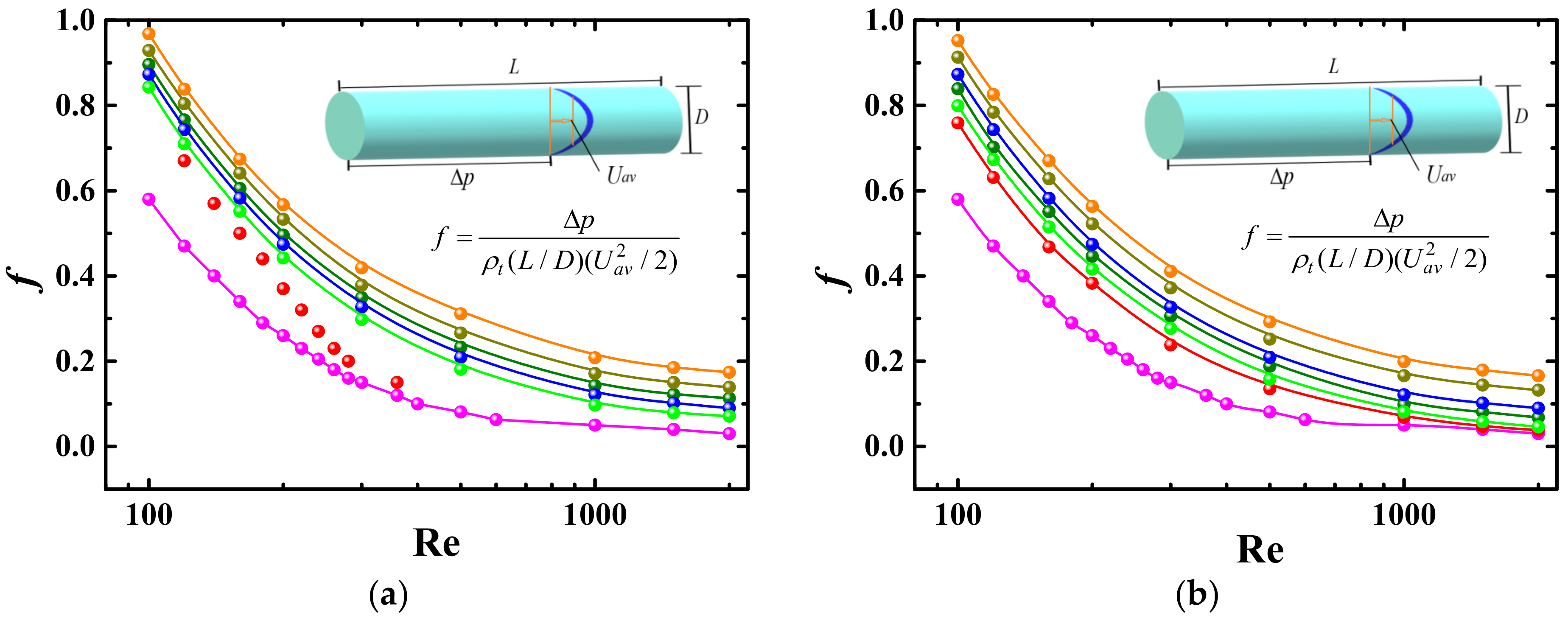
4.1.2. Effect of Particle Aspect Ratio and Volume Concentration
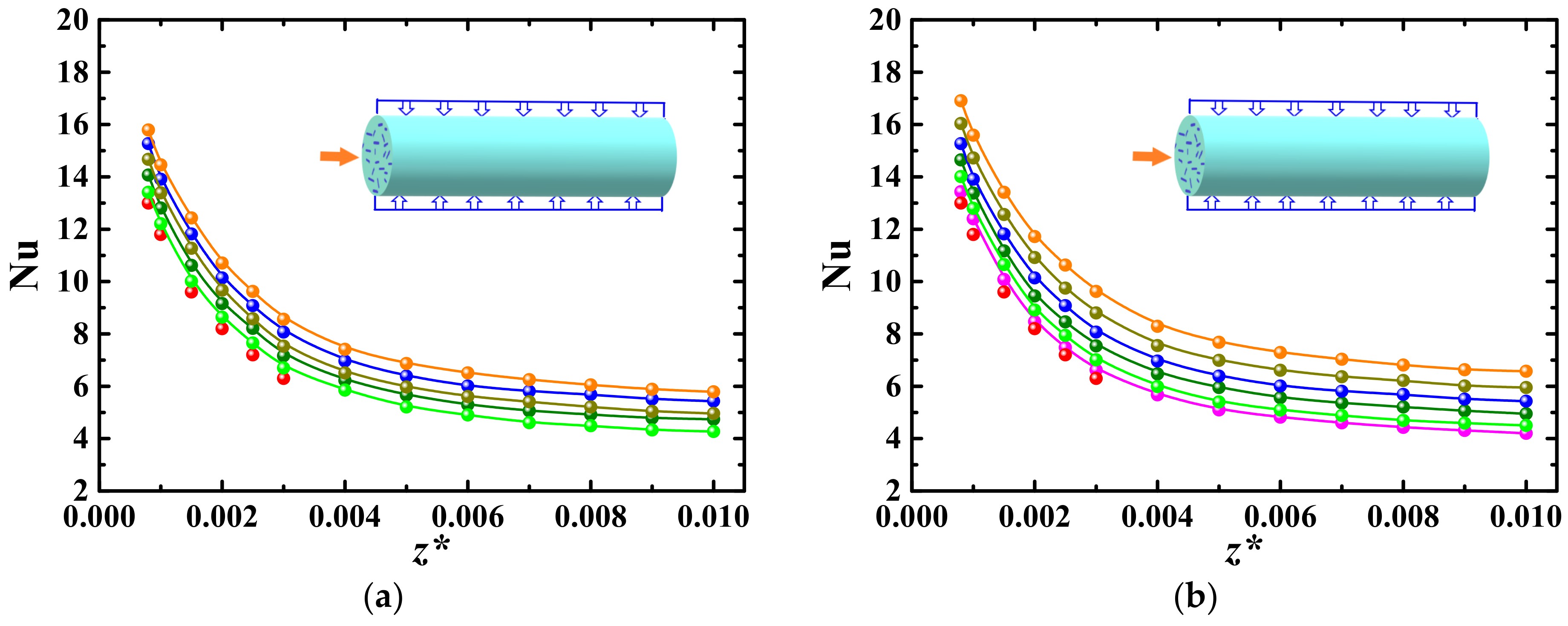
The friction factor as a function of Re for different particle aspect ratios (β) are shown in Figure 7a where the Poiseuille law is also presented as a comparison. It can be seen that, for a fixed Re, the friction factor decreases with increasing β. The reason is that the particles with larger β align more easily with their major axis near to the flow direction under the shear stress, resulting in a decrease of viscosity in a manner similar to shear thinning. It also can be observed that the difference in the friction factor between different β is not so obvious at large β (β = 8, 12 and 16) as that at smaller β (β = 2, 4 and 8) because the orientation distribution of cylindrical particles is not sensitive to β when β is larger than 5 [33].
Figure 7b displays the variation of friction factor with Re for different particle volume concentrations (Φ). The friction factor increases with increasing Φ. From Equation (3) we can see that the viscosity coefficient μa induced by the cylindrical nanoparticles is dependent on Φ and β. As Φ increases, the reduction of the viscosity induced by the alignment of the particles is less obvious than the increase of the viscosity caused by the increase of Φ, resulting in the increase of the friction factor.

4.2. Heat Transfer

In order to understand the heat transfer property of Oldroyd-B-fluid-based nanofluids containing cylindrical particles, we explore the effects of various factors on the Nusselt number (Nu) which is defined as the ratio of convective heat transfer to fluid conduction heat transfer as shown in Equation (20).

4.2.1. Effect of Reynolds Number and Weissenberg Number

Figure 8a shows the values of Nu as a function of z* which is defined as z* = z/(DRePr), where Pr is the Prandtl number. In Figure 8a both numerical and experimental results [21] are given. We can see that Nu decreases with the increase of z*, which is consistent with the general conclusion that Nu is proportional to Re because z* is inversely proportional to Re for fixed z/D and Pr. This may be attributed to that more cylindrical particles align with their major axis near to the flow direction when Re decreases [21], and alignment of particles weakens the interaction between the particles, while such interaction is the main pathway of heat transfer.
The values of Nu of Oldroyd-B-fluid-based nanofluids containing cylindrical particles are larger than that of pure water and Oldroyd-B fluid, i.e., cylindrical particles can promote the convective heat transfer of nanofluids. The mechanism can be analyzed as follows. Firstly, the fluid velocity is different at the two ends of a cylindrical particle, which causes the particle to rotate in the flow and produces a flow disturbance and results in an increase of the convective heat transfer. Secondly, when the particle rotates in the thermal boundary layer, two ends of the particle experience periodically higher and lower temperature in the near-wall region and in the near-bulk region, respectively, causing the heat to be transferred more effectively from one end to another end of the highly conductive particle. Figure 8a also shows that the Oldroyd-B-fluid-based nanofluids have a better effect of enhancing the convective heat transfer than water-based nanofluids.
The Nusselt number, Nu, as a function of z* for different We is shown in Figure 8b where Nu increases with increasing We. As mentioned in Section 4.1.1, the viscosity for the highly elastic fluids with larger We is enhanced as the shear rate increases because the Oldroyd-B fluid is shear thickening fluid. The higher viscosity prevents suspended particles within the fluid from aligning with their major axis near to the flow direction and makes particle interact with each other more frequently, while particle interaction is the main pathway of heat transfer.

4.2.2. Effect of Particle Aspect Ratio and Volume Concentration

The Nusselt number as a function of z* for different β is shown in Figure 9a in which Nu increases with increasing β. Firstly, the apparent viscosity coefficient μa as shown in Equation (3) increases with increasing β, while higher viscosity prevents the particles from aligning with the flow direction and makes particle interact with each other more frequently. Secondly, the cylindrical particles with larger β could produce larger flow disturbance when they rotate in the flow, which results in an enhancement of convective heat transfer. Lastly, there exists a larger heat transfer range for the cylindrical particles with larger β when heat is conducted in the highly conductive particles. Comparing the values of Nu, we can see that the difference in the value of Nu between different β is not so obvious at large β as that at smaller β.
Figure 9b shows the relationship between Nu and Φ. It can be seen that Nu increases with increasing Φ for the cylindrical particles, which is in agreement with the results for the spherical particles [34]. This may be attributed to the fact that the interaction between cylindrical particles is weak at low Φ, which results in a less effective pathway for the thermal energy transport and weaker heat transfer. On the contrary, the interaction between the particles is strong when Φ is high. Strong particle interaction and frequent particle motion produce a large flow disturbance and promote the convective heat transfer.

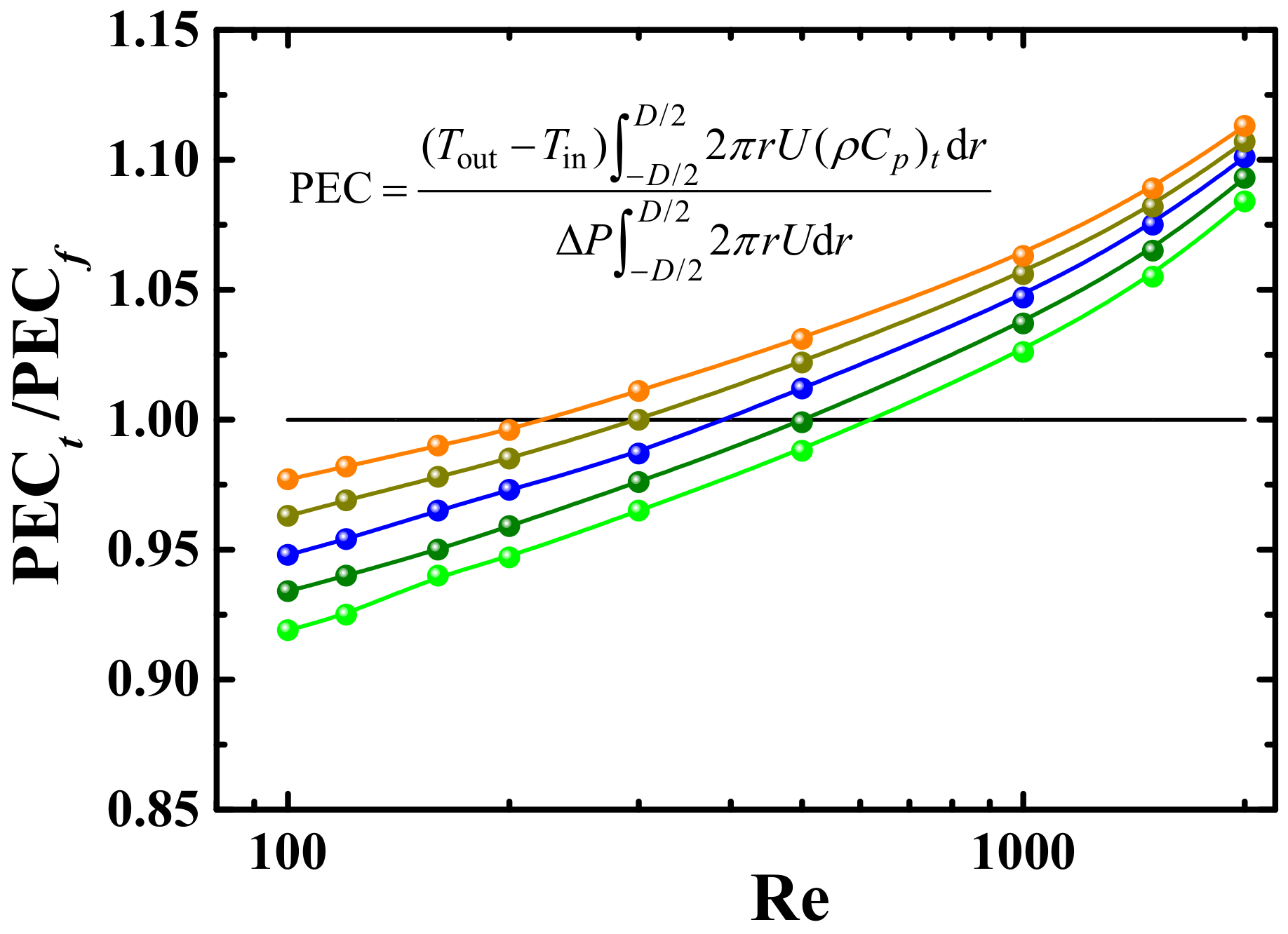
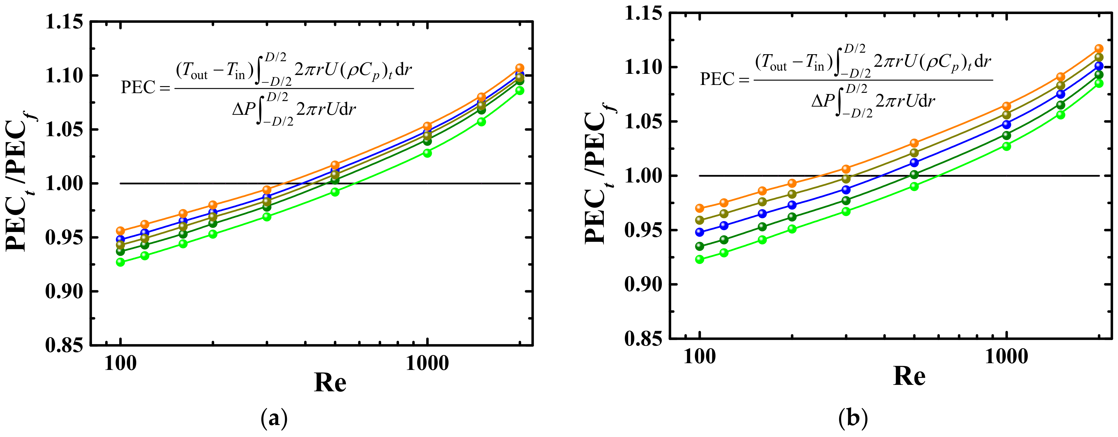
4.3. Performance Evaluation Criterion

As is shown above, the convective heat transfer of Oldroyd-B-fluid-based nanofluids with cylindrical nanoparticles is higher than that of Oldroyd-B fluids. But the results in Figure 6 and Figure 7 showed that the friction factor of Oldroyd-B-fluid-based nanofluids is larger than that of Oldroyd-B fluids. Therefore, it is needed to balance the enhancement of the convective heat transfer and increase in the consumed power when the nanofluids are used. The energy performance evaluation criterion (PEC) can be used to directly relate to the gains and losses of energy [30]:
PEC = ( T o u t T in ) D / 2 D / 2 2 π r U ( ρ C p ) t d r Δ P D / 2 D / 2 2 π r U d r
in which Tin and Tout are the pipe inlet and outlet temperatures, respectively. Expression (21) is the ratio of the transferred heat flow rate to the required consumed power.

4.3.1. Effect of Reynolds Number and Weissenberg Number

PECt/PECf is expressed as the ratio of energy performance evaluation criterion (PEC) for Oldroyd-B-fluid-based nanofluids (PECt) to that for Oldroyd-B fluids (PECf). Figure 10 shows the PECt/PECf as a function of Re for different We. PECt/PECf increases with increasing Re and We. As shown in Section 4.1 and Section 4.2, the friction factor and Nu of Oldroyd-B-fluid-based nanofluids are higher than that of Oldroyd-B fluid. At lower Re (Re < 300~650), the difference in friction factor is larger than that in Nu between Oldroyd-B-fluid-based nanofluids and Oldroyd-B fluid, hence the values of PECt/PECf are less than 1. On the contrary, the values of PECt/PECf are larger than 1 at higher Re because the difference in Nu is larger than that in friction factor. Therefore, it is more effective to use nanofluids containing cylindrical nanoparticles at higher Re and We.

4.3.2. Effect of Particle Aspect Ratio and Volume Concentration

PECt/PECf as a function of Re for different β and Φ are shown in Figure 11.
It can be seen that PECt/PECf increases with the increase of β and Φ. Therefore, it is more effective to use nanofluids containing cylindrical nanoparticles with larger β at higher Φ.

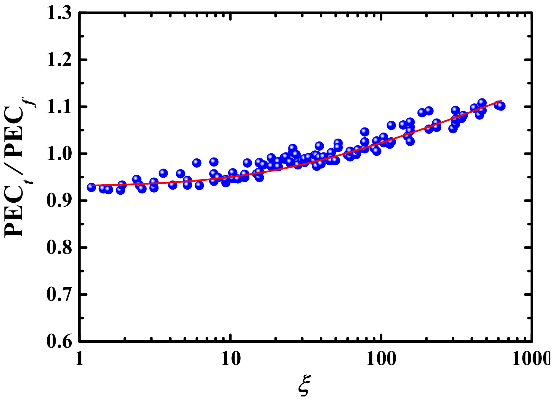
4.3.3. Correlation Model

As shown in Figure 10 and Figure 11, the values of PECt/PECf are directly proportional to Re, We, β and Φ. In order to effectively characterize the effects of above parameters on PECt/PECf, it is needed to build a correlation model relating PECt/PEC to the above parameters. Therefore, we first combine above parameters into a dimensionless parameter:
ξ = Re We β Φ ,
and then build up a relationship between PECt/PECf and ξ based on the Expression (22) and numerical data in Figure 10 and Figure 11 as:
PEC t / PEC f = 0.76781 + 0.05325 ln   ( ξ + 20.68622 ) ,
which is obtained with fitting numerical data in Oringe software. Figure 12 shows the numerical data in Figure 10 and Figure 11 and Expression (23) of fitted curve.

5. Conclusions

Flow and convective heat transfer property of Oldroyd-B-fluid-based nanofluids synthesized with cylindrical particles in a pipe are investigated in order to understand the performance of non-Newtonian fluid based nanofluids with cylindrical particles as a heat transfer medium. The effects of Reynolds number (Re), Weissenberg number (We), particle aspect ratio (β) and volume concentration (Φ) on the friction factor, Nusselt number (Nu) and ratio (PECt/PECf) of energy performance evaluation criterion for Oldroyd-B-fluid-based nanofluids to that for Oldroyd-B fluids are discussed. The main conclusions are summarized as follow:
The friction factor and Nu of Oldroyd-B-fluid-based nanofluids are larger than that of water- based nanofluids and that of Oldroyd-B fluids. The Oldroyd-B-fluid-based nanofluids can enhance the performance of convective heat transfer but result in a larger flow resistance. For the Oldroyd-B-fluid-based nanofluids synthesized with cylindrical particles, the friction factor increases with increasing Re, We and Φ, but with decreasing β, while Nu is enhanced with increasing Re, We, β and Φ.
The PECt/PECf, as a balance of the enhancement of the convective heat transfer to the increase in the consumed power, increases with increasing Re, We, β and Φ. The increase of friction factor is larger and less than that of Nu at lower and higher Re, respectively. Therefore, it is more effective to use Oldroyd-B-fluid-based nanofluids containing cylindrical nanoparticles to improve the convective heat transfer at the conditions of higher Re, We and Φ, and larger β. Finally, the correlation formula of PECt/PECf as a function of Re, We, β and Φ is derived based on the numerical data.

Author Contributions

Conceptualization, J.L. and W.L.; methodology, W.L. and P.Z.; software, W.L. and P.Z.; validation, W.L. and P.Z.; writing, W.L. and P.Z.; resources, W.L. and J.L.; review, J.L. All authors have read and agreed to the published version of the manuscript.

Funding

National Natural Science Foundation of China (Grant 91852102).

Institutional Review Board Statement

Not applicable.

Informed Consent Statement

Not applicable.

Data Availability Statement

Data sharing not applicable.

Conflicts of Interest

The authors declare no conflict of interest.

References

  1. Subedi, J.; Rajendran, S.; Manglik, R.M. Laminar forced convection in viscous shear-thinning liquid flows inside circular pipes: Case for a modified power-law rheology. J. Heat Transf. 2020, 142, 121802. [Google Scholar] [CrossRef]
  2. Costine, A.; Fawell, P.; Chryss, A.; Dahl, S.; Bellwood, J. Development of test procedures based on chaotic advection for assessing polymer performance in high-solids tailings applications. Processes 2020, 9, 731. [Google Scholar] [CrossRef]
  3. Safaei, M.R.; Shadloo, M.S.; Goodarzi, M.; Hadjadj, A.; Goshayeshi, H.R.; Afrand, M.; Kazi, S.N. A survey on experimental and numerical studies of convection heat transfer of nanofluids inside closed conduits. Adv. Mech. Eng. 2016, 8, 16878140. [Google Scholar] [CrossRef]
  4. Martorana, P.; Bayer, I.S.; Steele, A.; Loth, E. Effect of graphite and carbon nanofiber additives on the performance efficiency of a gear pump driven hydraulic circuit using ethanol. Ind. Eng. Chem. Res. 2010, 49, 11363–11368. [Google Scholar] [CrossRef]
  5. Peng, Y.P.; Zahedidastjerdi, A.; Abdollahi, A.; Amindoust, A.; Bahrami, M.; Karimipour, A.; Goodarzi, M. Investigation of energy performance in a U-shaped evacuated solar tube collector using oxide added nanoparticles through the emitter, absorber and transmittal environments via discrete ordinates radiation method. J. Therm. Anal. Calorim. 2020, 139, 2623–2631. [Google Scholar] [CrossRef]
  6. Tian, Z.; Abdollahi, A.; Shariati, M.; Amindoust, A.; Arasteh, H.; Karimipour, A.; Goodarzi, M.; Bach, Q.V. Turbulent flows in a spiral double-pipe heat exchanger optimal performance conditions using an enhanced genetic algorithm. Int. J. Numer. Methods Heat Fluid Flow 2020, 30, 39–53. [Google Scholar] [CrossRef]
  7. Sandeep, N.; Malvandi, A. Enhanced heat transfer in liquid thin film flow of non-newtonian nanofluids embedded with graphene nanoparticles. Adv. Powder Technol. 2016, 27, 2448–2456. [Google Scholar] [CrossRef]
  8. Sulaiman, M.; Ali, A.; Islam, S. Heat and mass transfer in three-dimensional flow of an Oldroyd-B nanofluid with gyrotactic micro-organisms. Math. Probl. Eng. 2018, 2018, 6790420. [Google Scholar] [CrossRef] [Green Version]
  9. Sandeep, N.; Sulochana, C. Momentum and heat transfer behavior of Jeffrey, Maxwell and Oldroyd-B nanofluids past a stretching surface with non-uniform heat source/sink. AIN Shams Eng. J. 2018, 9, 517–524. [Google Scholar] [CrossRef] [Green Version]
  10. Aziz, A.; Muhammad, T.; Alsaedi, A.; Hayat, T. An optimal study for 3D rotating flow of Oldroyd-B nanofluid with convectively heated surface. J. Braz. Soc. Mech. Sci. Eng. 2019, 41, 1–11. [Google Scholar] [CrossRef]
  11. Masuda, H.; Ebata, A.; Teramae, K.; Hishinuma, N. Alternation of thermal conductivity and viscosity of liquid by dispersing ultra-fine particles (dispersion of γ-Al2O3, SiO2 and TiO2 ultra-fine particles). Netsu Bussei 1993, 7, 227–233. [Google Scholar] [CrossRef]
  12. Ahmed, Z.; Al-Qahtani, A.; Nadeem, S.; Saleem, S. Computational study of mhd nanofluid flow possessing micro-rotational inertia over a curved surface with variable thermophysical properties. Processes 2019, 7, 387. [Google Scholar] [CrossRef] [Green Version]
  13. Nan, C.; Shi, Z.; Lin, Y. A simple model for thermal conductivity of carbon nanotube-based composites. Chem. Phys. Lett. 2003, 375, 666–669. [Google Scholar] [CrossRef]
  14. Murshed, S.; Leong, K.; Yang, C. Investigations of thermal conductivity and viscosity of nanofluids. Int. J. Therm. Sci. 2008, 47, 560–568. [Google Scholar] [CrossRef]
  15. Patel, H.E.; Anoop, K.B.; Sundararajan, T.; Das, S.K. Model for thermal conductivity of CNT-nanofluids. Bull. Mater. Sci. 2008, 31, 387–390. [Google Scholar] [CrossRef]
  16. Elias, M.M.; Miqdad, M.; Mahbubul, I.M.; Saidur, R.; Kamalisarvestani, M.; Sohel, M.R.; Hepbasli, A.; Rahim, N.A.; Amalina, M.A. Effect of nanoparticle shape on the heat transfer and thermodynamic performance of a shell and tube heat exchanger. Int. Commun. Heat Mass Transf. 2013, 44, 93–99. [Google Scholar] [CrossRef]
  17. Ghosh, M.M.; Ghosh, S.; Pabi, S.K. Effects of particle shape and fluid temperature on heat-transfer characteristics of nanofluids. J. Mater. Eng. Perform. 2013, 22, 1525–1529. [Google Scholar] [CrossRef]
  18. Lin, J.Z.; Xia, Y.; Ku, X.K. Friction factor and heat transfer of nanofluids containing cylindrical nanoparticles in laminar pipe flow. J. Appl. Phys. 2014, 116, 133513. [Google Scholar] [CrossRef]
  19. Shaikh, S.; Lafdi, K.; Ponnappan, R. Thermal conductivity improvement in Carbon nanoparticle doped PAO oil: An experimental study. J. Appl. Phys. 2007, 101, 64302. [Google Scholar] [CrossRef] [Green Version]
  20. Nelson, I.C.; Banerjee, D.; Ponnappan, R. Flow loop experiments using polyalphaolefin nanofluids. J. Thermophys. Heat Transf. 2009, 23, 752–761. [Google Scholar] [CrossRef]
  21. Yu, L.; Liu, D.; Botz, F. Laminar convective heat transfer of alumina-polyalphaolefin nanofluids containing spherical and non-spherical nanoparticles. Exp. Therm. Fluid Sci. 2012, 37, 72–83. [Google Scholar] [CrossRef]
  22. Batchelor, G.K. Stress generated in a non-dilute suspension of elongated particles by pure straining motion. J. Fluid Mech. 1971, 46, 813–829. [Google Scholar] [CrossRef]
  23. Mackaplow, M.B.; Shaqfeh, E.S.G. A Numerical study of the rheological properties of suspensions of rigid, non-Brownian fibres. J. Fluid Mech. 1996, 329, 155–186. [Google Scholar] [CrossRef]
  24. Zhang, X.; Gu, H.; Fujii, M. Effective thermal conductivity and thermal diffusivity of nanofluids containing spherical and cylindrical nanoparticles. Exp. Therm. Fluid Sci. 2007, 31, 593–599. [Google Scholar] [CrossRef]
  25. Cintra, J.S.; Tucker, C.L. Orthotropic closure approximations for flow-induced fiber orientation. J. Rheol. 1995, 39, 1095–1122. [Google Scholar] [CrossRef]
  26. Koch, D.L. A model for orientational diffusion in fiber suspensions. Phys. Fluids 1995, 7, 2086–2088. [Google Scholar] [CrossRef]
  27. Li, G.; Tang, J.X. Diffusion of actin filaments within a thin layer between two walls. Phys. Rev. E 2004, 69, 061921. [Google Scholar] [CrossRef] [PubMed]
  28. Yapici, K.; Karasozen, B.; Uludag, Y. Numerical analysis of viscoelastic fluids in steady pressure-driven channel flow. J. Fluids Eng. 2012, 134, 051206. [Google Scholar] [CrossRef]
  29. Bernstein, O.; Shapiro, M. Direct determination of the orientation distribution function of cylindrical particles immersed in laminar and turbulent shear flows. J. Aerosol Sci. 1994, 25, 113–136. [Google Scholar] [CrossRef]
  30. Ferrouillat, S.; Bontemps, A.; Poncelet, O.; Soriano, O.; Gruss, J.A. Influence of nanoparticle shape factor on convective heat transfer and energetic performance of water-based SiO2 and ZnO nanofluids. Appl. Therm. Eng. 2013, 51, 839–851. [Google Scholar] [CrossRef]
  31. Ko, G.H.; Heo, K.; Lee, K.; Kim, D.S.; Kim, C.; Sohn, Y.; Choi, M. An Experimental study on the pressure drop of nanofluids containing carbon nanotubes in a horizontal tube. Int. J. Heat Mass Transf. 2007, 50, 4749–4753. [Google Scholar] [CrossRef]
  32. Steele, A.; Bayer, I.S.; Loth, E. Pipe flow drag reduction effects from carbon nanotube additives. Carbon 2014, 77, 1183–1186. [Google Scholar] [CrossRef]
  33. Krushkal, E.M.; Gallily, I. On the orientation distribution function of non-spherical aerosol particles in a general shear flow—II. The turbulent case. J. Aerosol Sci. 1988, 19, 197–211. [Google Scholar] [CrossRef]
  34. Zamzamian, A.; Oskouie, S.N.; Doosthoseini, A.; Joneidi, A.; Pazouki, M. Experimental investigation of forced convective heat transfer coefficient in nanofluids of Al2O3/EG and CuO/EG in a double pipe and plate heat exchangers under turbulent flow. Exp. Therm. Fluid Sci. 2011, 35, 495–502. [Google Scholar] [CrossRef]
Figure 2. Required pipe length reaching fully developed flow with respect to Re. : numerical result in channel flow [28], : present result.
Processes 09 00647 g002
Figure 3. Centerline velocity along the pipe length for different Weissenberg number (Re = 0.001) result in channel flow [28]: : We = 0.1; : We = 0.6, present result: : We = 0.1; : We = 0.6.
Processes 09 00647 g003
Figure 4. Probability distribution of mean particle orientation (λ = 10, Re = 1600). : present result; : experimental results [29].
Processes 09 00647 g004
Figure 5. Relation between mean particle orientation and Reynolds number (λ = 10). : present result; : experimental results [29].
Processes 09 00647 g005
Figure 6. Friction factor as a function of Reynolds number (β = 12, Φ = 1.3 v%, We = 1.0). (a) Comparison of different fluid. : water; : present result (Oldroyd-B fluid, μa = 0); : present result (water/Al2O3, μb = 0); : present result (Oldroyd-B fluid/Al2O3); : experiment (polyalphaolefins/Al2O3, μb = 0, [21]). (b) Effect of Weissenberg number. : water; : We = 0.1; : We = 0.6; : We = 1.0; : We = 1.5; : We = 2.0; : experiment (polyalphaolefins/Al2O3, μb = 0, [21]).
Processes 09 00647 g006
Figure 7. Friction factor as a function of Reynolds number for different particle aspect ratio and concentration. (a) Effect of particle aspect ratio (We = 1, Φ = 1.3 v%,). : water; : β = 16; : β = 12; : β = 8; : β = 4; : β = 2; : experiment (polyalphaolefins/Al2O3, μb = 0, [21]). (b) Effect of particle concentration (β = 12, We = 1). : water; ⸺●⸺: Φ = 0 v% (Oldroyd-B fluid); : Φ = 0.1 v%; : 0.65 v%; : Φ = 1.3 v%; : Φ = 1.9 v%; : Φ = 2.5 v%.
Processes 09 00647 g007
Figure 8. Nusselt number as a function of z* (β = 12, Φ = 1.3 v%, We = 1.0). (a) Comparison of different fluid. : experiment (polyalphaolefins/Al2O3, μb = 0, [21]); : present result (Oldroyd-B fluid, μa = 0); : present results (water/Al2O3, μb = 0); : present results (Oldroyd-B fluid/Al2O3). (b) Effect of Weissenberg number. : experiment (polyalphaolefins/Al2O3, μb = 0, [21]); : We = 0.1; : We = 0.6; : We = 1.0; : We = 1.5; : We = 2.0.
Processes 09 00647 g008
Figure 9. Nusselt number as a function of z* for different particle aspect ratio and concentration. (a) Effect of particle aspect ratio (We = 1, Φ = 1.3 v%,). : experiment (polyalphaolefins/Al2O3, μb = 0, [21]); : β = 2; : β = 4; : β = 8; : β = 12; : β = 16. (b) Effect of particle concentration (β = 12, We = 1). : experiment (polyalphaolefins/Al2O3, μb = 0, [21]); : Φ = 0 v%; : Φ = 0.1 v%; : 0.65 v%; : Φ = 1.3 v%; : Φ = 1.9 v%; : Φ = 2.5 v%.
Processes 09 00647 g009
Figure 10. Performance evaluation criterion (PEC)t/PECf as a function of Reynolds number for different Weissenberg numbers (β = 12, Φ = 1.3 v%). : We = 0.1; : We = 0.6; : We = 1.0; : We = 1.5; : We = 2.0.
Processes 09 00647 g010
Figure 11. PECt/PECf as a function of Reynolds number for different particle aspect ratio and concentration. (a) Effect of particle aspect ratio (We = 1, Φ = 1.3 v%,). : β = 2; : β = 4; : β = 8; : β = 12; : β = 16. (b) Effect of particle concentration (β = 12, We = 1). : Φ = 0.1 v%; : 0.65 v%; : Φ = 1.3 v%; : Φ = 1.9 v%; : Φ = 2.5 v%.
Processes 09 00647 g011
Figure 12. Relationship between PECt/PECf and dimensionless parameter ξ. : numerical data; ⸺⸺: Expression (23).
Processes 09 00647 g012
Table 1. Values of M1 when changing grid points.
r × θ × SM1r × θ × SM1r × θ × SM1
112 × 32 × 2561.16582128 × 24 × 2561.16580128 × 32 × 2161.16575
120 × 32 × 2561.16564128 × 28 × 2561.16563128 × 32 × 2361.16561
128 × 32 × 2561.16549128 × 32 × 2561.16549128 × 32 × 2561.16549
136 × 32 × 2561.16541128 × 36 × 2561.16543128 × 32 × 2761.16544
144 × 32 × 2561.16536128 × 40 × 2561.16539128 × 32 × 2961.16542
Publisher’s Note: MDPI stays neutral with regard to jurisdictional claims in published maps and institutional affiliations.

