Lattice Boltzmann Simulation of Ferrofluids Film Boiling


Abstract
:1. Introduction
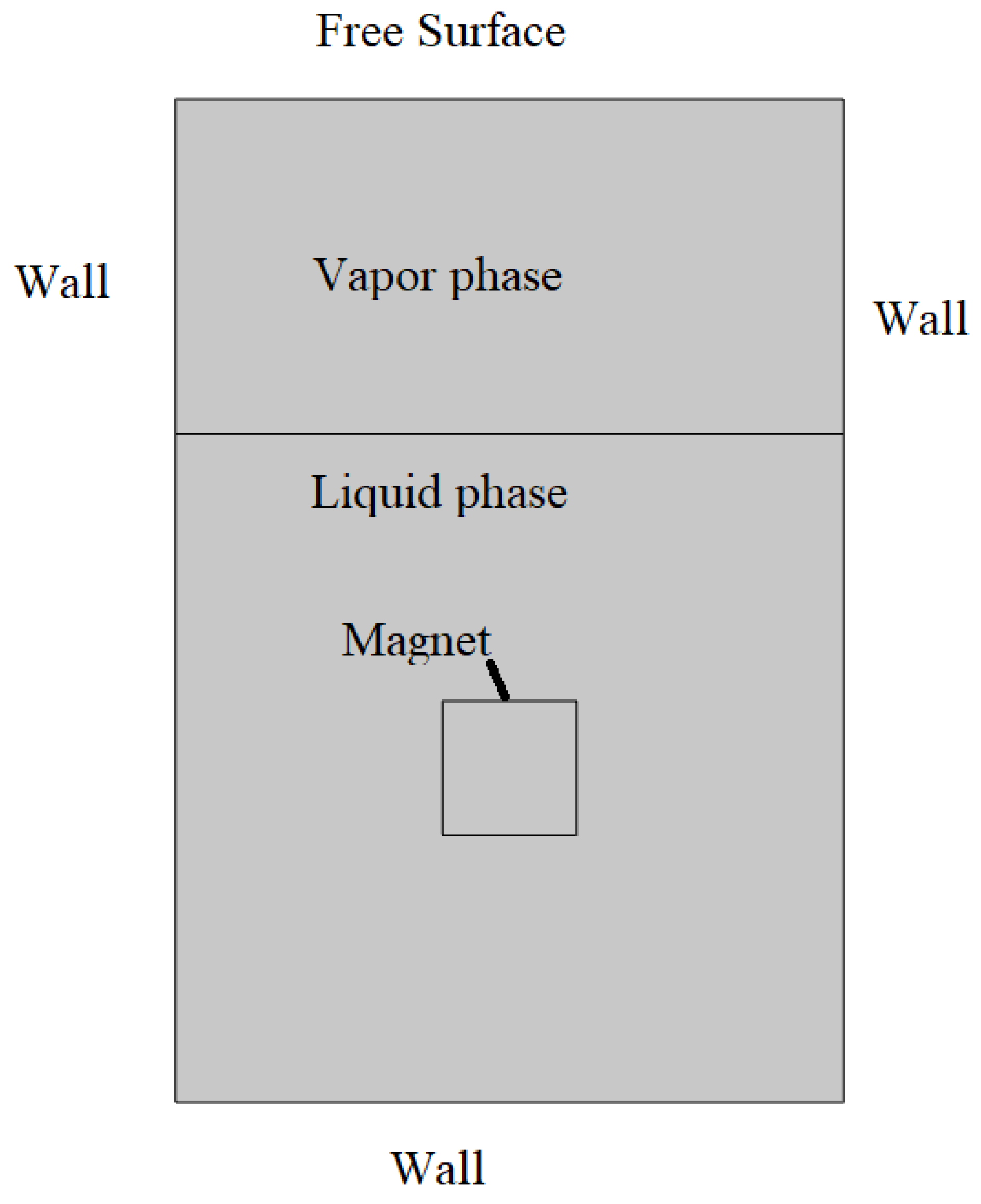
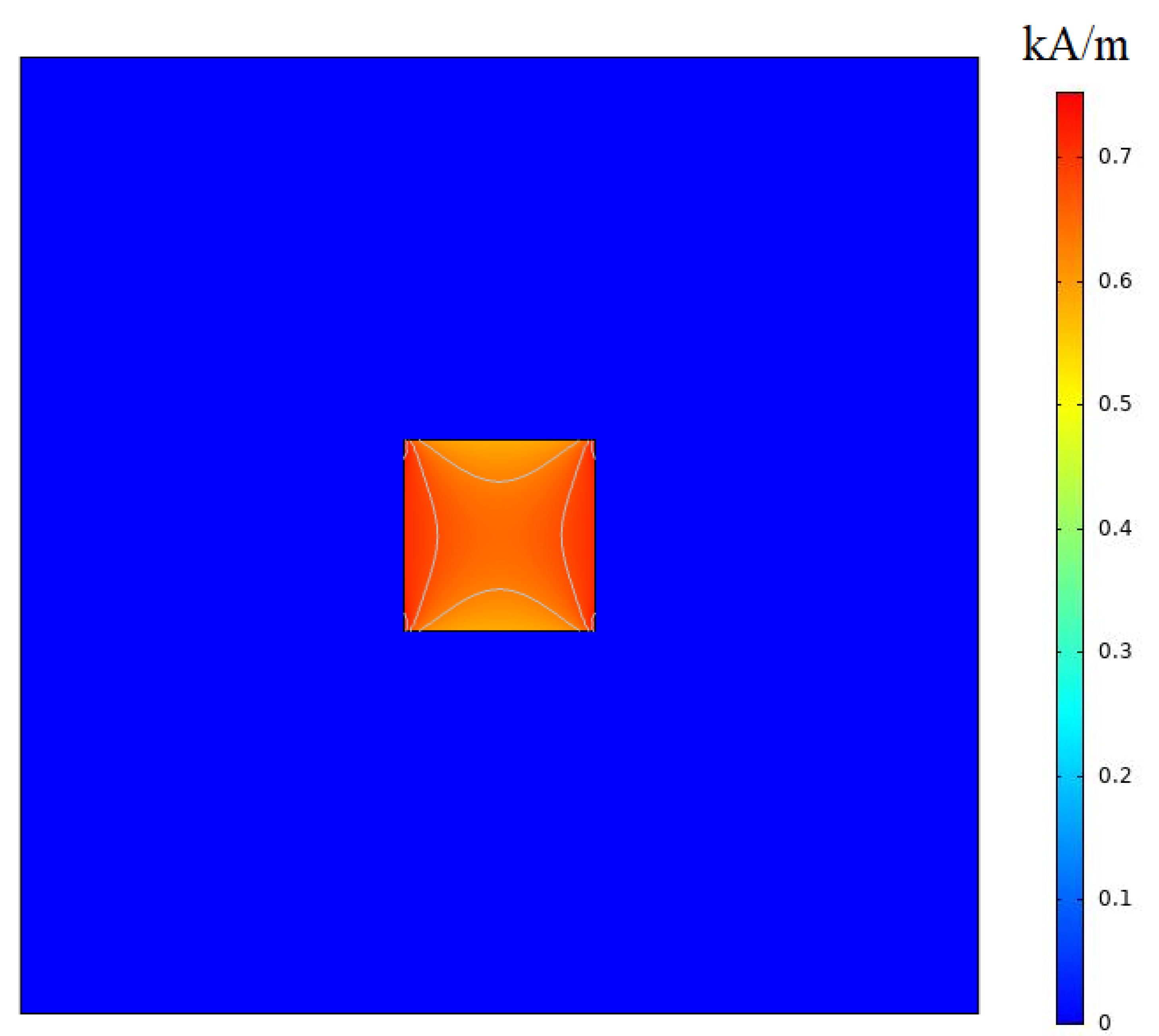
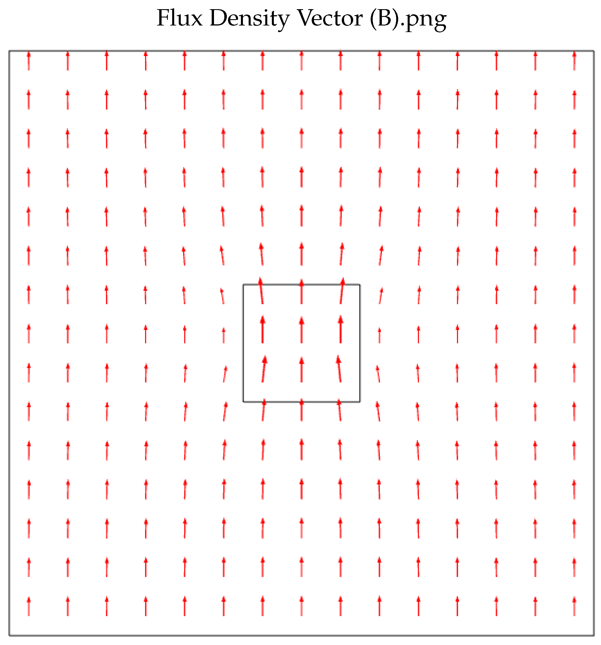
2. Mathematical Modeling
3. Numerical Modeling
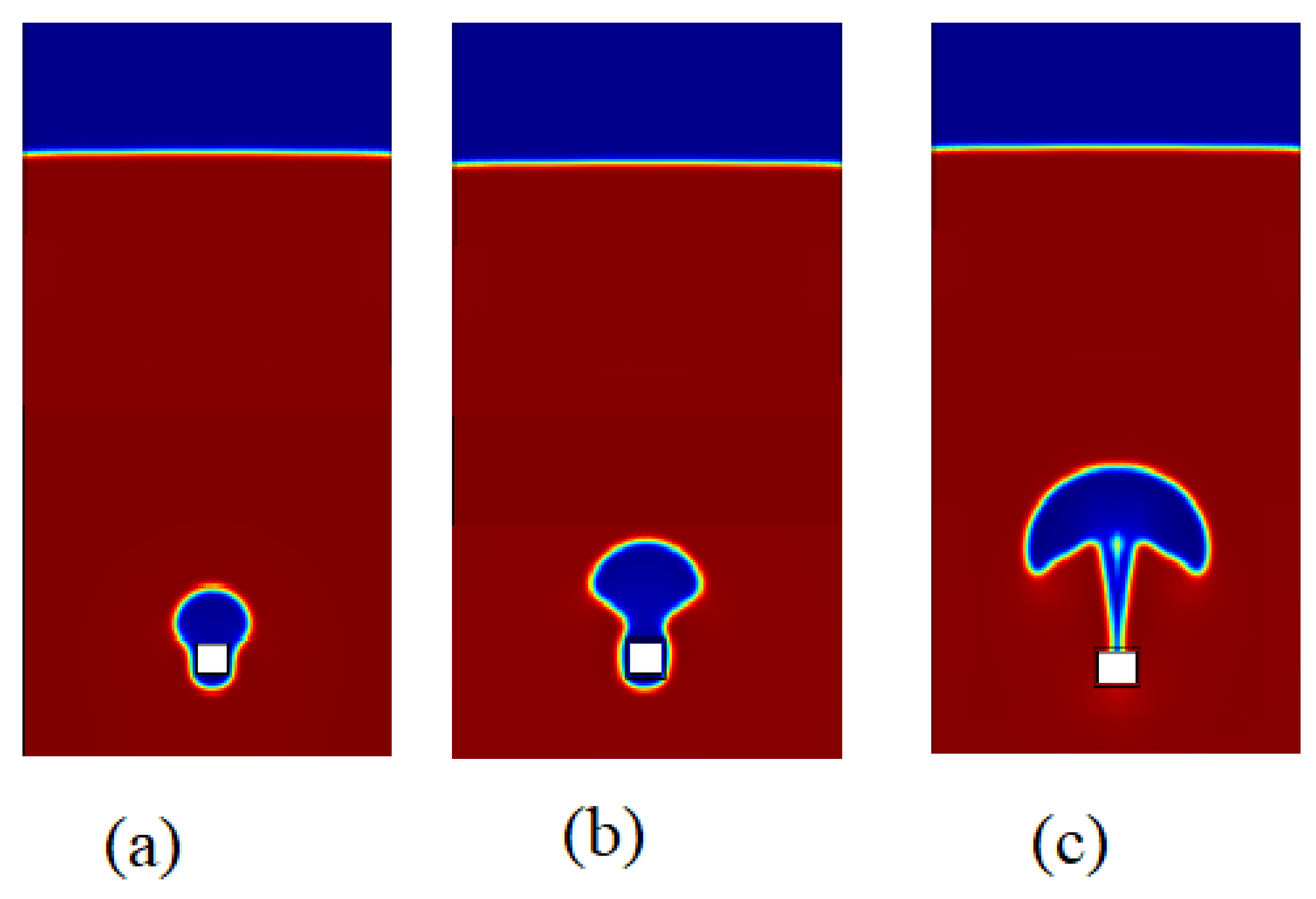
4. Results
5. Conclusions
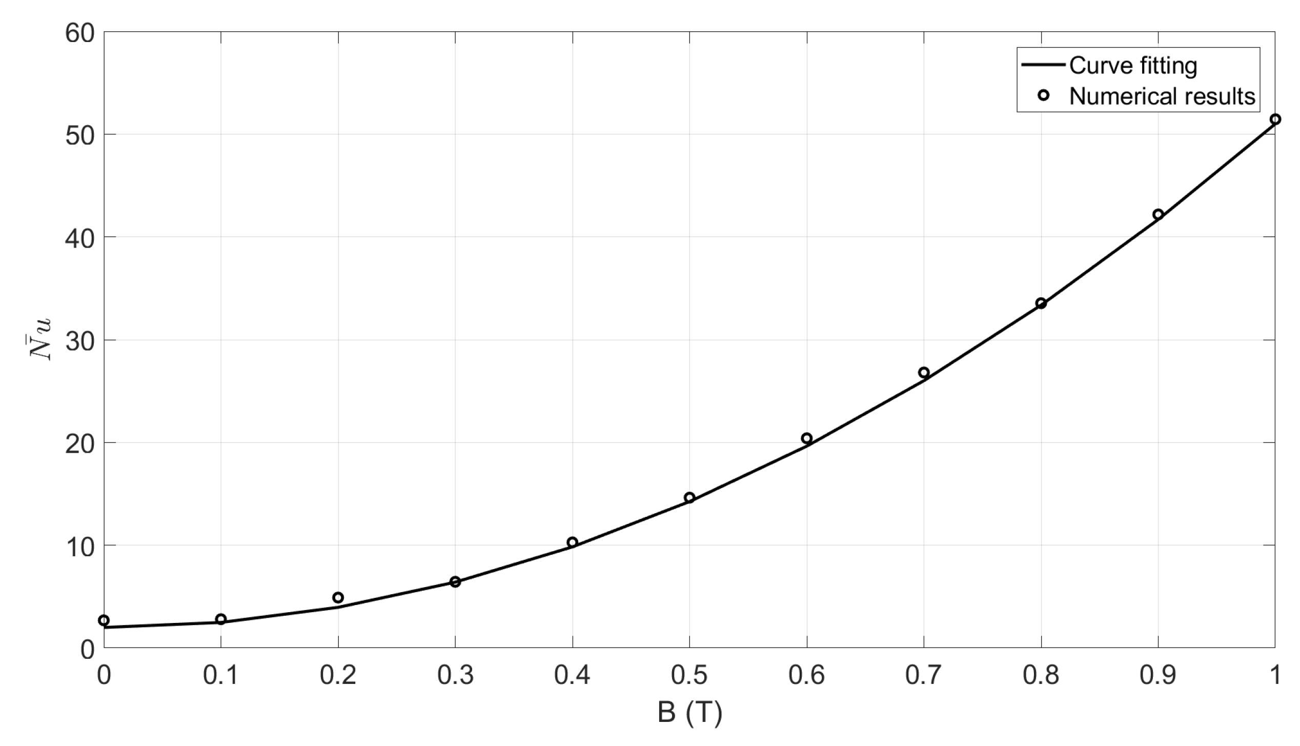
- (1)
- By the increase of magnitude magnetic flux, the heat transfer increased.
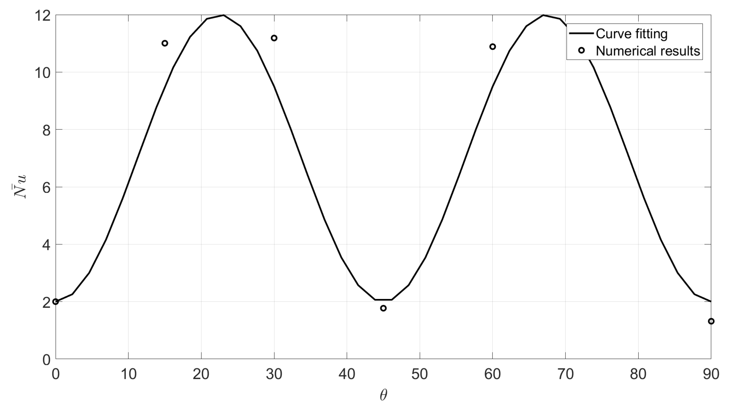
- (2)
- By the increase of angle of application of magnetic flux, the heat transfer increased. The increase is a function of the magnet angle.
- (3)
- A correlation to obtain the Nusselt number was presented.
Funding
Conflicts of Interest
Nomenclature
| specific heat capacity (J/kg K) | |
| g | acceleration due to gravity (m/s) |
| h | heat transfer coefficient (W/(m K)) |
| latent heat (J/kg) | |
| k | thermal conductivity (W/m K) |
| L | characteristic length (m) |
| Nu | local Nusselt number |
| mean Nusselt number for whole heater surface | |
| P | Pressure (N/m) |
| Pr | Prandtl number |
| Heat flux (W/m) | |
| Ra | Rayleigh number |
| t | Time (s) |
| T | temperature (K) |
| u | vapour velocity in x-direction (m/s) |
| v | velocity normal to the direction of flow (m/s) |
| x | horizontal coordinate (m) |
| y | coordinate measured distance normal to heater surface (m) |
| Greek symbols | |
| Void fraction | |
| vapour film thickness (m) | |
| absolute viscosity (kg/ms) | |
| kinematic viscosity (m/s) | |
| density (kg/m) | |
| angle measured from horizontal of heater; Azimuthal angle (rad or degrees) angle of inclination with respect to the horizontal plane | |
| Subscripts | |
| eq | Equilibrium |
| f | Saturated liquid |
| FB | Film boiling |
| l | liquid |
| m | Mixture, mixture average |
| NB | Nucleate boiling |
| ref | Reference |
| s | vapour at saturation temperature |
| sat | Saturation |
| v | vapour |
| w | heater wall |
| ∞ | Ambient associated with a large surface |
References
- Sedaghatkish, A.; Sadeghiseraji, J.; Jamalabadi, M.Y.A. Numerical simulation of magnetic nanofluid (MNF) film boiling on cylindrical heated magnet using phase field method. Int. J. Heat Mass Transf. 2020, 152, 119546. [Google Scholar] [CrossRef]
- Liang, G.; Mudawar, I. Review of pool boiling enhancement by surface modification. Int. J. Heat Mass Transf. 2019, 128, 892–933. [Google Scholar] [CrossRef]
- Kandlikar, S.G. Fundamental issues related to flow boiling in minichannels and microchannels. Exp. Therm. Fluid Sci. 2002, 26, 389–407. [Google Scholar] [CrossRef]
- Kandlikar, S.G.; Balasubramanian, P. An extension of the flow boiling correlation to transition, laminar, and deep laminar flows in minichannels and microchannels. Heat Transf. Eng. 2004, 25, 86–93. [Google Scholar] [CrossRef]
- Shojaeian, M.; Koşar, A. Pool boiling and flow boiling on micro-and nanostructured surfaces. Exp. Therm. Fluid Sci. 2015, 63, 45–73. [Google Scholar] [CrossRef]
- Phan, H.T.; Caney, N.; Marty, P.; Colasson, S.; Gavillet, J. Surface wettability control by nanocoating: The effects on pool boiling heat transfer and nucleation mechanism. Int. J. Heat Mass Transf. 2009, 52, 5459–5471. [Google Scholar] [CrossRef]
- Liter, S.G.; Kaviany, M. Pool-boiling CHF enhancement by modulated porous-layer coating: Theory and experiment. Int. J. Heat Mass Transf. 2001, 44, 4287–4311. [Google Scholar] [CrossRef]
- Liang, G.; Mudawar, I. Review of pool boiling enhancement with additives and nanofluids. Int. J. Heat Mass Transf. 2018, 124, 423–453. [Google Scholar] [CrossRef]
- Abe, Y. Self-rewetting fluids: Beneficial aqueous solutions. Ann. N. Y. Acad. Sci. 2006, 1077, 650–667. [Google Scholar] [CrossRef]
- Wang, L.; Yue, X.; Chong, D.; Chen, W.; Yan, J. Experimental investigation on the phenomenon of steam condensation induced water hammer in a horizontal pipe. Exp. Therm. Fluid Sci. 2018, 91, 451–458. [Google Scholar] [CrossRef]
- Levin, A.A.; Tairov, E.A.; Spiryaev, V.A. Self-excited pressure pulsations in ethanol under heater subcooling. Thermophys. Aeromech. 2017, 24, 61–71. [Google Scholar] [CrossRef]
- Clough, R.W.; Penzien, J. Dynamics of Structures; McGraw-Hill Book Company: New York City, NY, USA, 1975; Volume 3, pp. 310–311. [Google Scholar]
- Ivey, H.J.; Morris, D.J. Critical Heat Flux of Saturation and Subcooled Pool Boiling in Water at Atmospheric Pressure; Begel House Inc.: Danbury, CT, USA, 1966; Volume 9, pp. 129–1420. [Google Scholar]
- Zuber, N. Hydrodynamic Aspect of Boiling Heat Transfer. Ph.D. Thesis, University of California, Los Angeles, CA, USA, 1959. [Google Scholar]
- Kutateladze, S.S. Heat Transfer in Condensation and Boiling; AEC-Transl.: Washington, DC, USA, 1952; Volume 5, pp. 3700–3770. [Google Scholar]
- Inada, S.; Miyasaka, Y.; Sakamoto, S.; Chandratilleke, G.R. Liquid-solid contact state in subcooled pool transition boiling system. J. Heat Transf. 1986, 108, 219–221. [Google Scholar] [CrossRef]
- Unno, N.; Yuki, K.; Kibushi, R.; Suzuki, K. Advanced boiling cooling technology using a compact vessel with a low water level. Trans. Jpn. Inst. Electron. Packag. 2018, 11, E18-010. [Google Scholar] [CrossRef] [Green Version]
- Sjölander, K.; Beskow, J. Wavesurfer-an open source speech tool. In Proceedings of the Sixth International Conference on Spoken Language Processing, Beijing, China, 16–20 October 2000. [Google Scholar]
- Katto, Y.; Yokoya, S.; Teraoka, K. Experimental study of nucleate boiling in case of making interference-plate approach to the heating surface. In Proceedings of the 3th International Heat Transfer Conference, Chicago, IL, USA, 7–12 August 1966; Volume 3, pp. 219–227. [Google Scholar]
- Zhao, Y.; Tsuruta, T.; Ji, C. Experimental study of nucleate boiling heat transfer enhancement in a confined space. Exp. Therm. Fluid Sci. 2003, 28, 9–16. [Google Scholar] [CrossRef]
- Fakhari, A.; Bolster, D. Diffuse interface modeling of three-phase contact line dynamics on curved boundaries: A lattice Boltzmann model for large density and viscosity ratios. J. Comput. Phys. 2017, 334, 620–638. [Google Scholar] [CrossRef] [Green Version]
- Abdollahzadeh Jamalabadi, M.Y. LBM simulation of piezo fan in square enclosure. Int. J. Numer. Methods Heat Fluid Flow 2019, 30, 401–426. [Google Scholar] [CrossRef]
- Sadeghi, R.; Shadloo, M.S.; Jamalabadi, M.Y.A.; Karimipour, A. A three-dimensional lattice Boltzmann model for numerical investigation of bubble growth in pool boiling. Int. Commun. Heat Mass Transf. 2016, 79, 58–66. [Google Scholar] [CrossRef]
- De Rosis, A.; Huang, R.; Coreixas, C. Universal formulation of central-moments-based lattice Boltzmann method with external forcing for the simulation of multiphysics phenomena. Phys. Fluids 2019, 31, 117102. [Google Scholar] [CrossRef] [Green Version]
- Saito, S.; de Rosis, A.; Fei, L.; Luo, K.H.; Ebihara, K.; Kaneko, A.; Abe, Y.; Koyama, K. Lattice Boltzmann modeling and simulation of forced-convection boiling on a cylinder. arXiv 2019, arXiv:1912.02018. [Google Scholar]
- Saito, S.; De Rosis, A.; Festuccia, A.; Kaneko, A.; Abe, Y.; Koyama, K. Color-gradient lattice Boltzmann model with nonorthogonal central moments: Hydrodynamic melt-jet breakup simulations. Phys. Rev. E 2018, 98, 013305. [Google Scholar] [CrossRef] [Green Version]
- Saito, S.; Abe, Y.; Koyama, K. Lattice Boltzmann modeling and simulation of liquid jet breakup. Phys. Rev. E 2017, 96, 013317. [Google Scholar] [CrossRef] [PubMed] [Green Version]
- De Rosis, A. Central-moments–based lattice Boltzmann schemes with force-enriched equilibria. EPL (Europhys. Lett.) 2017, 117, 34003. [Google Scholar] [CrossRef]
- De Rosis, A. Non-orthogonal central moments relaxing to a discrete equilibrium: A D2Q9 lattice Boltzmann model. EPL (Europhys. Lett.) 2016, 116, 44003. [Google Scholar] [CrossRef]
- Krakov, M.S.; Nikiforov, I.V. Natural convection in a horizontal cylindrical enclosure filled with a magnetic nanofluid: Influence of the uniform outer magnetic field. Int. J. Therm. Sci. 2018, 133, 41–54. [Google Scholar] [CrossRef]
- Krakov, M.S.; Nikiforov, I.V. Influence of the shape of the inner boundary on thermomagnetic convection in the annulus between horizontal cylinders: Heat transfer enhancement. Int. J. Therm. Sci. 2020, 153, 106374. [Google Scholar] [CrossRef]


| Unit | Liquid | Vapour | Magnetic Nanoparticle | |
|---|---|---|---|---|
| Density | kg/m | 200 | 5 | 5600 |
| Thermal conductivity | 40 | 1 | 6 | |
| Heat capacity | 400 | 200 | 670 | |
| Dynamic viscosity | Pa s | 0.1 | 0.005 | – |
| Surface tension | N/m | 0.1 | – | – |
| Magnetic susceptibility | 1 | 0.2 | 0 | – |
| Latent heat | J/kg | 10,000 | – | – |
| Volume concentration | 1 | 0.004 | – | – |
| Grid Number | ||||
|---|---|---|---|---|
| Nu | 2.113 | 2.0511 | 2.032 | 2.01 |
© 2020 by the author. Licensee MDPI, Basel, Switzerland. This article is an open access article distributed under the terms and conditions of the Creative Commons Attribution (CC BY) license (http://creativecommons.org/licenses/by/4.0/).
Share and Cite
Abdollahzadeh Jamalabadi, M.Y. Lattice Boltzmann Simulation of Ferrofluids Film Boiling. Processes 2020, 8, 881. https://doi.org/10.3390/pr8080881
Abdollahzadeh Jamalabadi MY. Lattice Boltzmann Simulation of Ferrofluids Film Boiling. Processes. 2020; 8(8):881. https://doi.org/10.3390/pr8080881
Chicago/Turabian StyleAbdollahzadeh Jamalabadi, Mohammad Yaghoub. 2020. "Lattice Boltzmann Simulation of Ferrofluids Film Boiling" Processes 8, no. 8: 881. https://doi.org/10.3390/pr8080881
APA StyleAbdollahzadeh Jamalabadi, M. Y. (2020). Lattice Boltzmann Simulation of Ferrofluids Film Boiling. Processes, 8(8), 881. https://doi.org/10.3390/pr8080881