Article

Energy Management Strategy for Fuel Cell and Battery Hybrid Vehicle Based on Fuzzy Logic

College of Automobile and Traffic Engineering, Nanjing Forestry University, Nanjing 210037, China
*
Author to whom correspondence should be addressed.
Processes 2020, 8(8), 882; https://doi.org/10.3390/pr8080882
Submission received: 11 June 2020 / Revised: 21 July 2020 / Accepted: 21 July 2020 / Published: 22 July 2020
(This article belongs to the Special Issue Thermodynamics: Modeling and Simulation)

Abstract

:
In order to improve fuel economy and enhance operating efficiency of fuel cell hybrid vehicles (FCHVs), fuzzy logic control (FLC) strategies are available and suggested for adoption. In this paper, the powertrain of a fuel cell hybrid vehicle is designed and the parameters of the motor, battery, and fuel cell are calculated. The FLC strategy and the power following control (PFC) strategy are designed for the studied FCHV. A secondary development for Advanced Vehicle Simulator (ADVISOR) is implemented based on the standard driving cycles, and a Chinese typical city driving cycle is imported. Simulation results demonstrate that the proposed FLC strategy is more valid and reasonable than the traditional PFC strategy. The proposed FLC strategy affects the vehicle characteristics significantly and contributes to better performance in four aspects: fuel economy, efficiency of battery and fuel cell system, battery state of charge (SOC), and battery life. Hence, the FLC strategy is more suitable for the energy management strategy for fuel cell and battery hybrid vehicles.

1. Introduction

In the past few decades, fossil fuels have been widely used as the power source of ordinary internal combustion engine, which has caused lots of negative effects, such as the gradual depletion of oil resources, the deepening of the global energy crisis, the aggravation of air pollution, and the rise of global temperature. Therefore, a series of new energy vehicles emerge at a historic moment. Many studies have been done on fuel cell vehicles for their convenient, efficient, and clean energy utilization.
A fuel cell is the main power source, and the battery or ultra-capacitor is the auxiliary power source to provide power for the fuel cell hybrid vehicle (FCHV) when FCHV is in operation. This hybrid power distribution method has been widely used in FCHV. Therefore, the hybrid power distribution mode of FCHV has been the focus of a lot of research, in which the energy management strategy of controlling the fuel cell system and energy storage system are their key topics. In this research, different energy management strategies are used to improve the economy of FCHV and optimize their dynamic performance.
In recent years, a variety of energy management strategies have been applied to hybrid vehicles [1,2,3,4,5,6,7,8,9,10,11,12,13,14,15,16]. Guenther et al. [1] used the method of sampling optimizations to explore the feasibility of decreasing the cost of fuel cell vehicle (FCV). Montazeri-gh et al. [2] set the rule to improve fuel economy based on multiple input variables. Djerioui et al. [3] proposed Grey Wolf Optimizer (GWO) for the hybrid power system to address the management of fuel cell and supercapacitor hybrid power source. Hong [4] proposed an energy management strategy based on dynamic following coefficient (ECMS_DMC) for FCHV, which maintained the efficiency of the fuel cell hybrid power system above 44% and extended the battery life. Chen et al. [5] proposed an online, efficient, and practical rule-based energy strategy to manage the energy distribution of a hybrid fuel cell/battery vehicle. Carignano et al. [6] proposed a new energy management strategy based on the estimation of short-term energy demand and aiming at maintaining the state of energy of the supercapacitor between two limits. Xu et al. [7] provided an adaptive control strategy for fuel cell and battery hybrid bus based on the equivalent minimum consumption strategy, so as to satisfy complex urban conditions. Bendjedia et al. [8] presented a classic method based on frequency separation. Aouzellag et al. [9] presented a novel control strategy that ultra-capacitor control power was realized indirectly through the direct current bus voltage regulation and an algorithm with filtering power vibrations was developed for fuel cell power demand. Lv et al. [10] summarized the effectively influence of genetic algorithm to choose the optimized parameters and objects. The optimal control strategy increased the energy utilization efficiency and prolonged the life of the fuel cell. A real-time and approximately optimal energy management based on Pontryagin’s minimum principle (PMP) was proposed by Song [11] et al., and it positively solved the problems of fuel economy and power source durability. Li [12] et al. studied an energy management system based on Pontryagins’s Minimal Principle for FCHV. The simulation results under three driving cycle verified the effectiveness of the presented strategy. Aiming at improving power performance and fuel economy a hierarchical energy management system based on low-pass filter and equivalent consumption minimization (ECMS) was developed by Fu [13] et al. To reduce the hydrogen consumption and battery contribution Odeim et al. [14] proposed a real-time strategy based on an offline algorithm. Hu et al. [15] employed multi-objective optimization strategy to improve the fuel economy and system durability. Zhang et al. [16] presented a multi-mode method based on equivalent consumption minimization strategy to decrease fuel consumption.
Compared with other control methods, fuzzy logic control (FLC) strategies were adopted to optimize vehicle performances based on its inherent advantages [17]. Li et al. [18] presented the FLC strategy for FCHV to optimize the energy management system with both dynamic and economic performance under different cycle conditions. Zhang et al. [19] established the FLC strategy for a fuel cell and battery hybrid locomotive. An adaptive controller based on FLC was proposed for FCHV, so that fuel cell output can reach the load power more smoothly [20]. In order to select the optimal fuzzy controller, genetic algorithm was adopted to adjust the control parameters [10,21,22]. Ahmadi et al. [21] presented the FLC strategy and utilized genetic algorithm (GA) to adjust the control parameters. Fu et al. [22] presented an optimized frequency decoupling energy management strategy that utilized the fuzzy logic control and adopted genetic algorithm to optimize the performance of the FCHV.
In this paper, the powertrain of the FCHV and selection of the power source are presented in the section of FCHV configuration and calculations. A fuzzy logic control (FLC) method is proposed to design appropriate energy management strategy, vehicle performance including fuel economy, efficiency of battery and fuel cell system, battery SOC, and battery life are analyzed. Further, a model of fuel cell and battery hybrid vehicle is developed and Chinese typical city driving cycle is added into ADVISOR platform. To comprehensively examine the proposed energy management system, four cycle conditions are selected to evaluate and analyze the FCHV performance.

2. FCHV Configuration and Calculations

FCHV configuration generally includes drive structure and vehicle parameters. According to the principle of automobile dynamics, a power system with fuel cell and battery as power source was designed. The maximum power P m a x , the ratio of the main reducer, the power of the battery and the parameters of the motor are calculated. The vehicle parameters and design goals are clearly shown in Table 1.

2.1. Drive Structure of FCHV

Fuel cell vehicle was originally a vehicle powered by fuel cell solely. Since the output voltage of the fuel cell was not very stable during operation, a DC–DC converter was connected in series on the electric circuit to ensure that the output voltage could be a constant value when the input voltage fluctuated within its range [23]. Then, a battery which acts as auxiliary power was connected with the fuel cell system. A large part of the energy is spent on braking, especially on urban roads, when the car is in motion. In recent years, it has been proposed that the ultra-capacitor parallelly connected with the DC bus can recover the braking energy of emergency braking. What is more, it can also improve the cold start performance of FCHV and optimize the acceleration performance. However, due to the complexity of structure and control objects, ultra-capacitor technology is not quite mature, so it has not been popularized [24]. In this paper, the widely used PEMFC (Proton Exchange Membrane Fuel Cell) is selected as the main power source of the FCHV and the lithium-ion battery as the auxiliary power source.

2.2. Parameter of Motor

The power provided by the motor must meet the needs of vehicle gradeability, acceleration and maximum speed. The following parameters should be taken into consideration: peak power P m a x , rated power P r , maximum speed n m a x , and rated speed n r .

2.2.1. Maximum Power and Rated Power

The motor may require maximum torque when the vehicle is climbing, accelerating, and driving at maximum speed. When the vehicle drives at the maximum speed, the required power is P m a x 1 ; when the vehicle climbs the slope at the required speed, the required power is P m a x 2 ; when the vehicle reaches the corresponding speed in the specified time, the required power is P m a x 3 . The balance equation is shown as follows:
P m a x = max ( P m a x 1 , P m a x 2 , P m a x 3 )
(1) Maximum power P m a x 1 based on maximum speed u m a x is shown as follows [25]:
P m a x 1 = u m a x 3600 η t ( m g f + C D A u m a x 2 21.15 )
where m is car mass, g is gravity acceleration, f is coefficient of rolling resistance, C D is coefficient of air resistance, A is frontal area, and η t is transmission efficiency.
(2) Maximum power P m a x 2 based on gradeability is expressed as follows:
P m a x 2 = u i 3600 η t ( m g f c o s α m a x + m g s i n α m a x + C D A u i 2 21.15 )
where u i =30 km/h and α m a x = a r c t a n i m a x .
(3) Maximum power P m a x 3 based on acceleration performance is shown as follows:
The acceleration of automobile is represented by Equation (4).
  u = u m ( t t m ) x
where x is fitting coefficient, t m is acceleration time of start, and u m is end speed.
If the vehicle accelerates on a flat road, according to the dynamic equation, the total power of the transient process can be calculated as Equation (5).
P a l l = P j + P f + P w = 1 3600 η t ( δ m u d u d t + m g f u + C D A u 3 21.15 )
where P a l l is total power during acceleration, P j is accelerated power, P f is rolling resistance power, and P w is air resistance power.
The power source usually outputs the most power at the end of the acceleration. Therefore, the maximum power during acceleration is obtained according to (4–5):
P a l l _ m a x = P a l l ( t ) | t = t m = δ m v m 3600 η t [ v m v m ( t m d t t m ) x ] + m g f v m 3600 η t + C D A v m 3 76140 η t
where dt is step-size. According to ideal acceleration characteristic, the output power at the end of acceleration is close to its average power. Therefore, P m a x 3 can be calculated by Equation (7) as follows:
P m a x 3 = 1 3600 T η t ( δ m v t 2 2 + m g f v t 1.5 T + C D A v t 3 21.15 × 2.5 T )
According to Equations (1)–(7), the required power can be obtained at the specified final speed and the specified acceleration time. The power provided by the motor must satisfy the following formula:
P t o t a l P m a x = m a x ( P m a x 1 , P m a x 2 , P m a x 3 )
Considering the economy and maximum speed which is 120 km/h in China, the required power that was calculated is 28.4 kW. The maximum power is 90.960 kW. Because motor maximum power should not be lower than 90.960 kW, 95 kW was considered as motor maximum power and 30 kW as rated power.

2.2.2. Maximum Speed and Rated Speed

The motor speed is represented by Equation (9).
n = v i i g i 0 0.377 r
in which n is motor speed, v i is vehicle speed, i g is final drive ratio, i 0 is reduction ratio ( i 0 = 1), and r is wheel rolling radius.
Considering lightweight and motor adjusting the speed, this article omits the transmission. The final drive ratio is 9 after reading lots of literature. After calculation, maximum speed is 10,231 r/min, so 11,500 r/min is taken as the maximum speed. The rated speed of the motor is generally the speed at the cruising speed of the vehicle. In this paper, the cruising speed is 70 km/h and the rated speed is 4774 r/min, so that 4800 r/min is taken as the motor rated speed.

2.2.3. Maximum Torque and Rated Torque

The maximum torque is usually provided when the car is climbing, so according to Equation (10):
G i = T i g i 0 η t r
where T is maximum torque and η t is overload coefficient.
The torque of motor is 158 n·m. The overload coefficient of the motor is generally between 1.5–2.4, and the overload coefficient chosen is 2. Then, calculation was done, and rated torque is 80 n·m. Considering that the maximum torque has some redundancy when climbing the hill, the maximum torque is 210 n·m.

2.3. Fuel Cell Power

As the main power source of fuel cell vehicles, it is not the case that the greater the power of fuel cell is, the better the vehicle performance is. It needs to combine the driving state of the vehicle at 120 km/h with the road conditions in ordinary cities. The fuel cell required power is represented by Equation (11).
P f = P m + P a
where is fuel cell required power, is motor rated power, and is auxiliary equipment power. When the DC–DC converter is considered an ideal model, its conversion rate is 1. After calculation, fuel cell required power is 32 kW. However, due to the fact that voltage conversion will consume amount of power in the actual operation process, in order to ensure that the fuel cell can operate at the rated power, it is necessary to leave some redundancy. Therefore, the rated power of the fuel cell is 35 kW.

2.4. Battery Power

Fuel cells and batteries provide different kinds of power under different strategies during vehicle operation. Therefore, the maximum power of the battery should be greater than the difference between P m a x and P f , so the maximum power of the battery is 60 kW. Since it takes some time for fuel cell to start up, the battery can provide the torque required by the motor at startup. Because the parking position of the car may be on the uphill and other reasons, the motor may need a relatively large instantaneous power. Only in this way, can it be ensured that the battery has a certain redundancy. The maximum power of the battery is selected as 65 kW. After calculation, lithium-ion battery (3.8 V/6 Ah) was selected as the auxiliary power source of FCV. The rated voltage of the motor selected in this paper was 320 V, so the required number of batteries was 85.
Finally, parameters of motor, fuel cell and battery are briefly presented in Table 2.

3. Energy Management Strategy for FCHV

3.1. Power Following Control (PFC) Strategy

The main purpose of power following control (PFC) strategy is to keep battery SOC between minimum value and maximum value to achieve higher charge efficiency. In order to reduce the electricity consumption, this strategy limits the output power of the fuel cell within a certain range and adjusts the output power to meet the power demand. The fuel cell determines whether to turn on or off according to the battery SOC and the bus required power P b u s , so that the battery can be kept in the best working area for a long time. The researchers set an expected charge range for the power battery. When the actual charge of the power battery is higher than the set range, the battery provides the power required by the bus. When the actual charge is lower than expected, the fuel cell needs to store power for the power battery while satisfying the power required by the bus. When the actual charge is within the set range, the fuel cell only needs to provide the power required by the bus, and the power battery provides the insufficient power. When the vehicle slows down or brakes, the motor which acts as generator provides power for battery.

3.2. Fuzzy Logic Control (FLC) Strategy

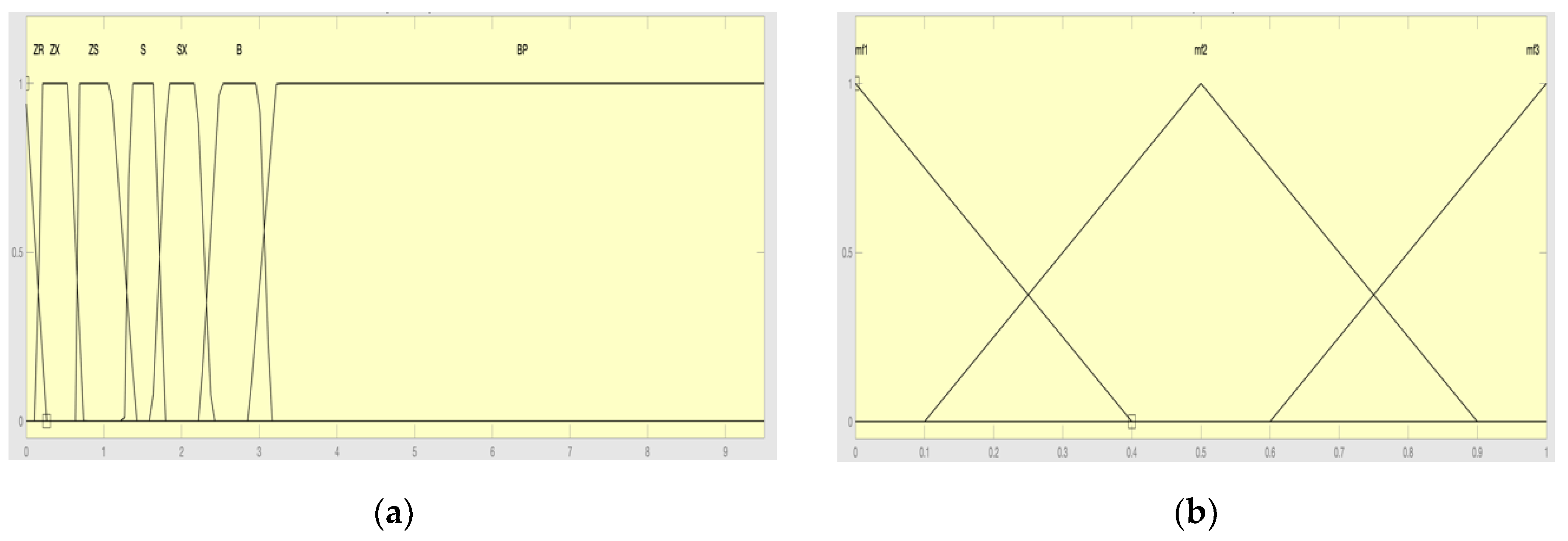
3.2.1. Selection of Input and Output Variables

The fuel cell hybrid vehicle (FCHV) is selected in this paper, so the fuel cell and battery should be considered in power distribution. Therefore, the FCHV required power is selected as an input variable p, and another input variable is the battery SOC. And one output variable K which represents the ratio of the output power of the fuel cell to the required power. The fuzzy field scope of the vehicle required power is set as [0,95,000], the fuzzy field scope of SOC is set as [0,1], and the fuzzy field scope of output variable is set as [0,1.6].

3.2.2. Fuzzy Field Scope

The fuzzy subset of p is divided into seven fuzzy sets: ZR (zero), ZX (negatively small), ZS (small), S (positively small), SX (medium), B (big), and BP (positively big), the fuzzy subset of SOC is classified into three fuzzy sets: L (low), M (medium), and H (high), the fuzzy subset of K is fuzzified into {0, 0.3, 0.4, 0.5, 0.6, 0.7, 0.8, 1.1, 1.2, 1.3, 1.4, 1.5, 1.6}. These values are obtained by identification method based on literature review and a large amount of input and output test data [26,27,28]. Heterogeneous distribution subject function is selected as the membership function of FLC. It can improve the sensitivity of fuzzy control. The membership functions of input variables are shown in Figure 1.

3.2.3. Fuzzy Reasoning Rules

The dynamic and economic performance of automobile is paid much more attention to by consumers. The FLC strategy designed in this paper should meet the following design requirements:
(1)
The sum of the power provided by the fuel cell and the battery must meet the bus required power.
(2)
The battery can always work in the ideal working area that SOC is between 0.6 and 0.8, and the fuel cell can work in the efficient area that the efficiency is more than 40%.
(3)
The equivalent fuel consumption of fuel cell is reduced, and the economic performance of the vehicle is improved.
According to the above requirements, the required fuzzy rule base is developed, as shown in Table 3.

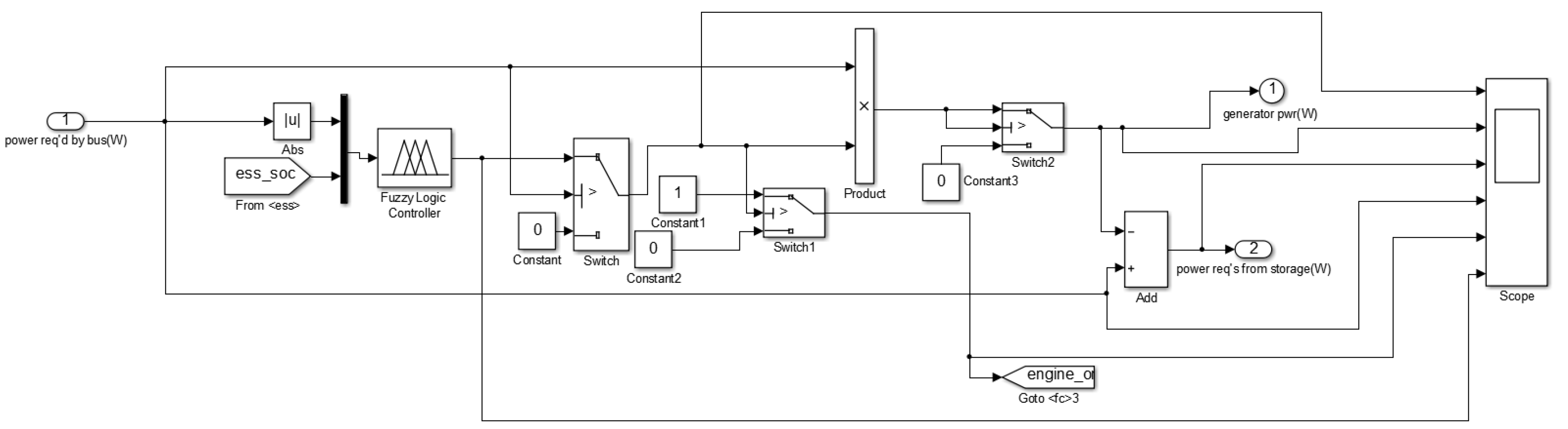
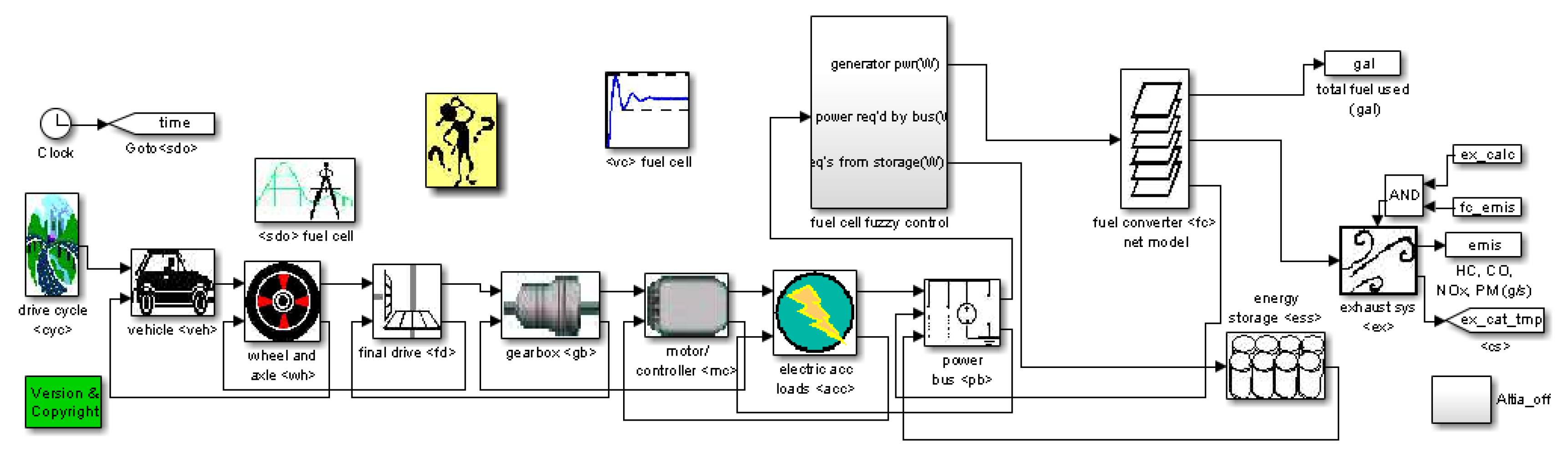
4. FCHV Modelling and Simulation

The designed energy management system (EMS) based on FLC under the environment of Matlab/Simulink is adopted as Figure 2 shown. This model was embedded to replace PFC. The block diagram of the whole vehicle equipped with FC, battery and so on is shown as Figure 3.

Simulation Parameters

Different drive cycles require different output power of the motor. In view of the large number of cars in China and the increasing number of cars in county cities, it is necessary to establish a suitable driving cycle condition. In consideration of this reality in China, this paper introduces Chinese Typical City Driving Cycle.
However, to study the performance of FCHV that uses FLC strategy, instead of specified cycle, the tests are done under four different cycles. Chinese Typical City Driving Cycle (China), Economic Commission for Europe and Extra Urban Driving Cycle (ECE+EUDC), Urban Dynamometer Driving Schedule (UDDS), and New Europe Driving Cycle (NEDC) are chosen as four driving cycle for comprehensively evaluating the vehicle performance. The main parameters are shown in Table 4.

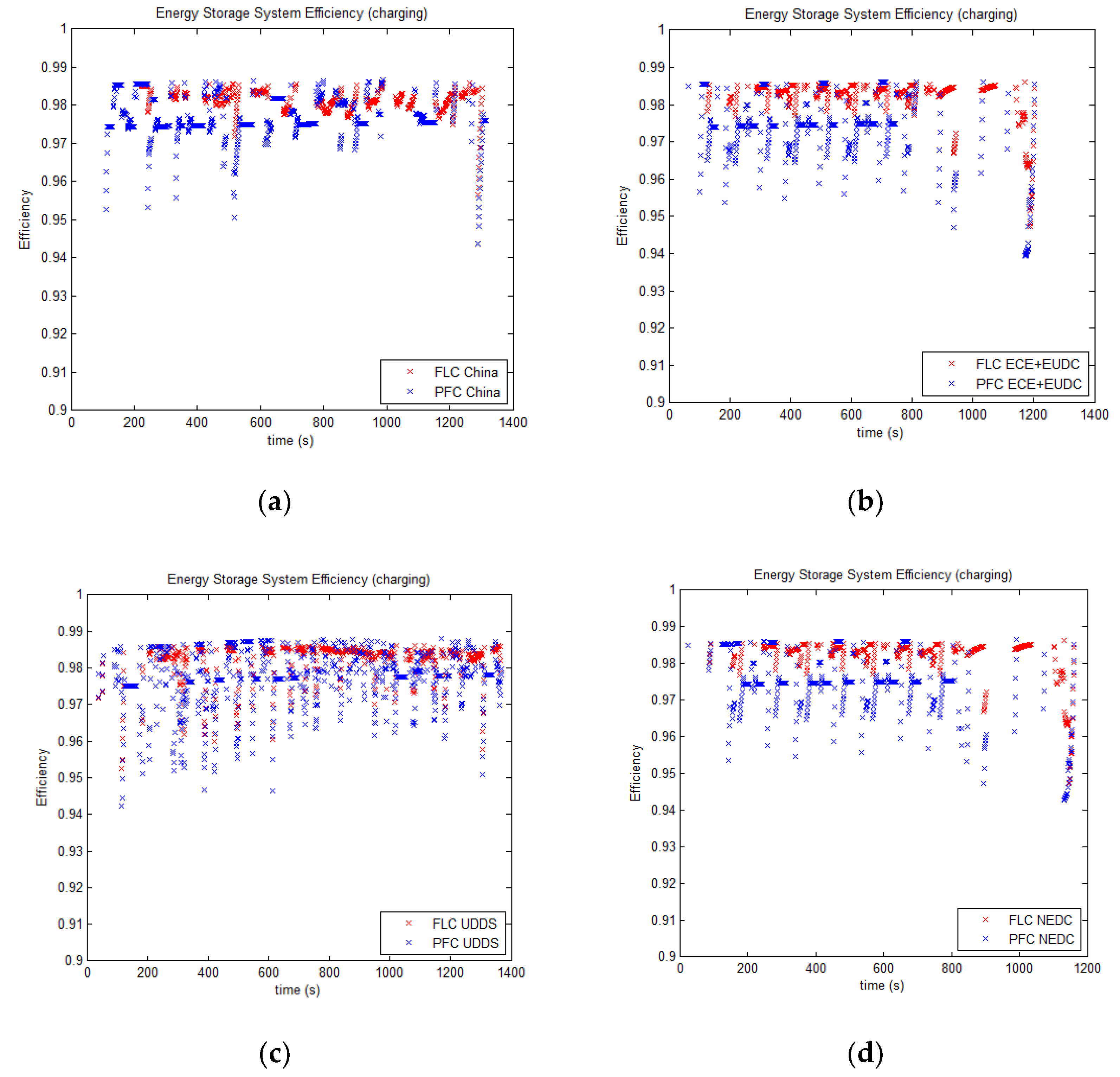
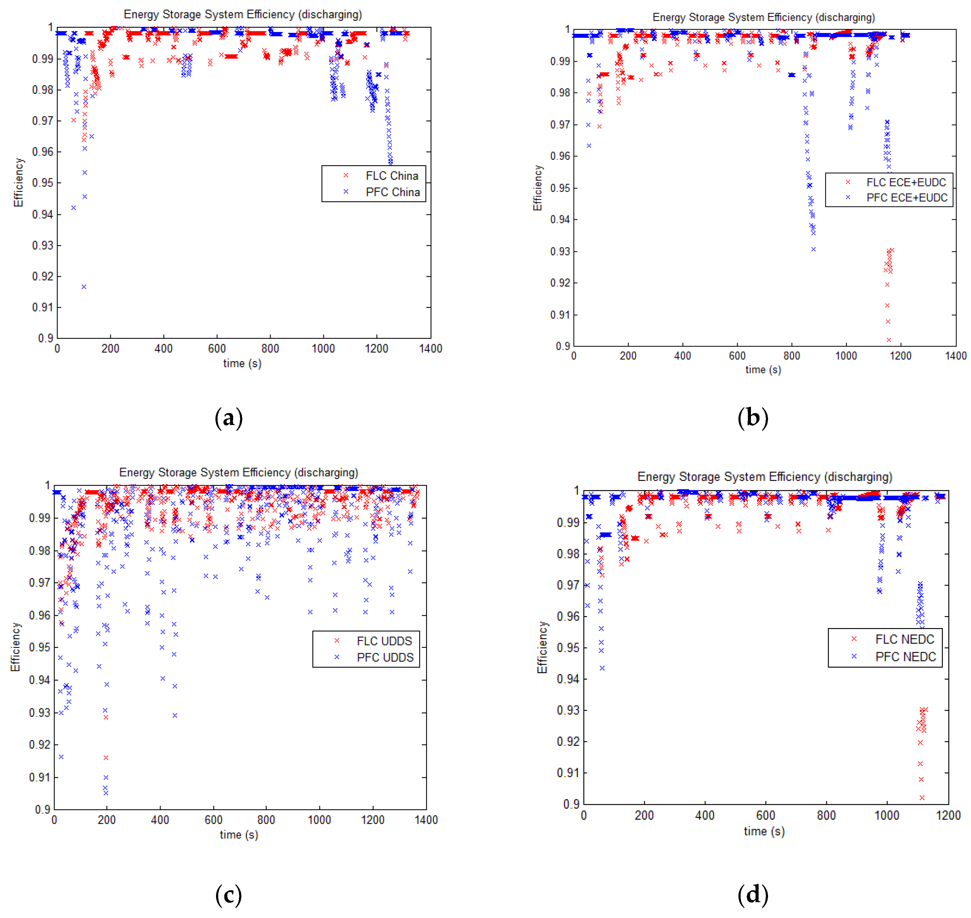
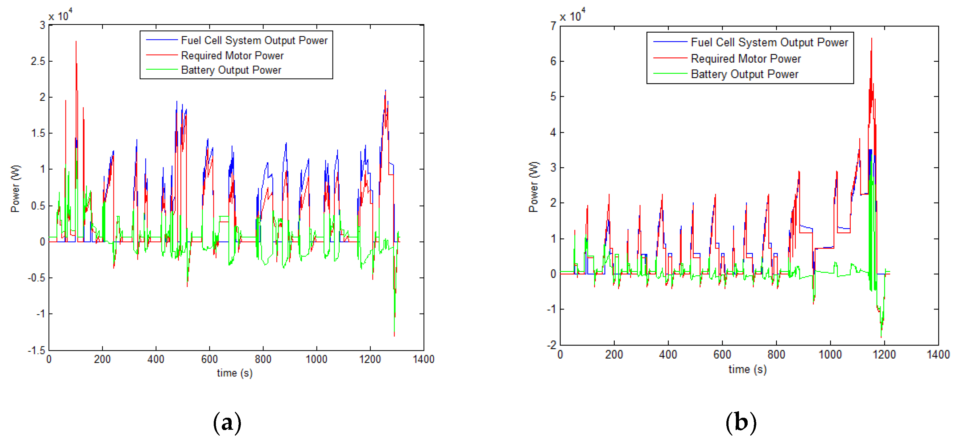
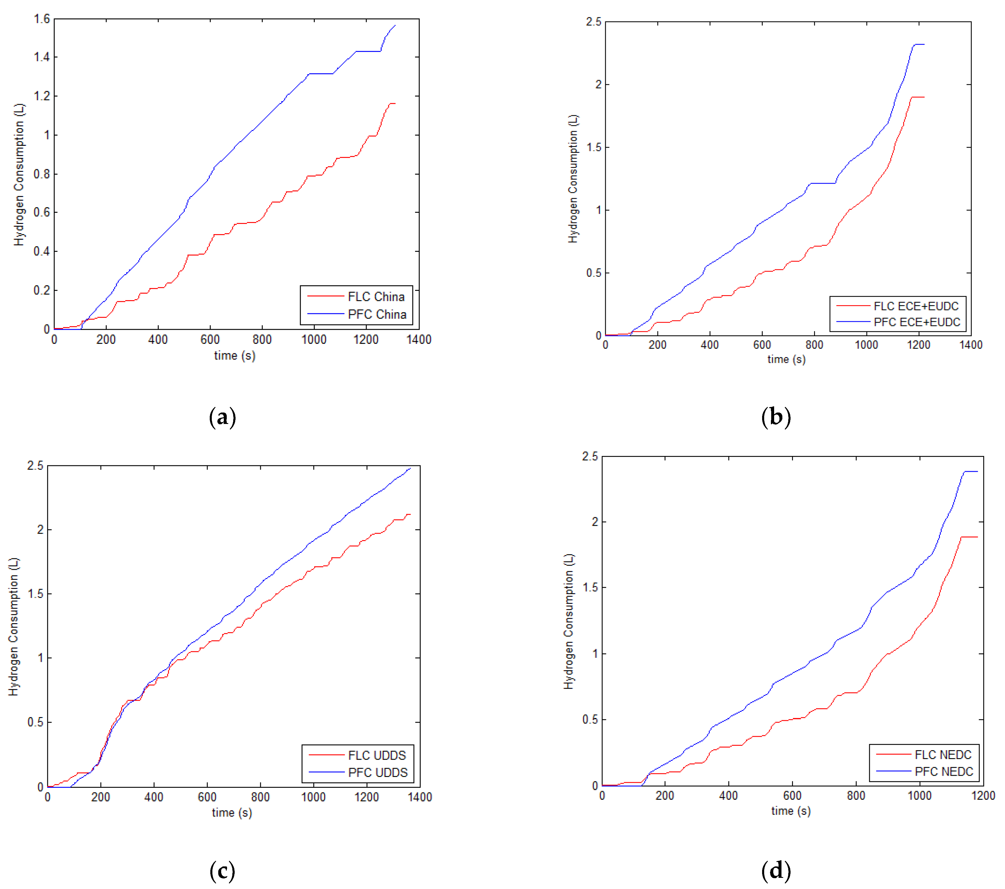
5. Results and Discussion

In order to compare the indexes of acceleration tests, economy and grade, Chinese Typical City Driving Cycle is selected. The simulation results of PFC strategy and FLC strategy are compared and analyzed. Table 5 compares the dynamic and economic performance of FCHV.
According to Table 5, the dynamic and economic performance of PFC strategy and FLC strategy can satisfy the design requirements. From the perspective of dynamic performance, the maximum speed of FCHV using the FLC strategy can reach 157.3 km/h, slightly higher than that of the original PFC strategy. The acceleration time of 0–50 km/h and 0–100 km/h decreased by 9% and 17%, respectively. The maximum gradeability at 30 km/h was reduced by 8%. In view of the economic performance, hydrogen consumption and the equivalent oil consumption of FCHV utilizing FLC strategy is respectively 74.1 L/100 km and 5 L/100 km. Compared with the vehicle that uses PFC strategy, hydrogen consumption and the equivalent gasoline consumption reduces 6.9% and 9.1% respectively. Obviously, FCHV becomes more economical.
According to Table 6, fuel economy, FCS/battery efficiency and SOC are the main targets that should be studied. It’s obvious that the FLC for FCHV has lower hydrogen consumption and equivalent energy than PFC. Therefore, the proposed FLC strategy not only satisfies the requirement of FCHV, but also improves the economic performance. And the efficiency of FLC for FCHV is higher than that of PFC in terms of fuel cell system and battery. Moreover, as a significant index of FCHV, the SOC of the battery is more stable.
Comparison of SOC in two different strategies are shown in Figure 4. It can be seen from the curve that fluctuation range of both strategies is in good charging and discharging area. In comparison, the variation range of SOC using PFC strategy is relatively larger, while utilizing FLC strategy is more stable and belongs to the type of shallow charge and shallow discharge, which effectively improves the battery life and decreases the cost of vehicle maintenance that is the most critical issue of people’s concern.
Figure 5 and Figure 6 show the efficiency curves of charging and discharging components in different strategies. Through the comparison of working efficiency points, it can be clearly seen that the charging and discharging efficiency points of FLC strategy are more concentrated. As can be seen from Table 6, efficiency of FCS and battery under FLC strategy is higher. Since the extremely high cost of FC, the improvement of efficiency is of great significance. Through a thorough comparison, the increase in economic performance and operating efficiency of FCHV indicates the priority of FLC strategy.
As shown in Figure 7, when FLC strategy is utilized, the initial SOC of the battery is 0.7 and the battery can provide enough power for the motor during the startup. After a short time, the fuel cell comes into operation and charges the battery. Therefore, the working life of battery is improved and the external battery charger is not required. In order to ensure that the fuel cell can work in the efficient zone, fuel cell and battery rarely output the power together. Figure 8 shows hydrogen consumption in four cycle conditions. It’s clear that the hydrogen consumption of FLC for FCHV is lower. Therefore, this strategy has a better performance in terms of fuel economy.

6. Conclusions

In this paper, the powertrain of an FCHV is designed and the parameter of the main components obtained. The simulation software ADVISOR is secondly developed and a Chinese typical city driving cycle is introduced. Since energy management strategy plays a vital role in vehicle performance, the FLC strategy and PFC strategy are designed for the studied FCHV.
Both PFC and the proposed FLC strategy can meet the requirement of dynamic performance of the studied FCHV. Moreover, fuel economy, efficiency of power supplies, battery SOC and battery life are some significant outcomes achieved by the FLC strategy. In four driving cycles, the FLC for FCHV has lower consumption and higher efficiency than that of the PFC strategy. Hence, in terms of economy and operating efficiency, the FLC strategy is better. Furthermore, the charging and discharging efficiency under the FLC strategy is more stable and the SOC under the FLC strategy is smoother than that of the PFC strategy. Therefore, the battery life can be extended and the cost of vehicle maintenance can be decreased. When FLC strategy is utilized, the battery can provide enough power for the motor during the startup and the fuel cell comes into operation and charges the battery after a short time. Since the battery is continuously charged during the driving cycles, there is no need to provide an external battery charger.
The FLC strategy is more suitable for the energy management strategy for fuel cell and battery hybrid vehicles. Research results and proposed FLC strategy can be referenced for further such researches.

Author Contributions

All of the authors contributed to publishing this article. The collection of materials and summarization of this article was done by D.L. and B.X. The simulation and analysis were done by D.L. and B.X. The conceptual ideas, methodology and guidance for the research were provided by Z.M. and J.T. All authors have read and agreed to the published version of the manuscript.

Funding

We gratefully acknowledge the financial support of the National Natural Science Foundation of China (No. 51306079 and 51176069), the Jiangsu Provincial Key Research and Development Program (No. BE2017008) and Scientific Research Foundation of Nanjing Forestry University (No. GXL2018004).

Conflicts of Interest

The authors declare no conflicts of interest.

References

  1. Guenther, M.B. Modelling and Design Optimization of Low Speed Fuel Cell Hybrid Electric Vehicles. Master’s Thesis, University of Victoria, Victoria, BA, Canada, 2005. [Google Scholar]
  2. Montazeri-Gh, M.; Mahmoodi-k, M. Development a new power management strategy for power split hybrid electric vehicles. Transp. Res. Part D Transp. Environ. 2015, 37, 79–96. [Google Scholar] [CrossRef]
  3. Djerioui, A. Energy management strategy of Supercapacitor/Fuel Cell energy storage devices for vehicle applications. Int. J. Hydrogen Energy 2019, 44, 23416–23428. [Google Scholar] [CrossRef]
  4. Hong, Z.H.; Zhu, Y.N.; Shang, W.L.; Li, Q.; Chen, W.E. Research of energy management strategy for Fuel Cell/Battery hybrid locomotive. In Proceedings of the 2017 IEEE Transportation Electrification Conference and Expo, Asia-Pacific (Itec Asia-Pacific), Harbin, China, 7–10 August 2017; pp. 546–550. [Google Scholar]
  5. Chen, Z.; Guo, N.Y.; Zhang, Q.; Shen, J.W.; Xiao, R.X. An optimized rule based energy management strategy for a Fuel Cell/Battery vehicle. In Proceedings of the IEEE Vehicle Power and Propulsion Conference (Vppc), Belfort, France, 11–14 December 2017. [Google Scholar]
  6. Carignano, M.G.; Costa-Castello, R.; Roda, V.; Nigro, N.; Junco, S.; Feroldi, D. Energy management strategy for fuel cell-supercapacitor hybrid vehicles based on prediction of energy demand. J. Power Sources 2017, 360, 419–433. [Google Scholar] [CrossRef] [Green Version]
  7. Xu, L.F. Application of Pontryagin’s Minimal Principle to the energy management strategy of plugin fuel cell electric vehicles. Int. J. Hydrogen Energy 2013, 38, 10104–10115. [Google Scholar] [CrossRef]
  8. Bendjedia, B.; Rizoug, N.; Boukhnifer, M.; Bouchafaa, F. Improved energy management strategy for a hybrid fuel cell/battery system Simulation and experimental results. COMPEL 2017, 36, 1008–1027. [Google Scholar] [CrossRef]
  9. Aouzellag, H.; Ghedamsi, K.; Aouzellag, D. Energy management and fault tolerant control strategies for fuel cell/ultra-capacitor hybrid electric vehicles to enhance autonomy, efficiency and life-time of the fuel cell system. Int. J. Hydrogen Energy 2015, 40, 7204–7213. [Google Scholar] [CrossRef]
  10. Lü, X.Q.; Wu, Y.B.; Lian, J. Energy management of hybrid electric vehicles: A review of energy optimization of fuel cell hybrid power system based on genetic algorithm. Energy Convers. Manag. 2020, 205, 112474. [Google Scholar] [CrossRef]
  11. Song, K.; Wang, X.D.; Li, F.Q. Pontryagin’s minimum principle-based real-time energy management strategy for fuel cell hybrid electric vehicle considering both fuel economy and power source durability. Energy 2020, 205, 118064. [Google Scholar] [CrossRef]
  12. Li, X.Y.; Wang, Y.J.; Yang, D.; Chen, Z.H. Adaptive energy management strategy for fuel cell/battery hybrid vehicles using Pontryagin’s Minimal Principle. J. Power Sources 2019, 440, 227105. [Google Scholar] [CrossRef]
  13. Fu, Z.N.; Li, Z.H.; Si, P.J.; Tao, F.Z. A hierarchical energy management strategy for fuel cell/battery/supercapacitor hybrid electric vehicles. Int. J. Hydrogen Energy 2019, 44, 22159–22416. [Google Scholar] [CrossRef]
  14. Odeim, F.; Roes, J.; Heinzal, A. Power management optimization of a fuel cell/battery/supercapacitor hybrid system for transmit bus applications. IEEE Transp. Veh. Technol. 2016, 65, 5783–5788. [Google Scholar] [CrossRef]
  15. Hu, Z.Y.; Li, J.Q.; Xu, L.F. Muti-objective energy management optimization and parameter sizing proton exchange membrane hybrid fuel cell vehicles. Energy Convers. Manag. 2016, 129, 108–121. [Google Scholar] [CrossRef]
  16. Zhang, W.B.; Li, J.Q.; Xu, L.F. Optimization for a fuel cell/battery/capacity tram with equivalent consumption minimization strategy. Energy Convers. Manag. 2017, 134, 59–69. [Google Scholar] [CrossRef]
  17. Kim, M.; Sohn, Y.J.; Lee, W.Y.; Kim, C.S. Fuzzy control based on engine sizing optimization for a fuel cell/battery hybrid mini-bus. J. Power Sources 2008, 178, 706–710. [Google Scholar] [CrossRef]
  18. Li, Q.; Chen, W.R.; Li, Y.K.; Liu, S.K.; Huang, J. Energy management strategy for fuel cell/battery/ultracapacitor hybrid vehicle based on fuzzy logic. Int. J. Electr. Power Energy Syst. 2012, 43, 514–525. [Google Scholar] [CrossRef]
  19. Zhang, G.R.; Chen, W.R.; Li, Q. Modeling, optimization and control of a FC/battery hybrid locomotive based on ADVISOR. Int. J. Hydrogen Energy 2017, 42, 18568–18583. [Google Scholar] [CrossRef]
  20. Chen, J.; Xu, C.F.; Wu, C.S. Adaptive fuzzy logic control of fuel-cell-battery hybrid systems for electric vehicles. IEEE Trans. Ind. Inform. 2018, 14, 292–300. [Google Scholar] [CrossRef]
  21. Ahmadi, S.; Bathaee, S.M.T.; Hosseinpour, A.H. Improving fuel economy and performance of a fuel-cell hybrid electric vehicle (fuel-cell, battery, and ultra-capacitor) using optimized energy management strategy. Energy Convers. Manag. 2018, 160, 74–84. [Google Scholar] [CrossRef]
  22. Fu, Z.M.; Zhu, L.L.; Tao, F.Z.; Si, J.P.; Sun, L.F. Optimization based energy management strategy for fuel cell/battery/ultracapacitor hybrid vehicle considering fuel economy and fuel cell lifespan. Int. J. Hydrogen Energy 2020, 45, 8875–8886. [Google Scholar] [CrossRef]
  23. Nymand, M.; Andersen, M.A. High-efficiency isolated boost DCDC converter for high-power low-voltage fuel-cell applications. IEEE Trans. Ind. Electron. 2010, 57, 505–514. [Google Scholar] [CrossRef] [Green Version]
  24. Tu, X. Research on Design and Optimization of Power System of Fuel Cell/Battery Hybrid Vehicle. Master’s Thesis, Chongqing Jiaotong University, Chongqing, China, 2013. [Google Scholar]
  25. Triche, E.J.; Beno, J.H.; Tims, H.E. Shock loading experiments and requirements for electric wheel motors military vehicles. SAE Tech. Pap. 2005, 0261–0278. [Google Scholar] [CrossRef]
  26. Tanaka, K. A sum of squares approach modeling and control of nonlinear dynamical systems with polynomial fuzzy systems. IEEE Trans. Fuzzy Syst. 2009, 04, 911–920. [Google Scholar] [CrossRef]
  27. Amirabadi, M.; Farhangi, S. Fuzzy control of hybrid fuel cell/battery power source in electric vehicle. In Proceedings of the IEEE Conference on Industrial Electronics and Applications, Singapore, 24–26 May 2006; pp. 1–3. [Google Scholar]
  28. Zhang, D.H.; Zhou, J.Y.; Su, Y.X. Research of regenerative braking energy recovery of HEV based on fuzzy logic. J. Wuhan Univ. Technol. 2011, 33, 717–720. [Google Scholar]
Figure 1. Membership functions of input variables: (a) fuzzy subset of p and (b) fuzzy subset of SOC.
Processes 08 00882 g001
Figure 2. Proposed fuzzy logic control.
Processes 08 00882 g002
Figure 3. Simulation model of the vehicle.
Processes 08 00882 g003
Figure 4. SOC in different driving cycles. (a) Chinese Typical City Driving Cycle (China), (b) Economic Commission for Europe and Extra Urban Driving Cycle (ECE+EUDC), (c) Urban Dynamometer Driving Schedule (UDDS), and (d) New Europe Driving Cycle (NEDC).
Processes 08 00882 g004
Figure 5. Energy storage system efficiency of charging: (a) China, (b) ECE+EUDC, (c) UDDS, and (d) NEDC.
Processes 08 00882 g005
Figure 6. Energy storage system efficiency of discharging: (a) China, (b) ECE+EUDC, (c)UDDS, and (d) NEDC.
Processes 08 00882 g006
Figure 7. Power curves of afuel cell hybrid vehicle (FCHV): (a) China, (b) ECE+EUDC, (c) UDDS, and (d) NEDC.
Processes 08 00882 g007aProcesses 08 00882 g007b
Figure 8. Comparisons of hydrogen consumption: (a) China, (b) ECE+EUDC, (c) UDDS, and (d) NEDC.
Processes 08 00882 g008
Table 1. Main vehicle parameters and design goals.
Vehicle ParametersValueDesign GoalsValue
Mass (kg)1800Maximum gradeability at 30 km/h (%)≥30
Coefficient of air resistance0.31Maximum speed (km/h)≥150
Coefficient of rolling resistance0.0160–50 km/h acceleration time (s)≤8
Frontal area (m2)2.680–100 km/h acceleration time (s)≤15
Wheelbase (m)2.67Equivalent oil consumption (L/100 km)6
Wheel rolling radius (m)0.35
Table 2. Parameters of motor, fuel cell and battery.
Motor
Rated power (kW)30Maximum power (kW)95
Rated speed (r/min)4800Maximum speed (r/min)11,500
Rated torque (n·m)80Maximum torque (n·m)210
Fuel cell
TypePEMFCRated power (kW)35
Battery
TypeLithium-ionNumber85
Rated capacity (Ah)6Capacity (Ah)≥8.0
Maximum discharge rate30CRated voltage (V)3.8
Table 3. Fuzzy logic control (FLC) rule base.
SOCp
ZRZXZSSSXBBP
L1.61.51.41.31.21.11.1
M000.30.40.40.40.6
H0000.30.40.60.7
Table 4. Parameters of driving cycle.
ParametersChinaECE+EUDCUDDSNEDC
Time (s)1314122513691184
Distance (km)5.9410.9311.9910.93
Average speed (km/h)16.2732.1031.5133.21
Maximum speed (km/h)60.3512091.25120
Average acceleration (m/s2)0.300.540.500.54
Average deceleration (m/s2)−0.43−0.79−0.58−0.79
Maximum acceleration (m/s2)0.921.061.481.06
Maximum deceleration (m/s2)−1.05−1.39−1.48−1.39
Idle time (s)381339259298
Number of stop14131713
Grade (%)0000
Table 5. Test results of dynamic and economic characteristics.
Dynamic PropertyPFCFLCDesign Goal
0–50 km/h Acceleration time (s)44.48
0–100 km/h Acceleration time (s)11.113.515
Maximum speed (km/h)156.8157.3150
Maximum gradeability at 30 km/h (%)403230
Economic Property
Hydrogen consumption (L/100 km)79.674.1
Gasoline equivalent (L/100 km)5.55.06
Table 6. Simulation results for different driving cycles.
CycleParameterPFCFLC
ChinaHydrogen consumption (L/100 km)79.674.1
Gasoline equivalent (L/100 km)5.55.0
Eff_FCS52.5453.26
Eff_Bat96.1597.45
SOC0.08−0.03
ECE+EUDCHydrogen consumption (L/100 km)70.465.8
Gasoline equivalent (L/100 km)4.84.5
Eff_FCS55.5455.78
Eff_Bat95.3295.48
SOC0.07−0.04
UDDSHydrogen consumption (L/100 km)71.666.9
Gasoline equivalent (L/100 km)4.84.5
Eff_FCS56.2256.92
Eff_Bat95.1696.53
SOC0.06−0.03
NEDCHydrogen consumption (L/100 km)7165.4
Gasoline equivalent (L/100 km)4.84.4
Eff_FCS54.6155.32
Eff_Bat95.4495.87
SOC0.09−0.04
Eff_FCS: Fuel cell system average efficiency. Eff_Bat: Battery average efficiency SOC: The difference between final and initial SOC.

