Article

The Neural Network Revamping the Process’s Reliability in Deep Lean via Internet of Things

1
Department of Industrial Engineering, Zagazig University, Zagazig 44519, Egypt
2
Department of Industrial and Systems Engineering, College of Engineering, Princess Nourah Bint Abdulrahman University, Riyadh 84428, Saudi Arabia
3
Department of Industrial Engineering, Alexandria Higher Institute of Engineering and Technology (AIET), Alex 21311, Egypt
4
Department of Computer and Systems Engineering, Zagazig University, Zagazig 44519, Egypt
5
Department of Computer Sciences, College of Computer and Information Sciences, Princess Nourah Bint Abdulrahman University, Riyadh 84428, Saudi Arabia
*
Author to whom correspondence should be addressed.
Processes 2020, 8(6), 729; https://doi.org/10.3390/pr8060729
Submission received: 12 May 2020 / Revised: 14 June 2020 / Accepted: 15 June 2020 / Published: 23 June 2020

Abstract

:
Deep lean is a novel approach that is concerned with the profound analysis for waste’s behavior at hidden layers in manufacturing processes to enhance processes’ reliability level at the upstream. Ideal Standard Co. for bathtubs suffered from defects and cost losses in the spraying section, due to differences in the painting cover thickness due to bubbles, caused by eddies, which move toward the bathtubs through hoses. These bubbles and their movement are considered as a form of lean’s waste. The spraying liquid inside the tanks and hoses must move with uniform velocity, viscosity, pressure, feed rate and suitable Reynolds circulation values to eliminate the eddy causes. These factors are tackled through the adoption Internet of Things (IoT) technologies that are aided by neural networks (NN) when an abnormal flow rate is detected using sensor data in real-time that can reduce the defects. The NN aimed at forecasting eddies’ movement lines that carry bubbles and works on being blasted before entering the hoses through using Design of Experiment (DOE). This paper illustrates a deep lean perspective as driven by the define, measure, analysis, improvement and control (DMAIC) methodology to improve reliability. The eddy moves downstream slowly with an anti-clockwise flow for some of the optimal values for the influencing factors, whereas the circulation of Ω increases, whether for vertical or horizontal travel.

1. Introduction

In recent years, great interest has emerged in the use of deep learning, especially for tackling problems at the sub-cause level, as the lean approach recommends [1]. The convolutional neural network (CNN) has become well-known among various types of deep analyses since its results first appeared in the Image Net Large Scale Visual Recognition Competition (ILSVRC) in 2012 [2,3]. The deep lean emulated by deep learning provides the opportunity to analyse the data regarding the sub-causes to improve the analysis and control phases in the define, measure, analysis, improvement and control (DMAIC) methodology, and create the new perception of “deep lean”, which is important for providing an interdisciplinary overview for tackling various challenges of manufacturing processes, such as productivity, environmental impact, reliability and sustainability [4,5]. Maria Joao Félix et al., 2019 [6], contributed to finding an innovative approach to simplifies, enhances and improves the reliability level of mechanical processes. The result is that processes will have a high reliability level, which will contribute to lower the defects and losses. Society and technology are evolving and the outputs’ quality level has a top priority in the improvement agenda, so there is the need to reach a smart design that reduces the lack of processes’ performance. These ideas elevate the design challenges to a new dimension of controlling as a poka-yoke recommended by M. Rükmann et al., 2015 [7]. The current study focuses on processes’ improvement, viewing the resolution of the fluid mixture movement for the spraying process, which is one of six main processes of bathtubs production, while coating the bathtubs, seeking to demonstrate the ability of a spraying device in the improvement of processes’ outputs in a way to solve the problems, managing to create a correct balance between the productivity goals, product and user, as claimed by G. Ringen et al., 2018 [8]. The spraying process is one of the main processes used for multiple industries such as automotive, surfaces painting and kids’ toys, among others.
Emerging ICT technologies relevant for understanding manufacturing sub-processes via sensing problems upstream from the waste’s occurrence [9] using the Internet of Things (IoT) to detect defects and enable rapid decision making for continuing or stopping the process [10], cloud computing [11] and big data analysis [12,13] and offer the abilities to tackle the minor details to revamp a lean concept to become deep lean. The traditional lean philosophy aimed at eliminating the famous eight forms of waste in the visible manufacturing processes layer caused by one of eight fish-bone skeleton causes (4′M, 2′P, 2′E), which is considered as a seed of improvement for process reliability as claimed by M. Gregor (2017) [14], via simulation tackling. The disturbance of paint’s liquid during its movement trip between the upstream station (paint’s tank) and its downstream destination (the spraying hoses) is widespread in processes for stressors due to the uncontrolled of influencing factors [15].
In contrast, deep lean is implemented into invisible layers, such as data transfer, data store, equipment over-processing or use, and so on, in which the lean waste can be seen according to another deeper point of view. The fish-bone is transformed into a Pareto chart, which illustrates the cumulative weights of every sub-cause in descending order [16]. This study aimed at monitoring the “eddy bursting” occurrences that have maximum movement of waste, to indicate the sudden disorganization of a slim swirl that occurs when the characteristic ratio of azimuthal to axial velocity components is varied in a common manufacturing sector, which is “painting” [17,18]. The axial flow slope designates an internal stagnancy point on the vortex/eddy axis, followed by backward flow in an area of limited axial extent [19]. The possibility of collapse is a characteristic behavior of eddy cores. Within many eddy flows, a core of high vortices can be found that is almost minimal at the symmetric axis. There is a characteristically ratable axial component of movement in the increments of the eddy, or azimuthal component. Such an eddy pulp core is easily nominated by crossing a fluid via a hosepipe and picking up the eddy with a set of vanes at the entrance. The original sin is of critical importance in various devices of technological significance, like delta wings (aircraft) [20,21,22], the draft hose of hydraulic turbines [23,24] and swirling combustors [16,25]. Similarly, Aksel and Kaya [26] and Jochmann et al. [27] carried out numerical computations of the eddy collapsing phenomenon in a cylinder section. Under controlled phenomenon circumstances, experiments on vortices confined in hoses were devised by R. Ruith et. al., 2003 [28] and Abed and Farag [17], and many others. Most investigators used a horizontal divergent hose as a test section to study the different shapes of the eddy collapse phenomena. In previous studies, the hose length was fixed, there was a steady diameter for the vertical cylindrical hose which was not changed and some of them used only one direction of flow. Moreover, despite empirical, numeral and theoretical research, the vortex waste, that builds on its frame, which leftover a debatable and commonly rejected caption has stood out. The goal of the sitting realization is to research the reliance of the core eddy disruption shapes. The resultant waste was on some of the influencing factors (including flow rate, feed rate, pressure, viscosity, nozzle diameter, liquid temperature, Reynolds number (Re) and circulation number (Ω)) in both a vertical and horizontal cylindrical hose with a fixed diameter, for two hose lengths (of Lv = 40 cm and Lh = 150 cm/Ø 0.6″), as well as for an anti-clockwise flow direction. A mixture liquid was used as the working fluid and the flow visualization technique used was dye injection.
The fluid mechanism movement is subject to random disturbances and has pushed researchers to evolve their monitoring from a 2D, which is based on monocular vision, to a 3D analysis via a binocular stereovision [29]. This work-based analysis on two cameras, GS3-U-123s6m, offers a 4096 × 3000-pixel resolution at a maximum speed of 28 frames per second to achieve 3.45 μm resolutions per 1pixel. Three-dimensional monitoring requires identifying the intersection of two optical rays formulated in a gradual coordinate system, which is calibrated with a special target that undergoes arbitrary motions for resulting bubbles [30]. This work aims at controlling deployed bubbles via monitoring and chases them to achieve burst, through evolving the sensors of the proposed device to control some of the significant factors, which maintain the match stationary case for spraying liquids [31]. It is vital to understand the characteristics of the studied liquid to allow for discovering the possible reanimation defects in shape for the crucial error types. This work investigates and analyzes the resulting bubbles’ geometric errors (i.e., liquid characteristic waste). Therefore, this work resorts to deep imaging for the studied liquid to monitor the resulting waste such as the bubbles and monitor its movement to eliminate it before reaches to hoses.
Accurate prediction of such failures in the existence of the Internet of Things (IoT) technologies using sensor data in real-time that can reduce the defects. Deep Learning (DL) algorithms useful in predicting the equipment function failure. Srikanth Namuduri et al., 2019 [32] review the DL algorithms used for predictive maintenance and presents a case study of engine failure prediction. This paper discusses the current use of sensors that aided with neural networks in the industry and future opportunities for electrochemical sensors in predictive performance for a specific process and presents a case study in an international firm for bathtubs.

2. Main Objective

The factory aims to achieve its maximum productivity in 2019, up to 93–98%, via competitiveness in reducing the defective outputs, with monetary saving value. The proposed flowchart mentioned in Figure 1A clarifies the sequential stages of tackling the problem through a DMIAC roadmap to eliminate the movement of undesirable waste using the Deep-lean level algorithm via imaging [33]. While Figure 1B describes the relation between IoT and other tools used to accurate its results via DMAIC phases. The paper concentrates on highlighting the integration of NN with the IoT. The IoT considered a database saves many big data for specific processes to support the NN in its forecasting process with minimum errors to draw the preferred eddy’s paths to face it and eliminate.

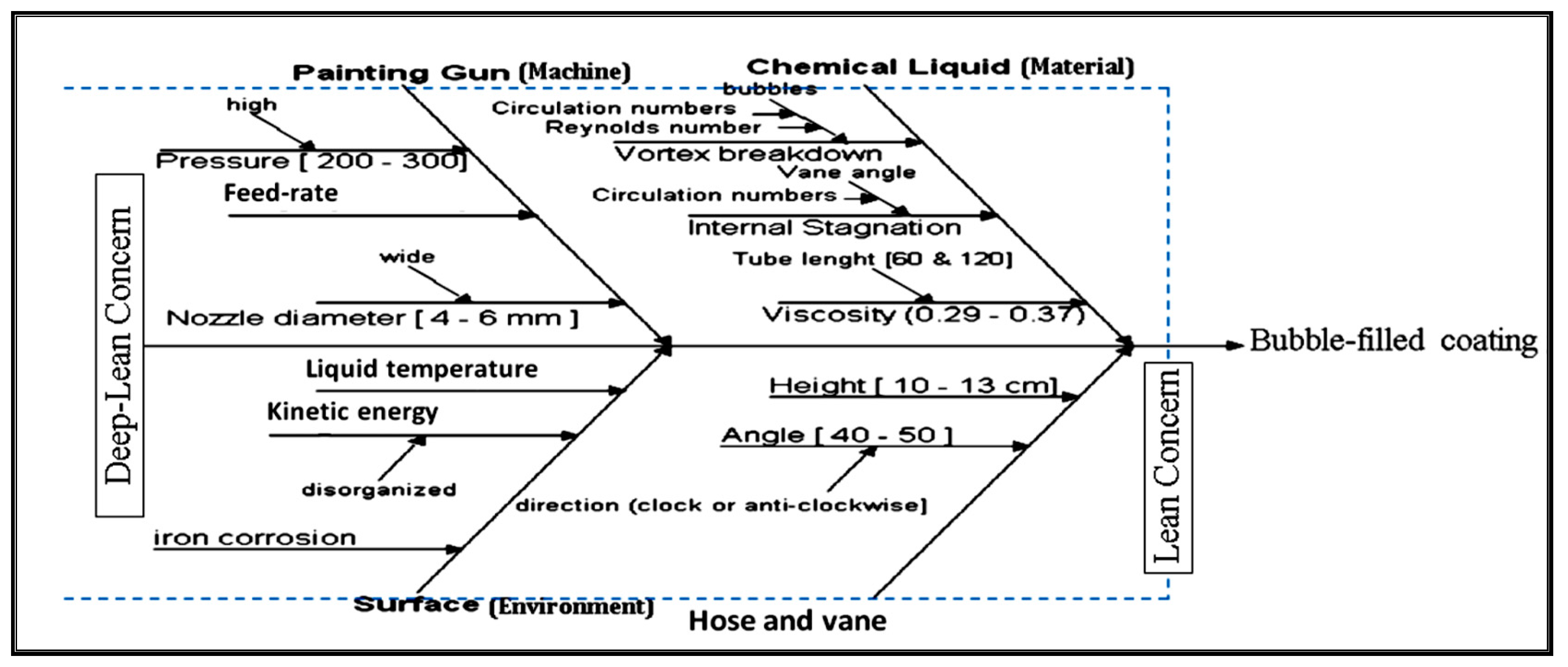
3. The “Define” Phase (DOE Setup and Test Procedures)

A.G. Arteaga (2019) [33] advocated mass quality customization based on flexible manufacturing processes [34]. Flexibility makes resource utilization, rate of production, and cost subject to experimentation and analysis based on performance indicators. A.G. Arteaga (2019) also reported conditions of a push/pull system (i.e., Kanban) used to control bubbles distributed throughout layers of a liquid due to its circulation, where the bubbles affected the output quality.
The objectives of this experimental work were to study the effects of interaction between significant factors relating to the chemical liquid used to coat bathtub surfaces and eddies created that cause bubbles therein, and to study their direction of movement (e.g., downstream) during motion through the hoses. Figure 2 illustrates the “cause and effect” diagram for coat thickness that suffers shrinkage due to eddy effects (i.e., bubbles), which are created due to disturbance of the chemical coating while it is being distributed. This problem causes downtime of more than 18,400 s/week, which represents 70 bathtubs scrapped/week. Bubbles are created and move undesirable distances, and must be minimized to avoid producing defective bathtubs. Thus, the process must be controlled, as illustrated in Figure 3, and the significant factors must be analyzed to determine which are significant, as illustrated in Figure 4, Figure 5 and Figure 6.

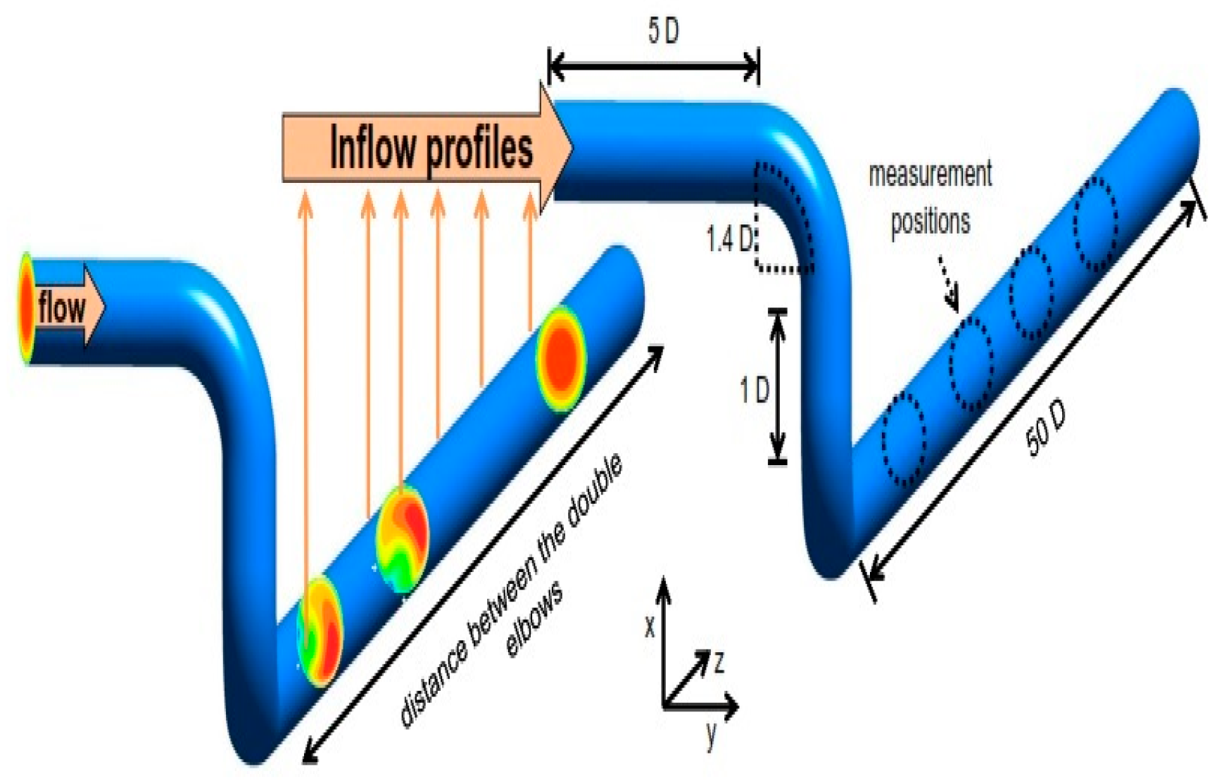
4. Measurement Phase (Device Description)

This phase is based on waste detection, which is a core aspect of lean philosophy wherein the waste is identified prior to its elimination. Therefore, the researcher’s purpose is to detect the waste, via waste-detection classification, and identify its effect. However, it is considered difficult to apply this phase in manufacturing where processes are based on concealed or deep areas such as the mixed liquid tank, and while high variability occurs from one form of waste to another due to process characteristics [35]. Lean processes involve layers of implementation to eliminate waste using many ideas and algorithms. This work highlighted the potential of implementing deep-lean thinking in hidden layers of processes with the assistance of imaging techniques, as Reference [36] recommended, detecting waste in order to improve the robustness of waste detection in industrial processes [37]. The present work followed the example of Su J. et al., 2018 [38], who classified a proactive alarm into two levels according to the position threshold (i.e., Level 1: low-severity threshold, in which bubble waste is far away from hose entrance; Level 2: high risk, with bubble waste entering the hose). Relevant influence variables were chosen as the minimum-verbosity–maximum relationship standard of the Level 2 alert, in order to only keep variables with high variance relative to the level of liquid disturbance, as discussed by Yuchun Fang [39]. This research highlighted the use of a flow-rate measurement that maintains an accurate and stable output value to reduce bubble creation, which is considered a main waste in liquid. In some device types based on single-code pumps, significant stream-rate turns happen due to rotor–stator interaction. Therefore, the research advocates building smart devices to control the fluctuations by controlling some of significant factors [40]. In order to test the effect of the key factors illustrated in Figure 1 on eddy creation, the researchers designed and constructed a special prototype test device in the Ideal-Standard fluid mechanics laboratory in the 10th of Ramadan City (Egypt). The measurement stage depended on the observed and collected factors, which were manipulated via the prototype device shown in Figure 7, which illustrates a schematic diagram of the prototype device diagram (front view) and its device size description beside the figure. The prototype cistern head distributed its chemical liquid throughout the rig to tackle bubble movement through two coaxial triangular sections. The outer cistern was designed as a jacket with three sides (60 × 60 × 60 cm) made of transparent acrylic sheets 0.15 cm thick. A part of the base was made of a transparent acrylic sheet, 38 cm × 38 cm, to facilitate the visualization of the vane-setting angle. The inner cistern was also made of acrylic sheet with dimensions of 28 × 28 × 60 cm, fixed coaxially with the inner cistern diameter. This device was designed to measure the result of changes in the interactions of the significant factors illustrated in Figure 4, Figure 5 and Figure 6. The three sides of the inner jacket cistern had 132 holes, ranging from 0.03 cm to 0.1 cm diameter, and located 10 cm below the nozzle hose. Holes were divided axially and wrapped by tight plastic mesh. The swirled entrance was created using two hoses with lengths of 40 cm (vertically) and 150 cm (horizontally), which were used to determine effects on the eddy phenomena. The two hoses had a constant inner diameter of 1.5 cm. The vanes were fixed axially at a radius of 3 cm. The number of swirls transported on the fluid was influenced by the vane-angle tuning, Φ, and the feed rate. It was necessary to design a precise pictorial deep-lean experiment to study the movement of the bubbles (created by the eddies) and the sequential changes for the vane angles, as a prelude to eliminating the traveling distance of the eddies and achieving the lean objective. The hose was fixed vertically with the lower plate of the eddy during two verges, and equipped with a holder with 15 orifices with bore diameters ranging from 0.03 to 0.5 cm. Because of fluctuate (Re) numbers from 690 to 7312 (vertical hose) and 885 to 10,837 (horizontal hose), the swirl vane-angle distribution (i.e., circulation number Ω) was controlled for counter-clockwise flow directions, as clarified in Figure 8, because this has a direct effect on the waste caused by eddy collapse in the zone ahead of the collapse. A scale was glued to the hose surface to monitor and measure the location of the eddies as they were created and collapsed.

5. Analysis Phase

Classification methods for the waste measurements were chosen based on historical wastes of the same type. In practice, industrial systems for the measurement of a given class of waste are subject to variance from one waste incident to another [41]. Two incidents of each type of waste with various ranges were generated (one for training the classifier and other for testing) and considered as input W of the system. The waste types were:
  • Waste 1 (W1): W is the gradual response to a second-order system G(s) = 1/(20 S^(2 + 0.5 S + 1)) with a step of range 20, and the test occurrence was generated with a step of range 15.
  • Waste 2 (W2): W is a step of range 3 for the training occurrence, and range 2 for the test occurrence.
  • Normal operation (N0): all samples before the waste constituted the normal operation data.
This stage focused on imaging the moment of eddy creation and its evolution until the bubble shape was formed (waste case), and analyzing the sub-causal factors using a neural network (NN) model [42] to clarify the modification process until the eddy decayed (i.e., the minimum time and distance of movement, in order to increase the process reliability) as illustrated in Table 1. These standards were entered into Minitab software to detect the significance of the nozzle diameter. The intention was to identify the significant factors (including max flow, feed rate, pressure, Re, viscosity, kinetic viscosity, liquid temperature, and hose and nozzle diameter). As shown in Figure 9, a NN was connected with a sensor to calculate the (Re), based on Equation (1) [43], to support the deep-lean control system.
( R e ) = ρ v D H μ = Q D H v A = i n t e r n a l   f o r c e v i s c o c i t y   f o r c e = ( m a s s × a c c e l e r a t i o n ) d y n a m i c   v i s c o s i t y × a r e a × v e l o c i t y d i s t a n c e = ρ L τ L μ = v L V
h i ( t ) m = j = 1 N h m 1 W i , j m . y j m 1 + b j m
while
y i m = A ( h i m )
where
D H Hydraulic inner diameter of hose A Hose cross section area (m2)
ρ Density of the fluid (kg/m3) v Kinematic viscosity (m2/s)
V Velocity of the liquid (m/s) μ Dynamic viscosity of paint liquid (N.s/m2)
L Linear dimension (m)yThe output prediction for deviation
Equation (2) describes the NN structure as illustrated in Figure 3, where h(t) is the output at time t, and depends on the input x(t) for significant factors inferred from Figure 4, Figure 5 and Figure 6, and also depends on learned weight W, while b refers to bias or errors. In Equation (3), the function A represents the activation function. In this section, we examined several waste types applied to describe liquid flow in vertical and horizontal hoses. The liquid flow in a spraying system is, in general, unsteady. In most regions, the disturbance is due to the systolic or diastolic pumping [44] used to suction the spraying liquid from intermediate tanks, as cited by S. Melzer et al., 2019. The pressure, viscosity, and velocity variables vary periodically with time and have direct impacts on process efficiency. A dimensionless parameter exists called the Womersley number, α , where β is the radius of the hose, ω is the frequency of the suction wave in radians/s, and v is the kinematic viscosity. α = β ω v . This definition shows that the Womersley number [45] is a composite parameter of the Reynolds number, Re = 2 β u / v , and the Strouhal number S t = 2 β ω / u . The square of the Womersley number is called the Stokes number. The Womersley number denotes the ratio of unsteady inertial pressure to viscous forces in the hose flow. The cylindrical coordinates are r, θ, and x, where x is the axial coordinate, r is the radial distance from the x-axis, and θ is the circumferential (azimuthal) angle. The axial flow velocity in a hose of a given radius is u =   u ( r ) = r 2 β 2 4 μ ( d p d x ) , where d p d x is a constant pressure gradient, and equals [ ( p 1 p 2 L ] , where L is the length of the hose. Therefore, u ( r ) = ( β 2 Δ p 4 μ L ) ( 1 r 2 β 2 ) , the maximum velocity occurs at the center of the hose, r = 0, and is given by u m a x = ( Δ p β 2 4 μ L ) , according to J. Steinbock et al., 2019 [46] as illustrated in Figure 9.
Velocity measurement is used for flow-rate control in various industries, wherein a fully turbulent flow rate is derived via analytical formulation for the Reynolds number dependent on the profile. The turbulent flow of a studied liquid in a hose with an inner diameter D = 48 mm was considered. The straight horizontal hose downstream of the double elbow had a length of 60D, as shown in Figure 4, Figure 5 and Figure 6. The volumetric velocity was fixed at u = 4.19 ms−1, which corresponded to a Reynolds number of about Re = 0.3103. This setup was used to perform numerical simulations, and the results appear. The Reynolds-averaged equations were solved using the closure model κ-ω from Wilcox [43], which was reported to show the best results among eddy-viscosity models in a hose flow by A. Weissenbrunne et al. [45].

5.1. Experimental Results and Discussion

The analysis revealed that bubbles could be grouped into three waste-creating types: “wide-spiraled”, “smooth-flattened”, or “axis-symmetric”. The (Re) and Ω have a direct influence on bubble creation, as illustrated in Figure 10, and were set at 1600 < (Re) < 1800 and 1.15 < Ω < 1.18 other significant effects were set separately, as illustrated in the box in the figure). As shown in Figure 11, we increased the feed rate to 170 with a low viscosity of 127 MPa, with the other factors kept the same, as illustrated in the right box in the figure. The vane angle was set as anti-clockwise, between [10°:12°]. The kinetic viscosity was fixed at 55.5 MPa for all factors, and the process interacted with its pressure and robot arm angle, as illustrated in Figure 12, where the contour illustrated in Figure 13 was with the vane angle set at 10° and 1400 < (Re) < 1800.

5.1.1. Eddy-Collapse Waste Shapes

Figure 14 illustrates the optimal influencing values of controlling the liquid flow in the hoses illustrated in Figure 15. The shapes of the reviewed eddies were classified and described by injecting red dye ink into the fluid in the tank and hoses, as illustrated in Figure 15, to monitor their movement and analyze the created waste type, as follows.

Type 1—Wide-Spiral-Shaped Waste

The wide-spiral waste was classified into two subsidiary shapes (disturbance and double helix). The central dye filament moved axially in the hose without deviation if, for the vane, radially, Φ = 0. Since the eddy was transported gradually to the fluid, the focal dye filament showed a small pulse in the filament within its end as illustrated in Figure 16a. Whereas, if the swirl increased further than the reference value, the behavior of the central filament as illustrated in Figure 16b (waste shape) moved gently and distinctly off-axis at the azimuthal axis [46].
According to the recorded observations, wide-spiral waste (Type 1) was controlled at (Re) values ranging from 1308 to 1954 for all hoses, which is illustrated in dashboards (1) a & b and dashboard (2), where the maximum direct flow was proportional to Ω. In both Type 1 cases illustrated in dashboards (1, 2), the flow abruptly began to roll up back toward the initial point of deviation, into a spiral. As this occurred, the filament downstream totally disappeared, where (Re) = 670 with Ω = 1.1800, causing this waste shape to decay.

Type 2.1. Flattened-Bubble Waste

The flattened-bubble waste originated from Type 1 disturbances occasionally and spontaneously. The relationship between circulation and Reynolds numbers was analyzed to control the bubbles as illustrated in Figure 17. This transformation occurred according to either fixed flow conditions, or corresponding to a slight increase in the swirl. The target in this case was to prevent a transformation process in order to eliminate waste propagation during fluid flow toward its destination. Figure 18a, Db. (3) illustrates the birth of the flattened-bubble waste, which moved toward the destination, and within a few seconds, the flattened-bubble waste was fully formed as the dye began to exit from its tornado zone. The dye left its tornado zone randomly; several empty paths were formed, as illustrated in Figure 18b, Dbs. (4 a & b).

Type 2.2. Bubble Axially Waste

This waste had an axial shape because it was characterized by a stagnation point, but the dye filament soon expanded to form the envelope of a bubble of the tornado.
Axial shapes appeared intensively over the length of Db. (5), illustrated in Figure 19, with an open and asymmetric rear, but had a short lifetime (i.e., traveling distance). The shapes were approximately one bubble in length, and then a newly generated core was deflected due to an abrupt kink leading to a loosely spiraled waste, which increased the likelihood of instabilities, especially if another bubble was formed due to uncontrollable turbulence). Indeed, the bubbles were observed to fill and pass through the route in two ways: occurring at the fully obverse location near the backward of the bubble at one azimuthal axis, and emptying at the azimuthal axis on the other side, 180 degrees away, as illustrated in Db. (6 a) for 1600 < (Re) < 1885 and Ω = 1.17 at Figure 19. However, with its destination being filled and tilted toward the collapse at the point farthest from its source and near the farthest destination point (i.e., the hose nozzle), the discharge trail of the collapse tended to revert to the hose axis, Db. (6 b) for (Re) = 1500 and Ω = 1.26. This waste of filling and discharging was the most commonly observed type. The second type of was waste was observed as illustrated in Db. (6 c), for (Re) = 1954 and Ω = 2.25, when the bubble had the tentative occurrence of a string on the axis inside it. A bolt worm string would then appear and be preserved until the tank was exhausted. Therefore, the tank must have dispersed via a route far from the related Reynolds (Re) = 1615 and circulation Ω = 1.375, as implied by Figure 20.

5.2. Eddy Waste Analysis

Eddies create bubble waste that moves some distance from the vertical hose entrance around the horizontal hose to the destination point (i.e., the spray-gun nozzle) via some elbows, at which point the bubble should be burst before moving towards the gun nozzle. It was shown that the burst movement in the direction of the current and direction of flow occurs in an unpredictable manner without any noticeable change in the external state. The eddy waste was considered the mean value of the minimal and the maximal movement of the eddy bubble. As clarified previously, the present experiments were conducted with two eddy flow directions, and applied for the two hoses (L/R = 45 for horizontal hose, or 12 for vertical hose). The values of Ω for both hoses ranged from 1.386 to 2.58 in the clockwise flow direction, and from 1.286 to 1.800 in the counter-clockwise flow direction. The value of Reynolds number (Re) was adjusted in both directions to [670: 1954] for L/R = 12, as shown in Figure 20.

6. Improvement Phase

In this phase, we concentrated on constructing a new paradigm, using the neural network [32] to profoundly understand the hidden messages within the collected data of the significant factors illustrated in Figure 14. This enabled us to make intelligent equipment or machines have high performance [47] (i.e., deep-lean technology), that functioned prior to the control phase, where the machine amended the entries via using machine learning features [48] (i.e., input significant factors) and adjusted the component values to eliminate the studied waste (e.g., eddy creation, eddy movement, underutilization).

6.1. Neural-Network Model (Deep-Lean Model)

The data input for the bubble-creating significant factors were feed rate, viscosity, (Re), Ω, Ø nozzle, and liquid temperature, had correlations of 0.94 with the significant factors in causing defective behavior (which included pressure, Ø nozzle, (Re), Ω, kinetic viscosity, and vane angle), and considered the inputs of neural structure, as illustrated in Figure 21. The NN model consisted of 713 observations, 72 of which were used to train the proposed model using the following code.
Figure 22 clarifies the actual value vs. output plot for the trained ANN simulated using the entire training dataset. The performance of the network could be improved if the amount of training data were increased; in this case, it was difficult to collect data effectively [49], as it was collected in a manufacturing environment rather than a laboratory environment
  • load Minitab_Input.mat
  • whos
  • figure
  • plot(Distance(find(target==1),:)’,’b’)
  • grid on, hold on
  • plot(Distance(find(target>1),:)’,’r’)
  • xabel(‘Time’)
  • ylabel(‘Distance’)
  • ▪ [pn,ps1] = mapstd(Distance’);
  • ▪ FP.maxfrac = 0.05;
  • ▪ [ptrans,ps2] = processpca(pn, FP);
  • ▪ ps2
  • ▪ Distance2 = ptrans’;
  • whosDistance Distance2
  • figure
  • plot(distance2(:,1),distance2(:,2),’.’)%OK
  • grid on, hold on
  • plot(Distance2(find(target>1),1),Distance2…
  • ▪ (find(target>1),2),’r.’) % NOT_OK xlabel(‘pca1’)
  • ▪ xlabel(‘TypeI’)
  • ▪ ylabel(‘TypeII’)
  • ▪ legend(‘OK’,’NOT OK’,’location’,’nw’)
  • ▪ target = double (target > 1);
  • ▪ net = feedforwardnet([64]);
  • ▪ net.divideParam.trainRatio = 0.70;
  • ▪ net.divideParam.valRatio = 0.15;
  • ▪ net.divideParam.testRatio = 0.15;
  • ▪ [net,tr,Y,E] = train(net,distance2’,target’);
  • ▪ threshold = 0.5;
  • Y = double(Y > threshold)’;
  • cc = 100*length(find(Y==target))/length(target);
  • fprintf(‘Correct classifications: %.1f [%%]\n’, cc)
  • figure(21)
  • a = axis;
  • xspan = a(1)-10 : .1 : a(2)+10;
  • yspan = a(3)-10 : .1 : a(4)+10;
  • [P1,P2] = meshgrid(xspan,yspan);
  • pp = [P1(:) P2(:)]’;
  • aa = sim(net,pp);
  • aa = double(aa > threshold);
  • ma = mesh(P1,P2,reshape(-aa,length(yspan),length(xspan))-4);
  • mb = mesh(P1,P2,reshape( aa,length(yspan),length(xspan))-5);
  • set(ma,’facecolor’,[.7 1.0 1],’linestyle’,’none’); set(mb,’facecolor’,[1 0.7 1],’linestyle’,’none’);view(2)
This code’s statements are based on Neural-Network algorithm via back-propagation as shown in Figure 22, while Figure 23 illustrates the blocs of different types of waste according to influence of Re and viscosity interaction to reset all influencing inputs’ data, as shown in Figure 24, Figure 25, Figure 26 and Figure 27. The code optimizes the output of limited defects to gain six sigma standard values.
The results of testing for the ANN used in this work using unseen data are shown in Figure 28. The convergence condition was considered when the range between actual values and predicted output was greater than 0.55, referred to as the limitation of the training dataset.

6.2. Pre-Processing of the Eddy Images

Imaging of eddies was done in greyscale after dye injection (i.e., each grayscale pixel value was divided by 256 to convert it to a value ranging from 0 to1 so that it could be fed into the neural network); subsequently, shrinking the original image to 50 × 50 pixels drastically reduced the number of input neurons to about 2, as shown in Table 2. This also reduced the complexity and features that the neural network needed to analyze in the next piece of code. This approach can be scaled to any number of classifications.
public static EddyImage<Gray, Byte>
ConvertOriginalEddyImageToGrayScaleAndProcess(EddyImage<Bgr, Byte> orginalEddyImage)
{
var grayScale = orginalEddyImage.Convert<Gray, Byte>( );
return grayScale.Resize(50,50, Emgu.CV.CvEnum.Inter.Cubic, false);
}
public static double[ ] GetNetworkFeedArray(EddyImage<Gray, Byte> EddyImage)
{
var EddyImageBytes = EddyImage.Bytes;
double[ ] networkFeed = new double[EddyImageBytes.Count( )];
for (int i = 0; i < EddyImageBytes.Length; i++)
{
networkFeed[i] = ((double)EddyImageBytes[i] / 256);
}
return networkFeed;
}
public (double[ ][ ], double[ ][ ]) GetBatchDataFromEddyImages(IPagedList<LocalEddyImage> localEddyImages)
{
var numberOfEddyImages = localEddyImages.Count;
double[ ][ ] batchInputs = new double[numberOfEddyImages][ ];
double[ ][ ] batchOutputs = new double[numberOfEddyImages][ ];
foreach (int i in Enumerable.Range(0, numberOfEddyImages))
{
var currentLocalEddyImage = localEddyImages[i];
(double[ ] normalizedEddyImageData, EddyImageType EddyImageType) =
LocalEddyImage.GetImageInformationForNeuralNetwork(currentLocalEddyImage);
batchInputs[i] = normalizedEddyImageData;
batchOutputs[i] = new double[ ]
{ currentLocalEddyImage.EddyImageType == EddyImageType.Eddy ? 1 : 0,
currentLocalEddyImage.EddyImageType == EddyImageType.Eddy ? 0 : 1 };
}
return (batchInputs, batchOutputs);
}
private static bool DetectEddy(INeuralNetwork neuralNetwork, EddyImage<Gray, Byte> EddyImage)
{
double[ ] networkFeed = LocalEddyImage.GetNetworkFeedArray(EddyImage);
var networkOutput = neuralNetwork.GenerateOutput(networkFeed);
var outputValue = networkOutput[0];
var complementaryOutputValue = networkOutput[1];
return outputValue > 0.98 && complementaryOutputValue < 0.02;
}
It is important to remember that the inputs to the neural-network model were floating-point numbers, which are represented as C# double type. The output layer of the NN is what actually presented a pattern to the next mechanism stage. The number of output neurons is related to the type of work that the NN is to perform. There are really two decisions to be made regarding the hidden layers, which mimic the proposed mechanism: how many hidden layers to actually have in the network, and how many neurons will be in each of these layers. The answer is based on the number of impact factors that must be tackled in parallel.
public static IncubatorSize GenerateNew( )
{
double x = (random.NextDouble( )) / (double)1.1;
double y = (random.NextDouble( )) / (double)1.1;
var smallerValue = x > y ? x : y;
double width = random.Next(1000000, (int)(((double)1 - smallerValue) * 10000000)) / (double)10000000;
double height = width;
return new IncubatorSize( )
{
X = x,
Y = y,
Width = width,
Height = height};
}
public static List<IncubatorSize > GenerateRandomIncubatorSizees( )
{
var IncubatorSizeList = new List<IncubatorSize>( ) { new IncubatorSize( )
{ Height = 1, Width = 1, X = 0, Y = 0 } };
foreach (int i in Enumerable.Range(0, 1000))
{
IncubatorSizeList.Add(IncubatorSize.GenerateNew( ));
}
return IncubatorSizeList;
}
private static (EddyImage<Gray, Byte>, System.Drawing.Rectangle)
GetAreaUnderIncubatorSize(EddyImage<Bgr, Byte> originalEddyImage, IncubatorSize IncubatorSize)
{
var originalEddyImageCopy = originalEddyImage.Copy( );
var rectangle = GetRectangleFromAnchroBox(originalEddyImageCopy, IncubatorSize);
originalEddyImageCopy.ROI = rectangle;
var croppedEddyImage = LocalEddyImage.ConvertOriginalEddyImageToGrayScaleAndProcess (originalEddyImageCopy.Copy( ));
originalEddyImageCopy.ROI = System.Drawing.Rectangle.Empty;
return (croppedEddyImage, rectangle);
}
private CPAPBeliveNetworkLearning GetUnsupervisedTeacherForNetwork(CPAPBeliveNetwork CPAPNetwork)
{
var teacher = new CPAPBeliveNetworkLearning(CPAPNetwork)
{
Algorithm = (hiddenLayer, visibleLayer, i) => new ContrastiveDivergenceLearning(hiddenLayer, visibleLayer)
{
LearningRate = 0.1,
Momentum = 0.5
}
};
return teacher;
}
private ResilientBackpropagationLearning GetSupervisedTeacherForNetwork (CPAPBeliveNetwork CPAPNetwork)
{
var teacher = new ResilientBackpropagationLearning(CPAPNetwork)
{
LearningRate = 0.1 //Momentum = 0.5
};
return teacher;
}

6.3. Preliminary Results of Eddy Waste with L/R = 12

The outcomes of the dimensionless eddy waste (i.e., traveling distance) were normalized according to hose radius, whether vertical or horizontal (e.g., in vertical hose ψ+ = ψ/R = 0.6″). The data were fitted via NN to reduce the prediction errors, as shown in Figure 29 and as discussed by Radosław et al., 2018. The hose L/R = 12 was tested and is plotted in Figure 30 vs. (Re), and eight different values of Ω, in the clockwise (because counter-clockwise was optimized, as illustrated in Figure 28) flow direction (because it was significant).
The original disturbance locations for all types of bubble waste (i.e., movement) were based on (Re) and Ω together. The disturbance shape moved upstream as (Re) was increased and fixed (Ω), but, if the imparted swirl was increased, then the flow moved at a fixed rate. Figure 30 illustrates that at Ω = 1.6 and (Re) = 1384, the disturbances were found to be wide spirals (Type 1) at a distance of about ψ+ = 10.5, point (a). When (Re) was increased to 1888, Type 1 disturbances still occurred, but the disturbances moved upward to a new waste of ψ+ = 9.6 point (b). The reliability of the process increased with NN intervention, reducing the defective output by 92.8%, thus reducing the number of defective bathtubs from 70/week to 5/week.

7. Control Phase

In the final phase, it should be borne in mind that a wide variation in viscosity value may lead to serious consequences, despite viscosity not being one of the significant factors according to the analysis shown in Figure 26, Figure 27 and Figure 28. Therefore, it is recommended to fix it at 126.56 MPa throughout the analysis. The results of the experimental study were drawn from a swirled flow through circular straight hoses as follows.
The analysis phase revealed that there were three distinct bubble wastes moving through hoses, affected by significant factors such as Re, feed rate, viscosity, pressure, and Ω, which were varied as illustrated in Figure 31 (observation order). Two of these waste types (wide-spiral and flattened-bubble) occurred at (Re) values from 670 to 1954 for L/R = 12. Therefore, the NN was used to avoid the occurrence of these types by controlling the optimized values.
The other type of waste occurred at the highest values of (Re) and was defined by axial bubble waste based on circulation, Ω. The bubbles appeared occasionally in the hysteresis zone, shriveling in size (both diameter and length) as the (Re) or Ω values were increased. The liquid temperature was set at 19.12 H °C or 47 V °C, whereas the ambient temperature adapted to room temperature.
(1)
The bubble waste movement directions were based on both the (Re) and Ω of the liquid flow. However, for some (Re) values, increasing Ω always led to pushing the bubbles downstream toward the destination point. In contrast, an increase in Ω led to a transformation to another of the waste shape types. Bubble collapse was also a general result when Re increased at a constant value of Ω.
(2)
The eddy creation wastes were smaller for the anti-clockwise flow direction under controlled conditions, especially in the vertical hose (L/R = 12). Therefore, to control the output of process performance, the recommendations of Figure 30 must be followed.
(3)
In state of Ω = 1.186, a small influence of the eddy waste was noted for the vertical hose with anti-clockwise flow direction and the vane set at approximately 12°.
(4)
On the other hand, in the clockwise flow direction case, a dead eddy of waste occurred at the destination in the vertical hose rather than that in horizontal hose at Ω =1.28, but the results changed when Ω was increased to 1.6, at which point the dead eddy waste occurred earlier in the horizontal hose than in the vertical hose.
(5)
In case of counter-clockwise flow direction, the dead eddy waste always occurred at the destination in the vertical hose rather than in the horizontal hose for all values of Ω, except when 1.6 , where the dead eddy waste had a small effect.
(6)
The eddy moves slowly toward the downstream path at the anti-clockwise flow case for some of the optimal values for the influencing factors, whereas the circulation of Ω increases, whether for a cone or cylindrical orifice travel as illustrates in Figure 31 (Fitted value).
(7)
The reliability of the process increases with NN intervention, reducing the defective output by 92.8%, by reducing the number of defective bathtubs (i.e., outputs) from 70/week to 5/week as shown in Figure 31 (observation order).

8. Conclusions

The proposed NN model was based on IoT data and generated predictions for process deviation from optimum local values, reviewed in Figure 14, for the significant factors generated by DOE. This model achieved an approximate accuracy of 99.3%. This work was based on image-processing techniques in monitoring the bubble waste that occurs out of sight in the hidden layers of specific manufacturing processes, in order to profoundly understand its behavior. Therefore, this work proposed a novel approach called a deep lean, which was derived from and mimics the DMAIC road map. This work included a case study implemented in the spraying sector of Ideal-Standard International Co., which has defects up to 7%, due to disturbances in the liquid mixture, of painting on a product surface (bathtub back) during the suction process. This work considered the liquid to be a manufacturing environment that has many processes in the hidden layer, and this process has some waste aspects, such as bubble movements (which generate undesirable results). This approach began with determining all impact factors (i.e., variables) that affect the output quality and illustrated these variables using a fish-bone diagram, then collected the statistical data for the waste types by imaging and followed their paths in order to eliminate them. The deep lean was based on optimization models to control the waste’s path. This work adopted a neural network based on IoT data sensors to predict the optimum values for the significant variables, as shown in Figure 28, which were selected after applying full factorial DOE. For more details about IoT and ensemble models, refer to References [47] and [48], respectively. If these values are controlled via machine (e.g., a device or equipment), which may mean giving it a new name (e.g., smart machine), it can resist waste causes to eliminate losses, costs, and defects. All setting variables for the specific processes in this case study are listed in Section 7. The rate of defective bathtubs was reduced to less than 0.08% by the smart machine that controlled all of its impact input variables xi.

Author Contributions

Conceptualization, A.A. and S.E.; Methodology, A.A. and S.E.; Software, F.M.A. and T.G.; Validation, A.A., S.E., T.G. and F.M.A.; Formal Analysis, F.M.A.; Investigation, S.E.; Resources, A.A.; Data Curation, T.G.; Writing—Original Draft Preparation, A.A.; Writing—Review & Editing, S.E.; Visualization, S.E.; Supervision, A.A.; Project Administration, S.E. All authors have read and agreed to the published version of the manuscript.

Funding

This research received no external funding.

Acknowledgments

This research was funded by the Deanship of Scientific Research at Princess Nourah bint Abdulrahman University through the Fast-track Research Funding Program. The work reported in this article has been conducted while some of the researchers are affiliated with Princess Nourah bint Abdulrahman University.

Conflicts of Interest

The authors declare no conflict of interest.

References

  1. Liu, F.; Jang, H.; Kijowski, R.; Bradshaw, T.; McMillan, A.B. Deep learning MR imaging-based attenuation correction for PET/MR imaging. Radiology 2018, 286, 676–684. [Google Scholar] [CrossRef]
  2. Huang, G.; Liu, Z.; van der Maaten, L.; Weinberger, K.Q. Densely connected convolutional Networks. In Proceedings of the 2017 IEEE Conference on Computer Vision and Pattern Recognition (CVPR), Honolulu, HI, USA, 21–26 July 2017. [Google Scholar] [CrossRef] [Green Version]
  3. Krizhevsky, A.; Sutskever, I.; Hinton, G.E. Image Net Classification with Deep Convolutional Neural Networks. Adv. Neural Inf. Process. Syst. 2012, 25. Available online: https://papers.nips.cc/paper/4824-imagenet-classification-with-deep-convolutional-neural-networks.pdf (accessed on 22 January 2018).
  4. Bastiaanssen, W.G.M.; Molden, D.J.; Makin, I.W. Remote sensing for irrigated agriculture: Examples from research and possible applications. Agric. Water Manag. 2000, 46, 137–155. [Google Scholar] [CrossRef]
  5. Gebbers, R.; Adamchuk, V.I. Precision agriculture and food security. Science 2010, 327, 828–831. [Google Scholar] [CrossRef]
  6. Félix, M.J.; Silva, S.; Santos, G.; Doiro, M.; Sa, J.C. Integrated Product and Processes Development in Design: A Case Study. In Proceedings of the 8th Manufacturing Engineering Society International Conference, Procedia Manufacturing. 2019, Volume 41, pp. 296–303. Available online: www.sciencedirect.com (accessed on 9 March 2020). [CrossRef]
  7. Rükmann, M.; Lorenz, M.; Gerbert, P.; Waldner, M.; Justus, J.; Engel, P.; Harnisch, M. Industry 4.0: The future of productivity and growth in manufacturing industries. Bost. Consult. Gr. 2015, 9, 54–89. [Google Scholar]
  8. Ringen, G.; Welo, T. The product devel. Learning process and its relation to performance indicators. Procedia Manuf. 2018, 26, 107–116. [Google Scholar] [CrossRef]
  9. Weber, R.H.; Weber, R. Internet of Things.12; Springer: New York, NY, USA, 2010. [Google Scholar]
  10. Hashem, I.A.T.; Yaqoob, I.; Anuar, N.B.; Mokhtar, S.; Gani, A.; Khan, S. The rise of ‘big data’ on cloud computing: Review and open research issues. Inf. Syst. 2015, 47, 98–115. [Google Scholar] [CrossRef]
  11. Chi, M.; Plaza, A.; Benediktsson, J.A.; Sun, Z.; Shen, J.; Zhu, Y. Big data for remote sensing: Challenges and opportunities. Proc. IEEE 2016, 104, 2207–2219. [Google Scholar] [CrossRef]
  12. Kamilaris, A.; Prenafeta-Boldú, F.X. Disaster monitoring using unmanned aerial vehicles and deep learning. In Disaster Management for Resilience and Public Safety Workshop, Proceedings of EnviroInfo; Envirolnfo Conference: Luxembourg, 2017. [Google Scholar]
  13. LeCun, Y.; Bengio, Y.; Hinton, G. Deep learning. Nature 2015, 521, 436–444. [Google Scholar] [CrossRef] [PubMed]
  14. Gregor, M.; Kosturiak, J. Simulation: Strategic technique for the Factory’s future. Rev. Simul. 1997, 69, 291–305. [Google Scholar] [CrossRef]
  15. Diaz-Guti_errez, P.; Gilbert, S.J.; Arco, J.E.; Sobrado, A.; Ruz, M. Neural representation of current and intended task sets during sequential judgments on human faces. Neuroimage 2020, 204, 116219. [Google Scholar] [CrossRef] [PubMed]
  16. Stein, O.; Kempf, A. LES of the Sydney swirl flame series: A steady of vortex breakdown in isothermal and reacting flows. Proc. Combust. Inst. 2007, 31, 1755–1763. [Google Scholar] [CrossRef]
  17. Abed, A.; Farag, S. Control vortex Position in Vertical Tube to Reduce Spray Defects and Revamping Six-Sigma Image Verification Tool. Egypt. Int. J. Eng. Sci. Technol. 2014, 17, 178–185. [Google Scholar]
  18. Ioffe, S.; Szegedy, C. Batch Normalization: Accelerating Deep Network Training by Reducing Internal Covariate Shift. arXiv 2015. Available online: https://arxiv.org/pdf/1502.03167.pdf (accessed on 22 June 2018).
  19. Leibovich, S. The structure of vortex breakdown. Ann. Rev. Fluid Mech. 1978, 10, 221–246. [Google Scholar] [CrossRef]
  20. Peckham, D.; Atkinsion, S. Preliminary Results of Low Speed Wind Tunnel Tests on a Gothic Wing of Aspect Ratio 1.0; ARC technical report C.P. No.508. Ministry of Aviation aeronautical research council current paper, No. 533.6.011.3: 533.691.-l3: 533.69.048.3: 532,527, Technical Note No. Aero. 2504; Her Majesty’s Stationery U.D.C.: London, UK, April 1957.
  21. Srigrarom, S.; Ridzwan, M. An experimental investigation of perturbations on vortex breakdown over delta wings. In Proceedings of the 16th Australasian Fluid Mechanics Conference, Crown Plaza, Gold Coast, Australia, 2–7 December 2007. [Google Scholar]
  22. Srigrarom, S.; Lewpiriyawong, N. Controlled eddy breakdown on modified. J. Visulization 2007, 10, 299–307. [Google Scholar] [CrossRef]
  23. Sharma, C.; Soundranayagam, S.; Mukund, S.; Mukund, T. Dependence of vortex breakdown on angular momentum parameter in draft hose flows. Curr. Sci. 1998, 75, 1355–1363. [Google Scholar]
  24. Cervants, M. Counter rotating runner cone in a Kaplan elbow draft hose for increased efficiency. In Proceedings of the 3rd IAHR International Meeting of the Works Group on Cavitation and Dynamic Problems in Hydraulic Machinery and Systems, Brno, Czech Republic, 14–16 October 2009. [Google Scholar]
  25. Tangermann, E.; Pfitzner, M. Evaluation of combustion models for combustion-induced vortex breakdown. J. Turbul. Taylor Fr. 2009, 10. [Google Scholar] [CrossRef]
  26. Aksel, M.; Kaya, M. A numerical simulation of the axisymmetric vortex breakdown in a hose. Appl. Math. Model. 1992, 16, 414–422. [Google Scholar] [CrossRef]
  27. Jochmann, P.; Sinigersky, A.; Hehel, M.; Schäfer, O.; Koch, R.; Bauer, H. Numerical simulation of a processing vortex breakdown. Int. J. Heat Fluid Flow 2006, 27, 192–203. [Google Scholar] [CrossRef]
  28. Ruith, R.; Chen, P.; Meiburg, E.; Maxworthy, T. Three-dimensional vortex breakdown in swirling jets and wakes: Direct numerical simulation. J. Fluid Mech. 2003, 486. [Google Scholar] [CrossRef] [Green Version]
  29. Sousa, P.J.; Barros, F.; Tavares, P.J. Displacement measurement and shape acquisition of an RC helicopter blade using Digital Image Correlation. Procedia Struct. Integr. 2017, 5, 1253–1259. [Google Scholar] [CrossRef]
  30. Park, J.; Yoon, S.; Kwon, T.-H.; Park, K. Assessment of speckle-pattern quality in digital image correlation based on gray intensity and speckle morphology. Opt. Lasers Eng. 2017, 91, 62–72. [Google Scholar] [CrossRef]
  31. Bermudo, C.; Martin-Béjar, S.; Trujillo, F.J.; Castillo, G.; Sevilla, L. Material Flow Analysis in Indentation Process by 3D Digital Image Correlation. In Proceedings of the 8th Manufacturing Engineering Society International Conference, Procedia Manufacturing. 2019, Volume 41, pp. 26–33. Available online: www.sciencedirect.com (accessed on 9 March 2020).
  32. Namuduri, S.; Narayanan, B.N.; Salini, V.; Davuluru, P.; Burton, L.; Bhansali, S. Review—Deep Learning Methods for Sensor Based Predictive Maintenance and Future Perspectives for Electrochemical Sensors. J. Electrochem. Soc. 2020, 167, 037552. [Google Scholar] [CrossRef]
  33. Arteaga, A.G.; Calvo, R. Experimental Analysis of Alternative Production Flow Controls for High Variety Product Manufacturing. In Proceedings of the 8th Manufacturing Engineering Society International Conference, Procedia Manufacturing. 2019, Volume 41, pp. 249–256. Available online: www.sciencedirect.com (accessed on 9 March 2020).
  34. Fadzly, M.; Saad, M.; Shayfull, Z. Analysis on Flexible Manufacturing System Layout Using Arenas Simulation Software. In Proceedings of the American Institute of Physics 3rd Electronic and Green Materials International Conference Positron Annihilation (ICPA-18), Kolkata, India, 12–15 September 2017. [Google Scholar]
  35. Lucke, M.; Mei, X.; Stief, A.; Chioua, M.; Thornhill, N.F. Variable selection for waste detection and identification based on mutual information of alarm series. In Proceedings of the 12th DYCOPS Symposium, Floriańpolis, Brazil, 23–26 April 2019; pp. 673–678. [Google Scholar]
  36. Chen, K.; Chang, C.-C. High-capacity reversible data hiding in encrypted images based on extended run-length coding and block-based msb plane rearrangement. J. Vis. Commun. Image Represent. 2019, 58, 334–344. [Google Scholar] [CrossRef]
  37. Wang, X.; Zhou, X.; Zhang, Q.; Xu, B.; Xue, J. Image alignment based perceptual image hash for content authentication. Int. J. Signal Process. Image Commun. 2020, 80, 115642. [Google Scholar] [CrossRef]
  38. Su, J.; Vargas, D.V.; Sakurai, K. One-Pixel Attack for Fooling Deep Neural Networks. arXiv 2018. Available online: https://arxiv.org/pdf/1710.08864.pdf (accessed on 24 January 2018).
  39. Fang, Y.; Li, Y.; Tu, X.; Tan, T.; Wang, X. Face completion with Hybrid Dilated Convolution. Int. J. Signal Process. Image Commun. 2020, 80, 115664. [Google Scholar] [CrossRef]
  40. Matteo, L.; Mauger, G.; Dazin, A.; Tauveron, N. Modelling of a radial pump fast startup with the cathare-3 code and analyse of the loop response. In Proceedings of the 13th European Conference on Turbomachinery, Lausanne, Switzerland, 8–12 April 2019. [Google Scholar]
  41. Russakovsky, O.; Deng, J.; Su, H.; Krause, J.; Satheesh, S.; Ma, S.; Huang, Z.; Karpathy, A.; Khosla, A.; Bernstein, M.; et al. Image Net Large Scale Visual Recognition Challenge. Int. J. Comput. Vis. 2015, 115, 211–252. [Google Scholar] [CrossRef] [Green Version]
  42. Yosinski, J.; Clune, J.; Bengio, Y.; Lipson, H. How Transferable Are Features in Deep Neural Networks? arXiv 2014. Available online: https://arxiv.org/pdf/1411.1792.pdf (accessed on 25 January 2018).
  43. Wilcox, D. Multiscale model for turbulent flows. In Proceedings of the AIAA 24th Aerospace Sciences Meeting, American Institute of Aeronautics and Astronautics, New York, NY, USA, 6–9 January 1986. [Google Scholar]
  44. Melzer, S.; Schepeler, S.; Kalkkuhl, T.; Friedrich, J.; Skoda, R. Experimental investigation of transient characteristics of single-blade and two-blade pumps. In Proceedings of the 13th European Conference on Turbomachinery, Lausanne, Switzerland, 8–12 April 2019. [Google Scholar]
  45. Weissenbrunner, A.; Fiebach, A.; Schmelter, S.; Bnr, M.; Thamsen, P.U.; Lederer, T. Simulation-based determination of systematic errors of flow meters due to uncertain inflow conditions. Int. J. Flow Meas. Instrum. 2016, 52, 25–39. [Google Scholar] [CrossRef] [Green Version]
  46. Steinbock, J.; Weissenbrunner, A.; Juling, M.; Lederer, T.; Thamsen, P.U. Uncertainty evaluation for velocity–area methods. Int. Flow Meas. Instrum. 2016, 48, 51–56. [Google Scholar] [CrossRef]
  47. Tran, V.T.; Pham, H.T.; Yang, B.S.; Nguyen, T.T. Machine performance degradation assessment and remaining useful life prediction using proportional hazard model and support vector machine. Mech. Syst. Signal Process. 2012, 32, 320. [Google Scholar] [CrossRef] [Green Version]
  48. Zhang, C.; Ma, Y. Ensemble Machine Learning; Springer: New York, NY, USA, 2012. [Google Scholar]
  49. Winiczenko, R.; Go’rnicki, K.; Kaleta, A.; Janaszek-Man’kowska, M. Optimisation of ANN topology for predicting the rehydrated apple cubes colour change using RSM and GA. Neural Comput. Appl. 2018, 30, 1795–1809. [Google Scholar] [CrossRef] [PubMed] [Green Version]
Figure 1. (A) The tackling validation cycle via DMAIC; (B) The IoT relation with optimization tools via DMAIC.
Processes 08 00729 g001
Figure 2. Cause and effect of painting process.
Processes 08 00729 g002
Figure 3. Tackling sub-causes using NN principles.
Processes 08 00729 g003
Figure 4. Waste movement of liquid bubbles.
Processes 08 00729 g004
Figure 5. Waste defects of product due to liquid bubble influence factors.
Processes 08 00729 g005
Figure 6. Liquid bubble significant factors.
Processes 08 00729 g006
Figure 7. Prototype of rig device layout in the spraying sector.
Processes 08 00729 g007
Figure 8. The two vanes’ angle-setting viewer from the top.
Processes 08 00729 g008
Figure 9. Impact factors for forces acting inside hose.
Processes 08 00729 g009
Figure 10. The contour plot of bubbles/h under Re, Ω.
Processes 08 00729 g010
Figure 11. The contour plot of bubbles/h under feed rate and viscosity intersection.
Processes 08 00729 g011
Figure 12. The contour plot of bubbles/h under kinetic viscosity and anti-clockwise angle direction.
Processes 08 00729 g012
Figure 13. The contour plot of bubbles/h under Re and anti-clock wise angle direction.
Processes 08 00729 g013
Figure 14. The optimization values for all factors in order to reduce bathtub defects.
Processes 08 00729 g014
Figure 15. A hose with an elbow, and distance to the two nearest points.
Processes 08 00729 g015
Figure 16. (a) Type 1, The Db (1, a) and the Db (2, b) for the Disturbance and double helix waste respectively; (b) Type 1, The Db (1, a) and the Db (2, b) Disturbance and double helix waste behavior.
Processes 08 00729 g016
Figure 17. The relationship between Ω and (Re) to control the bubbles path.
Processes 08 00729 g017
Figure 18. (a) Type 2, The Db (3) and the Db (4a & 4b) of Flattened bubble waste shape; (b) Type 2, The Db (3) and the Db (4a & 4b) of Flattened bubble waste behavior.
Processes 08 00729 g018
Figure 19. The axis-symmetric waste at different ranges of (Re) and Ω.
Processes 08 00729 g019
Figure 20. Type 2, flattened-bubble waste.
Processes 08 00729 g020
Figure 21. The structure of the neural element.
Processes 08 00729 g021
Figure 22. The time-distance eddy relationship.
Processes 08 00729 g022
Figure 23. The intersection of significant factors.
Processes 08 00729 g023
Figure 24. The contour plots of bubble creation causes using beginning values of NN runs.
Processes 08 00729 g024
Figure 25. The contour plots of defective causes using beginning values of NN runs.
Processes 08 00729 g025
Figure 26. Influence of positional accuracy on the flow-rate velocity according to the Chebyshev method at (k = 1).
Processes 08 00729 g026
Figure 27. Deviation of flow rate at different velocities according to Reynolds number.
Processes 08 00729 g027
Figure 28. Optimum values of influencing factors controlling bubble movement to reduce defects.
Processes 08 00729 g028
Figure 29. The neural network analysis for path fitting.
Processes 08 00729 g029
Figure 30. Vortex collapse as function of Re and Ω in a clockwise flow direction for L/R = 12.
Processes 08 00729 g030
Figure 31. Residual plots for bubbles/h.
Processes 08 00729 g031
Table 1. The effect factors in the deep-lean painting process.
Effect FactorsLevelsEffect Factors
LowHigh LowHigh
1. Liquid temperature19 °C47.41 °C5. Circulation number (Ω)1.1351.286
2. Ambient temperature5 °C50.56 °C5.1.Vane angle, anti-CW−7.4°−2°
3. Nozzle diameter4 mm9 mm5.2. Vane angle, CW+2.5°+12°
4. Reynolds number Re66233126. Kinematic viscosity (m2/s)4050
Initial range4.1. Vertical hose66273057. Pressure200 Pascal300 Pascal
4.2. Horizontal hose872107378. Kinematic viscosity4050
9. Viscosity100486.67
Table 2. Limits of input variables in the neural network model.
ParametersDownUp
X1Neuron number216
X2Learning rate0.010.4
X3Training epoch2002500
X4Momentum constant0.10.9
X5Number of training runs37

