1. Introduction
Dividing wall columns (DWCs) are known to reduce the capital cost of a distillation process by putting multiple columns into a single shell [
1,
2,
3,
4]. The saving comes from the reduction of both the total number of column shells and the associated equipment pieces. However, besides capital cost saving, considerable literature also claims the use of dividing walls saves energy [
5,
6], but such conclusions are based on comparing DWCs with energy intensive column sequences and not with the corresponding thermodynamically equivalent sequences. Each DWC configuration has a thermodynamically equivalent simple column sequence [
7]. For example, the well-known Wright’s dividing wall column [
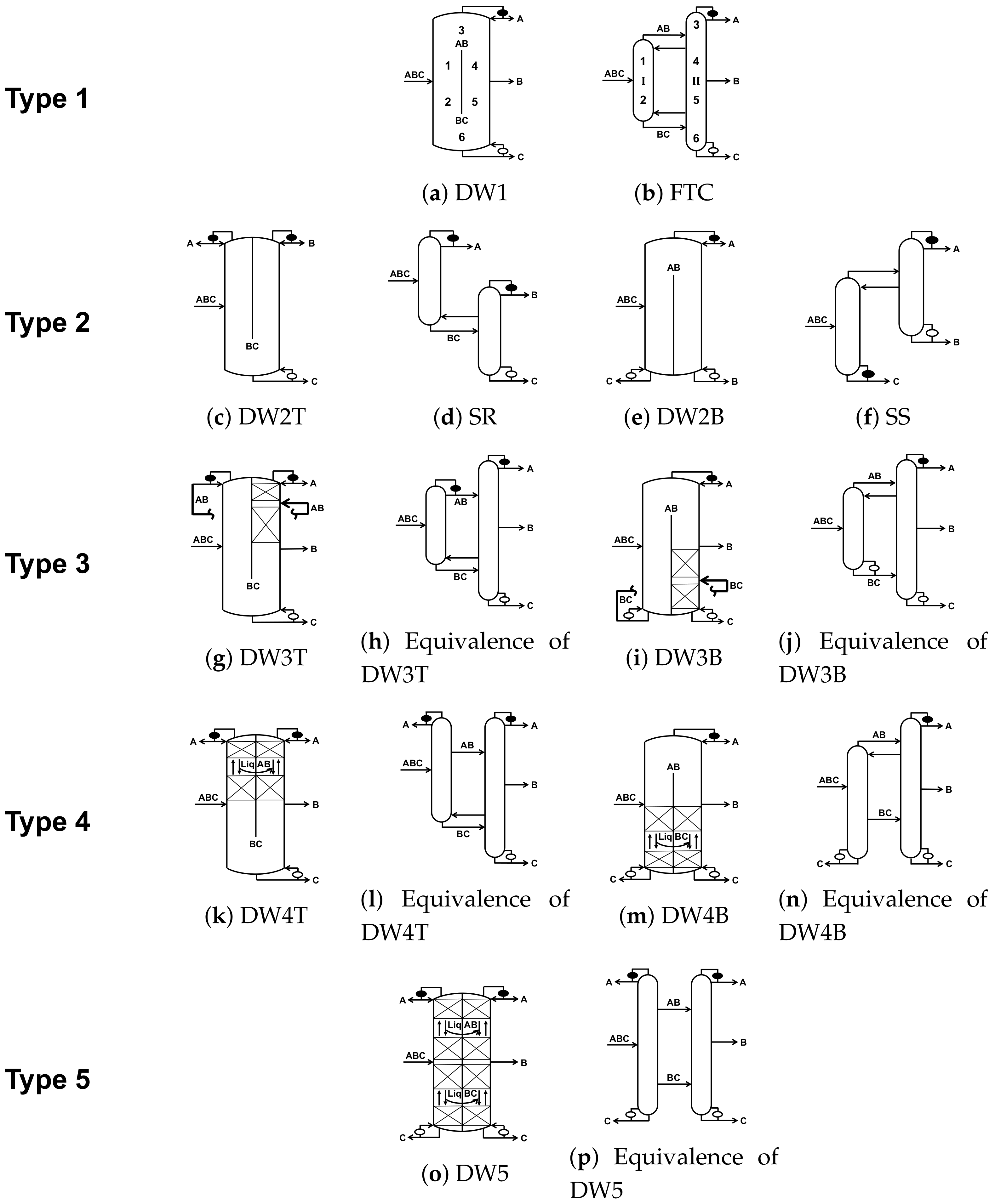
8] (
Figure 1a) is thermodynamically equivalent to the 3-component fully thermally coupled (FTC) configuration (
Figure 1b) which is also known as Petlyuk configuration. Therefore, both versions have identical optimal heat duties. In these figures and all other figures in this article, ABC represents a mixture stream in which A is the most volatile component and C is the least volatile one. Filled circles represent condensers; unfilled circles represent reboilers. For a ternary distillation, the FTC configuration is known to have the lowest heat duty among all basic column configurations and their thermally coupled derivatives [
9,
10,
11,
12]. Therefore, its equivalent DWC in
Figure 1a also has the same lowest heat duty. The energy saving of Wright’s dividing wall column does not come from putting two columns within the FTC configuration into one single shell, but from the inherent thermodynamic properties of the FTC configuration itself.
Agrawal introduced DWC versions for ternary distillations using either side rectifier or side stripper column configurations [
13]. Kaibel used the DWC depicted in
Figure 1a to represent Brugma’s quaternary column configurations [
14,
15]. Later in a series of publications, Madenoor Ramapriya, Tawarmalani and Agrawal (MTA) introduced a systematic method to draw DWC versions for any given thermally coupled column configuration [
7,
16,
17]. Here a thermal coupling refers to a two-way vapor liquid mass transfer between the two columns. It is done to remove a reboiler or a condenser and generally results in lower heat duty [
18]. In
Figure 1b, the condenser at the top of column I is replaced with a thermal coupling, whereby, the vapor stream from the top of this column composed of mainly A and B is sent to the adjoining column II. A liquid stream is withdrawn from the same location as the vapor feed to column II and is fed at the top of the column I as reflux. This results in a thermal coupling between the location I and II at location AB. Similarly, another thermal coupling exists between the bottom of column I and an intermediate location in the bottom half of the column II replacing the bottom reboiler of column I. As shown in
Figure 1a, use of a dividing wall exploits the thermal coupling and merges the two columns in a single shell with all distillation sections 1 through 6 located appropriately.
It is worth noting that introduction of a dividing wall in a column shell does not guarantee that the resulting configuration represents a corresponding thermally coupled column configuration. Such examples can be found in a few US patents [
19,
20]. However, as discussed by Medenoor Ramapriya et al. [
17], those configurations do not represent configurations such as a side rectifier or side stripper and therefore, are unlikely to provide the full benefits of the side rectifier or side stripper configurations. The MTA method ensures that a DWC analog of any given thermally coupled configuration can be correctly drawn.
Historically the practitioners have used the term DWC to refer the DWCs by Wright [
8], Kaibel [
14] and Agrawal [
13]. However, the MTA method has enabled an exhaustive enumeration of DWCs corresponding to any given thermally coupled distillation configuration. For example, for a ternary separation, eight DWC configurations which differ in energy consumption and capital cost have been illustrated [
7]. The number of feasible DWC configurations increase rapidly along with the number of basic configurations as the number of components to be separated increase in a feed mixture [
21]. Therefore, given the huge number of DWCs, the common use of “DWC” to describe a given configuration is no longer adequate in specifying the dividing wall configuration. There is a need to search and classify available dividing wall options.
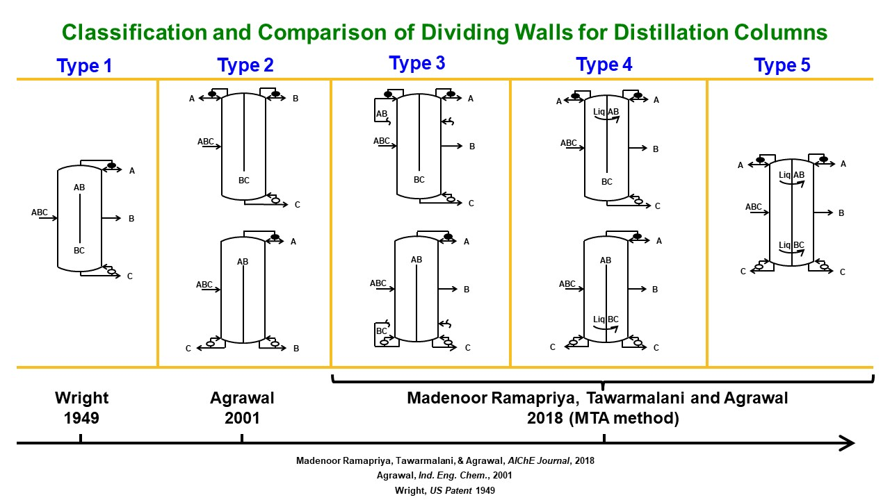
In this work, we classify all possible dividing walls into 5 types based on their unique structural characteristics reflecting their total vapor duty, construction complexity and controllability. For any given thermally coupled column configuration, this classification is expected to simplify choices of dividing wall columns and provide a common language regarding DWCs. We also demonstrate that for a ternary separation, the choice of a dividing wall depends on the feed conditions and finally, we use several 5-component distillation examples to illustrate how to extend our classification beyond ternary separations.
3. Comparison of Minimum Total Vapor Duty
In the classification section, all the dividing walls are classified into 5 types, in which DW1, DW4, and DW5 always have the same minimum total vapor duty. The optimal operating condition of DW1 could be hard to achieve under all operating conditions due to the difficulty in controlling the bottom vapor split. DW4 and DW5, however, get rid of this control difficulty while maintaining the same total vapor duty as DW1. But the trade-off is the addition of an extra liquid transfer stream from one side to the other side of the wall. The other two practically operable alternatives, DW2 and DW3, sacrifice some total vapor duty benefit, but keep the structural simplicity.
The total vapor duty of a certain separation is highly dependent on the feed composition and the relative volatility of each component in the feed. To comprehensively evaluate the performance of these 5 types of dividing wall columns, it is essential to analyze the total vapor duty for different feed composition with different relative volatility sets. For an ABC mixture feed, in which A is the most volatile component and C is the least volatile component, four representative relative volatility sets are chosen:
for easy-easy separation,
for difficult-difficult separation,
for easy-difficult separation and
for difficult-easy separation [
23]. For each relative volatility set and saturated liquid feeds, minimum total vapor duties of all 5 types of dividing wall columns over the entire composition range are calculated to distill pure saturated liquid product streams A, B, and C using the Global Minimization Algorithm (GMA) developed by Nallasivam et al. [
28]. For configurations with more than one reboiler, minimum total vapor duty refers to the minimum of the sum of vapor duty in each of the reboiler. From the minimum total vapor duty perspective, the five types of dividing walls can be divided into three categories. In the first category, DW1, DW4 and DW5, each representing the same FTC configuration, have identical minimum total vapor duties which is the lowest among all the minimum total vapor duties from the DWCs. The other two types of dividing walls DW2 and DW3, generally have different minimum total vapor duties and constitute remaining categories. Depending on the feed conditions and product specifications, the minimum total vapor duty from either DW2 or DW3 may or may not be the lowest total vapor duty. For a given application, it is critical to know the relative differences between the minimum total vapor duties of DW2, DW3 and the lowest heat duty. If the total vapor duty requirements of DW2 and DW3 are similar to DW1, DW4, or DW5, then it is better to choose DW2 or DW3 due to the structural simplicity and operational feasibility. Otherwise, DW4 or DW5 could be a better choice due to heat duty and operation considerations.
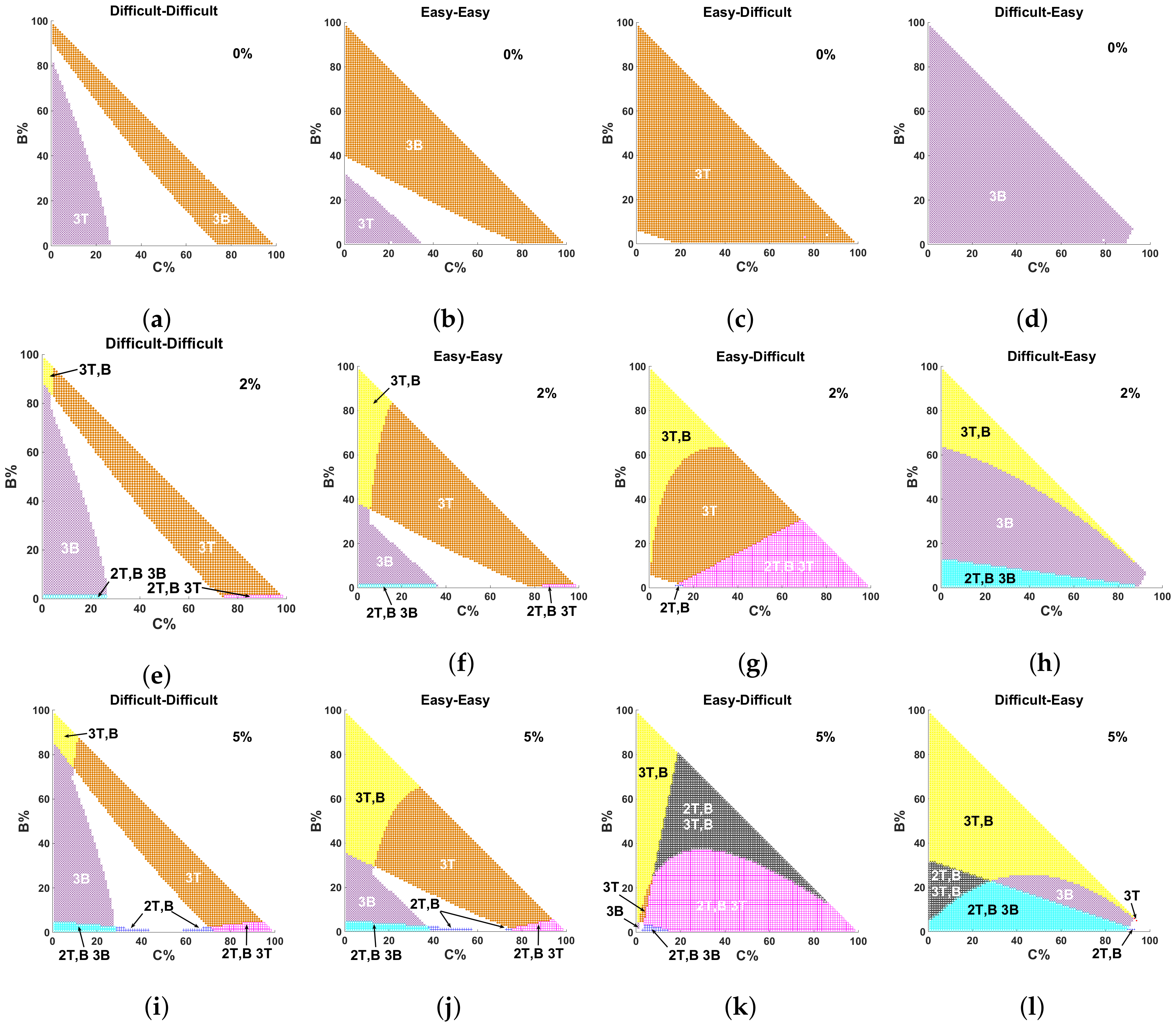
Figure 2 identifies the composition range in which DWC in DW2 or DW3 also have the lowest total vapor duty (
Figure 2a–d, less than 2% (
Figure 2e–h), and less than 5% (
Figure 2i–l) above the lowest heat duty of DW1, DW4, or DW5. In all the figures, the x-axis is the mole fraction of C component in the feed and the y-axis is the mole fraction of B. The mole fraction of A is then calculated by difference. In
Figure 2a–d, DW3B has the lowest heat duty in the purple regions, which is the same as that of DW1, DW4, and DW5. For the feed with composition and relative volatility set lying in these region, DW3B is likely the most attractive dividing wall option due to its structural and operational simplicity with no heat duty penalty. Likewise, DW3T is likely to be the most attractive in the orange regions. It is clear that in
Figure 2a–d, DW3 is the most attractive configuration in a significant composition range. For a difficult-difficult separation (
Figure 2a), the regions for DW3 is 60% of the total area in which purple region is 35% and the orange region is 25%. For an easy-easy separation (
Figure 2b), this number becomes 81% and when it comes to easy-difficult separation (
Figure 2c) or difficult-easy separation (
Figure 2d), DW3 almost always has the lowest total vapor duty for almost every feed composition (99%).
However, DW2 never shows up anywhere in
Figure 2a–d, which indicates DW2 never achieves the lowest total vapor duty, but for structure and operation consideration, DW2 could be an excellent choice, which necessitates further investigation into the situation when some total vapor duty penalty may be acceptable.
Figure 2e–l show the region where the minimum total vapor duties of DW2 and DW3 are within 2% and 5% of the lowest total vapor duties respectively. When 2% total vapor duty penalty is acceptable, DW2 begins to show up in certain composition ranges. The region for DW2 is minor for difficult-difficult and easy-easy separation (
Figure 2e,f), which only account for 1% of the total area. However, for easy-difficult or difficult-easy separation (
Figure 2g,h), this region is comparatively larger, which is 28% and 12% respectively. If the acceptable total vapor duty penalty continues increasing to 5%, the region for DW2 increases to 4%, 4%, 80% and 31% for difficult-difficult, easy-easy, easy-difficult and difficult-easy separation respectively (
Figure 2i–l). Then at least for easy-difficult and difficult-easy separation, DW2 still stands an excellent chance to be the overall most attractive configuration. Moreover, this total vapor duty comparison, along with the structural analysis in the classification section, provides a guideline to choose the proper DWCs. For a given feed composition and relative volatility information, the relative total vapor duty benefit for all 5 types DWC can be easily evaluated from
Figure 2. The optimal DWC configuration is then chosen through a comprehensive consideration of the total vapor duty, structural complexity and operational difficulty.
It is worth noting that we have evaluated all five types of dividing walls in the context of total vapor duty. This analysis is useful when one is concerned about the heat duty for distillation. However, when work rather than heat is used as in a cryogenic distillation or a heat pumped distillation, results could be quite different [
29]. In such cases, for optimal dividing wall choice, it is essential to perform appropriate optimization using exergy as described by Agrawal and coresearchers [
29,
30].
4. Extending Dividing Walls to beyond Ternary Separations
For feed mixtures containing four or more components that need to be distilled into four or more product streams, one needs more than two distillation columns providing large number of distillation column configuration options with thermal couplings [
21]. However, all the thermal coupling column configurations, especially those that do not represent satellite column configurations [
22], can still be represented with the five types of dividing walls that have already been described. We will illustrate this with a few examples.
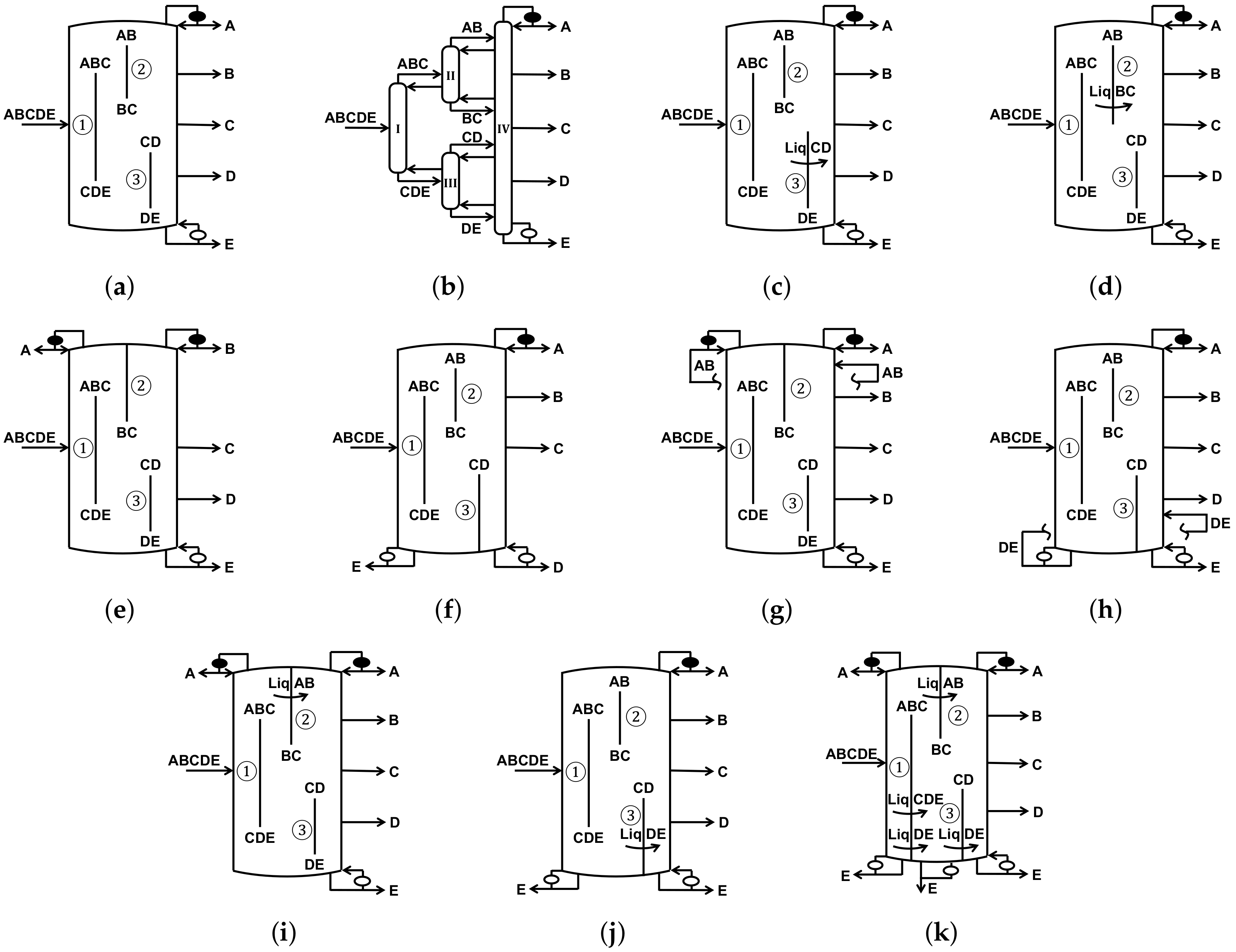
Figure 3a is a configuration that distills a feed mixture into 5 product streams: A, B, C, D and E [
17]. The feed mixture is denoted as ABCDE in which the relative volatility decreases monotonically from A to E. This DWC contains three dividing walls inside one column shell, which are denoted as ①, ② and ③. On the left side of dividing wall ①, the feed stream ABCDE is separated into streams ABC and CDE which go to the right side of this dividing wall through the top and the bottom section respectively. Similar procedures take place on the left side of dividing walls ② and ③ wherein ABC is separated into AB and BC and CDE is separated into CD and DE respectively. One the right side of dividing walls ② and ③, streams AB, BC, CD and DE are separated into A, B, C, D and E. The thermodynamically equivalent column configuration of this DWC is shown in
Figure 3b. In this column configuration, Column I separates the feed mixture ABCDE into ABC and CDE, which is corresponding to the left side of dividing wall ① in
Figure 3a. Columns II and III separate ABC into AB and BC, CDE into CD and DE which are corresponding to the left side of dividing walls ② and ③ respectively. Column IV, from which all five products are collected, is corresponding to the right side of dividing walls ② and ③. Conversely, one can easily draw the DWC in
Figure 3a from the given column configuration in
Figure 3b.
All three dividing walls in this DWC belongs to DW1 as they start at an intermediate location and end at another intermediate location. In a ternary DWC, such a dividing wall never associates with any liquid transfer stream, because once a liquid transfer stream is introduced, one end of the dividing wall must be extended to the top or to the bottom, which results in other types of dividing walls. In a more than three component separation, there are cases when a liquid transfer stream is introduced, but the end of the dividing wall does not extend all the way to the top or the bottom [
17]. It extends towards the top or the bottom but still terminates at some intermediate location, as shown in
Figure 3c,d. The configuration in
Figure 3c can be obtained by extending the dividing wall ③ in
Figure 3a towards but not all the way to the top, and a liquid stream is introduced to transfer liquid CD from one side of the dividing wall to the other. Similarly, the configuration in
Figure 3d can be obtained by extending the dividing wall ② in
Figure 3a. Dividing wall ③ in
Figure 3c and dividing wall ② in
Figure 3d represent cases of Type 1 dividing walls with liquid transfers from one side to the other side of the wall. These DWCs are described in previous work by Madenoor Ramapriya et al. [
7]. These two dividing walls are still classified as DW1. There is no additional condenser or reboiler used in all these configurations which leads to poor controllability of these DWCs since the vapor splits at the bottom of the dividing walls are not regulated.
Some controllable DWCs for a five component distillation are shown in
Figure 3e–j, which contain one or more dividing walls that belong to either DW2, DW3, or DW4 [
17]. Note that while DWC configuration in
Figure 3i–k are thermodynamically equivalent to the one in
Figure 3a, the four other configuration in
Figure 3e–h are not. In
Figure 3e,f, two DWCs containing DW2 (dividing wall ② in
Figure 3e and dividing wall ③ in
Figure 3f) have better controllability than the Figures only containing DW1 (
Figure 3a,c,d) due to the additional condenser (in
Figure 3e) or reboiler (in
Figure 3f). DWCs in
Figure 3e or
Figure 3f can be obtained by replacing dividing wall ② or ③ in
Figure 3a by DW2T or DW2B respectively. On the left side of dividing wall ② in
Figure 3e, ABC is separated into A and BC and A is collected from the condenser on the left top of the DWC. BC travels from the bottom of this dividing wall to the right and is further separated into B and C. Likewise, In
Figure 3f, dividing wall ③ is converted to type 2, CDE is separated into CD and E whereby E is collected from the reboiler on the left bottom of the DWC. CD travels to the right side at the top of this dividing wall and is further separated into C and D. Furthermore, DWCs in
Figure 3g–j can be obtained by converting dividing wall ② or ③ to DW3 or DW4. Similar to the ternary case, the operational advantages of these DWCs are retained since the vapor splits are easily controlled by the additional condenser or reboiler associated with the dividing walls. For configurations in
Figure 3e–h, their minimum total heat duty can also be calculated by transferring them back into their column configuration equivalence using MTA [
7] method and then calculating the minimum heat duty of those configurations via GMA [
28].
One easy-to-operate DWC for this separation is shown in
Figure 3k. Madenoor Ramapriya et al. have shown that for any thermally coupled column configuration, there is always an easy-to-operate DWC version [
17]. A further conclusion one can draw through the analysis in this paper is that, an easy-to-operate DWC does not contain DW1 and a DWC that contains DW1 is difficult to operate. In the DWC shown in
Figure 3k, all three dividing walls belong to DW4. Dividing wall ① belongs to DW4B and two liquid transfer stream, liquid CDE and liquid DE are introduced. dividing wall ② and dividing wall ③ belong to DW4T and DW4B respectively and one liquid transfer stream is associated with each one of these two dividing walls. This DWC has two condensers and three reboilers which could be independently adjusted to tune the vapor split at the bottom of dividing wall ②.
5. Conclusions
Dividing walls are classified into 5 types based on three parameters as shown in
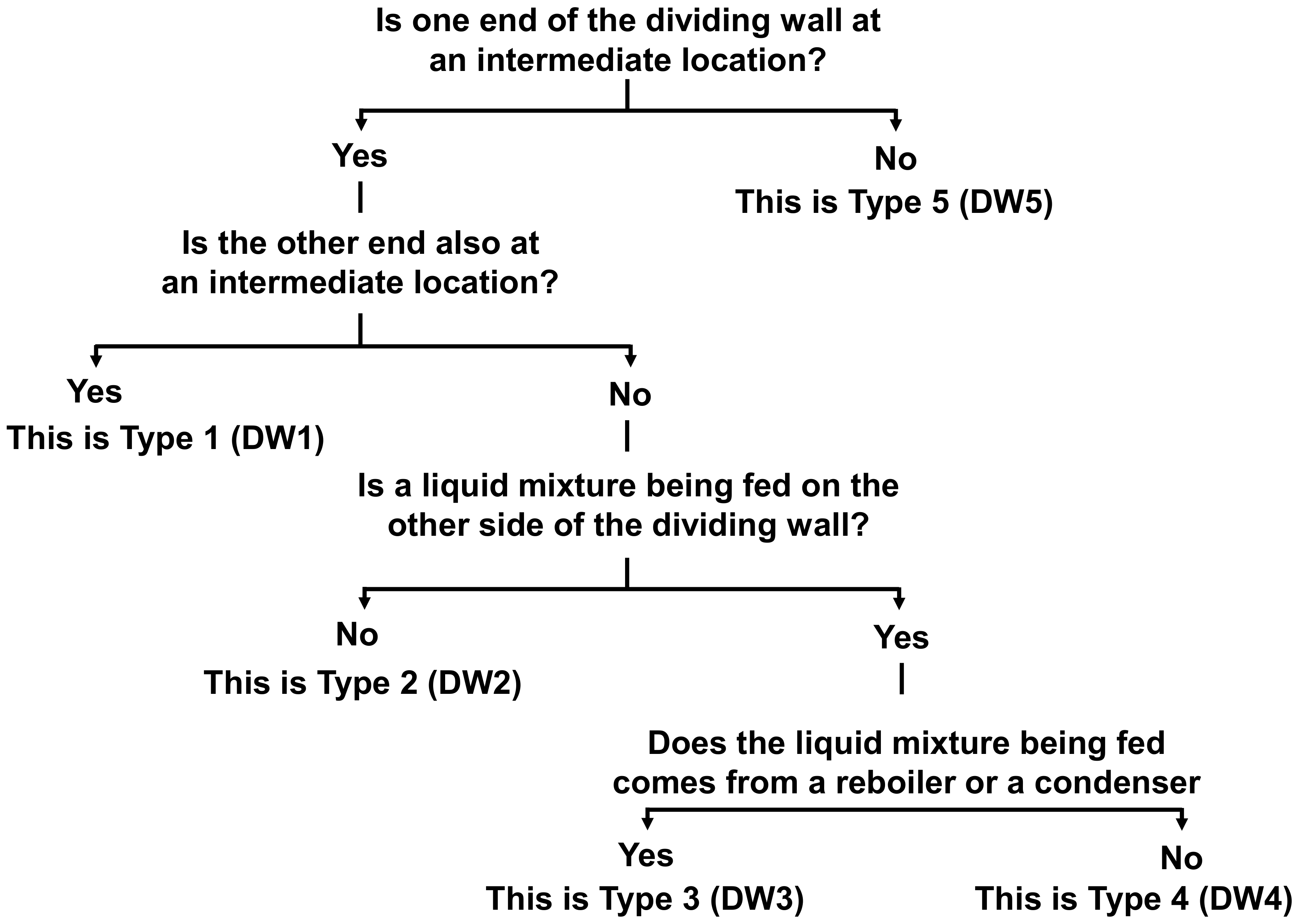
Figure 4: (1) the location of the two ends of the dividing wall (2) the number of condensers and reboilers associated with the dividing wall, and (3) the number and type of transfer streams across the dividing wall. The parameter that differentiates Type 1 dividing wall, DW1, from the rest of the Type 2 through 5 dividing walls is the fact that within a column shell, this dividing wall starts at an intermediate location and ends at another intermediate locaition. The bottom end of the dividing wall is at least a few separation stages below the feed location and the top end is at least a few separation stages above the feed location. While for a three-component feed separation, no liquid stream is transferred from an intermediate location on one side of the wall to an intermediate location on the other side of the wall, this may or may not hold for distillation of feeds containing higher number of components into more than three product streams. All the types 2, 3 and 4 (DW2, DW3 and DW4) are different from the type 5 (DW5) in that these dividing walls start at an intermediate location of the column shell and terminate either at the top or the bottom of the column shell, whereas DW5 traverses from the bottom to the top of the column shell. When the dividing wall starts at an intermediate location that is some separation stages above the feed location, then it extends to the bottom of the column shell providing us with DW2B, DW3B or DW4B. Similarly, when the intermediate location is some separation stages below the feed location, then the other end of the dividing wall extends to the top of the column shell leading to DW2T, DW3T or DW4T. While in type 2 dividing wall, DW2, no liquid mixture is fed at an intermediate location on the other side of the wall, the other two type 3 and 4 (DW3 and DW4) do have such a feed. DW3 has a mixture stream transferred from either a condenser (for DW3T) or a reboiler (for DW3B) to an intermediate location on the dividing wall within the column while in DW4, one such stream is transferred from an intermediate location on one side to an intermediate location on the other side of the dividing wall.
For a ternary mixture, the minimum total vapor duty analysis shows that while DW1, DW4, and DW5 always have the lowest total vapor duty, DW3 also often leads to the same lowest total vapor duty. DW2 also has a good chance to be attractive if a small total vapor duty penalty is allowed. The optimal DWC configuration is chosen through a comprehensive analysis of total vapor duty, energy demand, structural complexity and operation difficulty. We demonstrate that the classification method is easily extendable to more than three component separations.


