Article

Two-Layer Optimization Model for the Siting and Sizing of Energy Storage Systems in Distribution Networks

1
Shennongjia Power Supply Company, Wuhan 442400, China
2
Shiyan Power Supply Company, Wuhan 442000, China
3
School of Electrical Engineering and Automation, Fuzhou University, Fuzhou 350116, China
*
Author to whom correspondence should be addressed.
Processes 2020, 8(5), 559; https://doi.org/10.3390/pr8050559
Submission received: 21 March 2020 / Revised: 28 April 2020 / Accepted: 2 May 2020 / Published: 9 May 2020
(This article belongs to the Special Issue Energy Storage System: Integration, Power Quality, and Operation)

Abstract

:
One of the most important issues that must be taken into consideration during the planning of energy storage systems (ESSs) is improving distribution network economy, reliability, and stability. This paper presents a two-layer optimization model to determine the optimal siting and sizing of ESSs in the distribution network and their best compromise between the real power loss, voltage stability margin, and the application cost of ESSs. Thereinto, an improved bat algorithm based on non-dominated sorting (NSIBA), as an outer layer optimization model, is employed to obtain the Pareto optimal solution set to offer a group of feasible plans for an internal optimization model. According to these feasible plans, the method of fuzzy entropy weight of vague set, as an internal optimization model, is applied to obtain the synthetic priority of Pareto solutions for planning the optimal siting and sizing of ESSs. By this means, the adopted fuzzy entropy weight method is used to obtain the objective function’s weights and vague set method to choose the solution of planning ESSs’ optimal siting and sizing. The proposed method is tested on a real 26-bus distribution system, and the results prove that the proposed method exhibits higher capability and efficiency in finding optimum solutions.

1. Introduction

In recent years, distribution networks using renewable energy such as wind power and photovoltaic power have become one of the research hotspots at home and abroad. After the increasing distributed generations (DGs) are connected to the distribution network, the randomness and intermittency of renewable energy access will have a great impact on the safe and stable operation of distribution networks. Therefore, incorporating ESSs within the distribution network has a positive impact on improving system reliability, such as improved overall energy efficiency, maximized voltage stability, and reduced real power losses [1,2]. Moreover, ESSs are of promising technology with peak shaving, and they facilitate the integration of high penetration levels of renewable energy sources. Despite the above advantages, if the site and size of ESSs are improperly selected, it may cause insufficient voltage stability and economic benefits will decrease [3,4,5]. Therefore, one of the main problems associate with the use of ESSs in distribution networks is to find their best site and size in order to maximize their impact on the grid.
Considering the multidimensional, constrained, and nonlinear characteristic of optimal siting and sizing, the solution techniques for EESs are attained via optimization methods. Much research has proposed different methods such as analytic procedures as well as traditional optimized methods or artificial intelligent methods to solve the problem. Rueda-Medina et al. [6] have introduced a mixed-integer linear programming approach to solve DG siting and siting problems, along with minimizing the annualized investment and operation costs. The works, presented in [7,8], have established an optimal operating model for an integrated ESSs using mixed-integer linear programming. However, increasing with the objective dimension, the shortcomings of poor versatility, low efficiency, and increasingly complex problems prevented the above methods from being widely used.
With the recent advancements in the field of artificial intelligent technique, many intelligent optimization algorithms have been implemented to solve the siting and sizing problem of ESSs in distribution networks. Chen C et al. [9] introduce the genetic algorithm (GA), which is used for the optimal allocation of ESSs to minimize the operation costs of the targeted microgrid based on net present value. A GA is used to optimize the integration of ESSs in [10]. The goals of the optimization are to maximize the profits and minimize network losses. The authors of [11] presented a hybrid method integrating sequential quadratic programming with GA to deal with the problem of optimal allocation of ESSs in unbalanced three-phase low voltage microgrids. The goals of the planning problem are the minimization of the total cost and power quality issue. Arabali et al. [12] presented a technical assessment framework based on particle swarm optimization (PSO), which can effectively minimize the sum of operation and congestion costs over a scheduling period. Mukherjee V [13] have proposed a combined method that is based on symbiotic organisms search (SOS) and chaotic local search (CLS) to find out the optimal location and sizes of real power DGs in a radial distribution system, based on the power loss minimization and voltage profile improvement objective. A grey wolf optimizer is used in [14] to determine the optimal size and location of ESSs in a distribution network to minimize the total annual cost of a system comprising the cost of energy not supplied.
A limitation of the above-listed papers is represented by the fact that they integrated multiple targets into a single target by introducing weights, which led to arbitrariness and subjectivity. In this respect, multi-objective heuristic algorithms are the main means to solve multi-objective optimization problems today because they can eliminate the error of weight. Wang Yongli et al. [15] use a non-dominated sorting genetic algorithm-II (NSGA II) to get the Pareto set and TOPSIS to select the best solution. The goals of the optimal design of the integrated energy system problem are the minimization of the economic, technical, and environmental objectives. Sheng Wanxing et al. [16] and Zhang Shuang et al. [17] apply an improved nondominated sorting genetic algorithm-II to optimal planning of multiple DGs. They formulated their constrained nonlinear optimization problem by line loss, voltage deviation, and voltage stability margin, then obtain the best compromise solution from the Pareto-optimal set based on fuzzy set theory. In [18], a multiobjective particle swarm optimization (MOPSO) has been used to minimize the economic and emission costs of the overall system. In [19], an improved binary bat algorithm (IBBA) has been proposed, which is based on BBA and differential evolution. In this capacity configuration optimization for stand-alone microgrid, the economic, reliability, and environmental criteria should be maximized as the objectives. However, as basic algorithms, the above algorithms have limited local optimality, and their optimal solutions were not stable.
In this paper, three main factors associated with the procedure of ESSs siting and sizing are studied through multi-objective optimization. An improved bat algorithm based on non-dominated sorting (NSIBA) is proposed to optimal allocation and sizing of the ESSs in distribution networks. Due to the iterative local search (ILS) strategy, stochastic inertia weight (SIW) strategy, and balance strategy, NSIBA has significant advantages on optimization accuracy, solution speed, and convergence stability. After obtaining the Pareto optimal set, in order to solve the multi-objective decision problem, the fuzzy entropy weight of vague set as a traditional method was used to obtain the best trade-off solutions from the Pareto optimal solution [20]. This method, however, did not reflect the accuracy of the results because the score function could not fully reflect the relationship between the support, opposition, and neutral target sets. For modifying the above method’s shortcomings, a new score function was proposed to strengthen the influence of unknown information on decision-making. Based on the above, NSIBA and the method of fuzzy entropy weight of vague sets are integrated into a two-layer optimization model that considers several constraints in the process of ascertaining ESSs’ most cost-effective scheme and gives the planner the capability of making the final decision. The effectiveness of the proposed algorithm is validated using the real 26-bus system. To test the effectiveness and reliability of the proposed method, the results are compared with NSGA II and NSPSO; moreover, it demonstrates and verifies that the proposed algorithm can improve a distribution network’s economy and power quality. The rest of this paper is structured as follows. The mathematic formulation is presented in Section 2. The outer layer optimization model of the NSIBA optimization algorithm is constructed in Section 3. Section 4 presents the fuzzy entropy weight of vague set as the internal optimization model. The simulation results are discussed in Section 5, and the conclusion is given in Section 6.

2. Mathematical Problem Formulation

The main objective of current work is to find out the optimal siting and sizing of ESSs in distribution networks, together with minimum network power loss, voltage stability margin, and the application cost of ESSs. Each of the above factors can be considered as an objective function (OF) that is subject to equality and inequality constraints as well as to boundary restrictions imposed by the planner. In mathematical terms, a multi-objective optimization problem can be formulated as follows.
{ min O F ( x ) = ( min O F 1 ( x ) , , min O F m ( x ) ) s . t .             { h ( x ) = 0 g ( x ) 0
Here x = (x1, x2, …, xn) represents the solution to the n-dimensional problem; OF is the target space to the m-dimensional problem; h(x) and g(x) are the equality and inequality constraints, respectively. It is impossible to find a solution to minimize all objectives at the same time when the OFs are in conflict; therefore, the dominance relationship and Pareto optimal solution set are introduced as follows.
Dominance relationship: A solution x(1) is said to dominate another solution x(2) noted as x ( 1 ) x ( 2 ) when (2), (3) are satisfied.
O F i ( x ( 1 ) ) O F i ( x ( 2 ) ) , i = 1 , 2 , , m
O F j ( x ( 1 ) ) < O F j ( x ( 2 ) ) , j = 1 , 2 , , m
Pareto optimal solution set: Pareto optimal solution is the set of all dominating solutions.
P = { x } = { x ( 1 ) x | ¬ x ( 2 ) x : x ( 2 ) x ( 1 ) }

2.1. Objective Function

Considering the evaluation indexes of network power loss, voltage stability margin, and the application cost of ESSs, the mathematical model of multi-objective optimization of ESSs is established as follows:
F = min ( O F 1 ; O F 2 ; O F 3 )
It is impossible to guarantee that all objective functions can achieve a relative minimum at the same time. Therefore, the Pareto optimal solution set is introduced to search the frontier solution in the target region.
(1) Network power loss. In the process of ESSs’ siting and sizing, minimize the power loss as much as possible is the first and foremost objective. The power losses depend on the impedances of line and transformer. Incorporating ESSs within the distribution network has a positive impact on reducing the network power loss and improving the electric efficiency of the distribution network. Therefore, under ESSs’ optimal configuration, the scheme with low total network power loss should be considered.
The equivalent models of transformer and line are shown in Figure 1. The objective function of network power loss can be expressed as
O F 1 = P loss = P tran + P line
P line = R i j U i U j ( i = 1 N j = 1 N cos ( θ i θ j ) ( P i P j + Q i Q j ) + sin ( θ i θ j ) ( Q i P j P i Q j ) )
Here, Ploss is the total losses of the distribution network. Ptran is the rated active power of the transformer. Pline is the active loss of line. Rij is the resistance of the distribution line connecting the ith and jth buses. Ui is the ith bus voltage. N is the total number of buses in the distribution network. θi is the ith phase angle. Pi and Qi are the active and reactive powers of the ith bus, respectively.
(2) Voltage stability margin. The bus voltage of the network often experiences fluctuations with the increase of load and DGs. ESSs connected to the network properly are conducive to improving the overall voltage profile. The objective function of the voltage stability margin can be stated as follows:
O F 2 = D dev = i = 1 N ( U i U e U p ) 2
Here, Ue is the rated voltage. Up is the rated voltage allowable deviation, namely, Up = 0.05.
(3) Application cost. The ESSs’ application cost includes investment and operation costs. In order to pursue a higher economy, smaller operating and investment costs must be considered. Therefore, the general formula of the objective function can be described as follows:
O F 3 = G 3 = ( r ( 1 + r ) a ( 1 + r ) a 1 C D G I n v s + C D G O p e r ) S E S S s
Here, r is the discount rate; a is ESSs’ lifetime; C D G I n s and C D G O p e r are the investment cost and operating cost of the unit ESSs, respectively; S E S S s is the ESSs’ total investment capacity.

2.2. Equality Constraints

Due to the advantages of fewer iterations, simplicity, and flexibility, the back/forward sweep method is widely adopted in distribution networks. Therefore, under operating frequency conditions, the conserved formula of the active and reactive powers at a certain bus can be expressed as
P i + P i E S S = P L i + U i j = 1 N U j ( G i j cos θ i j + B i j sin θ i j )
Q i = Q L i + U i j = 1 N U j ( G i j sin θ i j B i j cos θ i j )
Here, P i E S S is ESSs’ output active and reactive powers of the ith bus, respectively. PLi and QLi represent the active and reactive powers losses of the load, respectively. Gij and Bij are conductance and susceptance, respectively. θij is the angle of the distribution line connecting the ith and jth buses.

2.3. Inequality Constraints

The node voltage, ESSs installed capacity, branch current, and SOC are bounded between two extreme levels forced by physical limitations.
U i , min U i U i , max
0 S i E S S s S i , max E S S s
0 < I i j < I i j , max
Here, S i E S S is the total capacity of the ith ESSs. Iij is the current of the distribution line connecting the ith and jth buses. In order to protect the service life of the ESSs, the SOC must be limited to prevent the overcharge and overdischarge of ESSs.
P min < | S O C t + Δ t S O C t | E E S S i Δ t < P max
20 % < S O C < 90 %
Here, Pmax and Pmin are the maximum and minimum power of ESSs. In addition, in order to extend the useful life of the ESSs, we set the usage range of the ESSs’ SOC as 20% to 90%.

3. Outer Layer Optimization Model

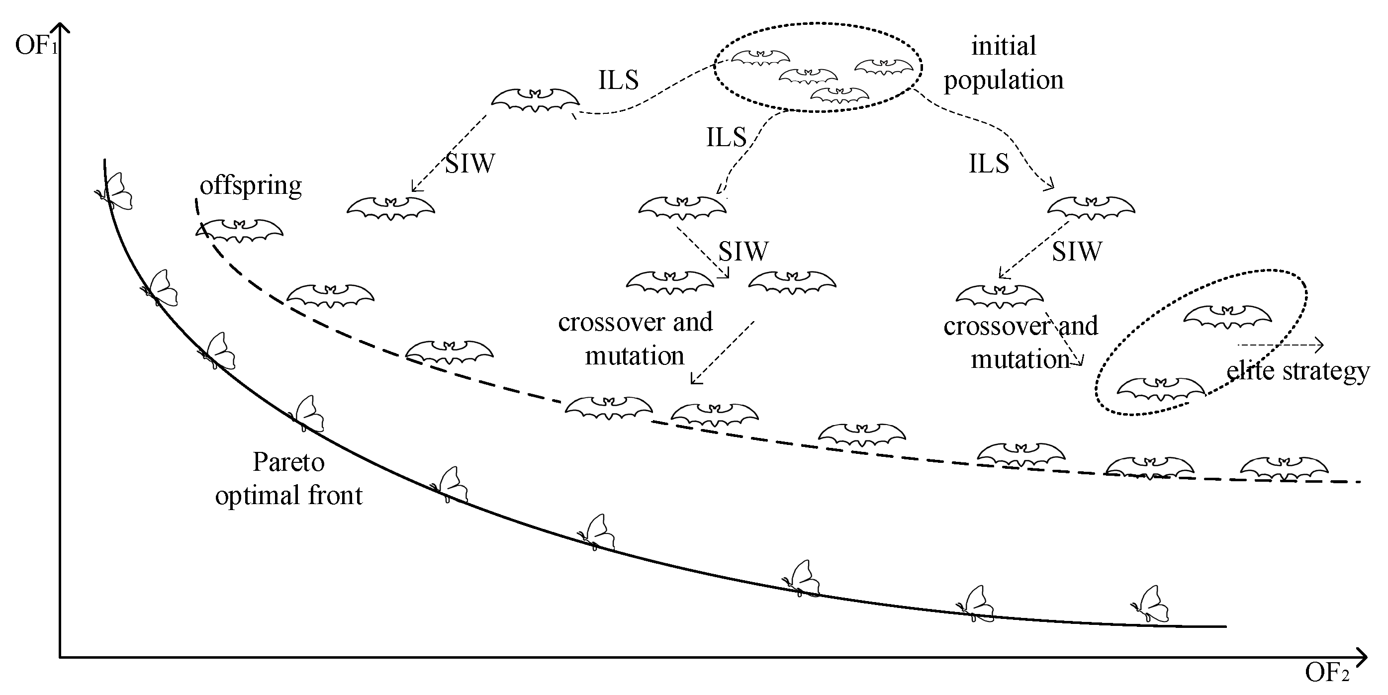
ILSSIWBA is a swarm intelligence optimization algorithm based on local iterative search and random inertia weights proposed by Chao Gan [21]. The basic framework of ILSSIWBA is similar to the previous bat algorithm (BA), which is popular in solving optimization problems. However, differing from the BA, ILSSIWBA introduces the local optimal solution and the global inertia weight, which can make the optimal solution more stable. This paper combines ILS strategy, SIW strategy, and balance strategy with a non-dominated sorting strategy. NSIBA is proposed to obtain the Pareto optimal front, which can solve the multi-objective optimization problem with faster convergence speed. This algorithm is described in Figure 2.

3.1. ILS Strategy

ILS strategy is introduced to make the target jump out of the local optimal solution [22], which is defined as follows.
x = { x * * = x rand ,       if   [ ( O F ( x * * ) O F ( x ) ) | ( O F ( x * * ) O F ( x ) & e ( O F ( x ) O F ( x ) ) > rand ) ] x ,                                             otherwise
{ O F ( x * * ) O F ( x ) i f       ( O F 1 ( x * * ) < O F 1 ( x ) ) + ( O F 2 ( x * * ) < O F 2 ( x ) ) + ( O F 3 ( x * * ) < O F 3 ( x ) ) 2
Here x is the current optimal solution; x is the perturbation solution. Because multi-objective functions cannot be compared directly, the judgment condition is improved: it is equivalent to single-objective comparison when there are at least two OFs values that are less than the comparison value.

3.2. SIW Strategy

Stable solutions are obtained by introducing the SIW strategy, which updates the bat pulse frequency, position, and velocity as follows [23].
f = f min + rand ( 0 , 1 ) × ( f max f min )
X i t = X i t 1 + V i t
V i t = ω V i t 1 + ( X i t X * ) f i
ω = μ min + ( μ max μ min ) × rand + σ × rand
Here, f is the frequency of bat; fmax and fmin are the maximum and minimum value limits of the frequency; X i t and V i t are the position and velocity of bat in the tth iterations, respectively; ω is the random inertia weight; μmax and μmin are the maximum and minimum influencing factors of the inertia weight, respectively; σ is the deviation coefficient; rand is a uniformly distributed random number.
This strategy introduces a weight coefficient for the bat speed update and adjusts the weight by using random variables, which is beneficial to solve the problem of optimal solution instability in traditional BA.

3.3. Balance Strategy

In order to balance the local and global solutions, new emissivity and volume update formulas are adopted, in which the pulse emissivity controls the search of the bat in local and global, and the volume controls the acceptance of the new solution. The volume and pulse emission rate are updated by
{ A i t = ( A 0 A 1 t max ) ( t t max ) + A r t = ( r 0 r 1 t max ) ( t t max ) + r if { rand < A i t O F ( x i t ) < O F ( x )
Here, At is the bat volume in t iterations; r0 and A0 are the initial pulse emissivity and volume, respectively; r and A are the maximum values of initial pulse emissivity and volume, respectively.

3.4. Non-Dominant Sorting and Elite Preservation Strategy

Fast non-dominant is a key feature in stratifying the population according to the level of the Pareto optimal solution set and making the target closer to the Pareto optimal front. The procedures of non-dominant sorting and elite strategy are given as follows [24]:
(1)
For each bat xi, set two parameters np and sp, where np is the number of solutions that dominate the solution p; sp is a set of solutions that the solution p dominates.
(2)
Find the non-dominated solution set with np = 0 and set the non-dominated rank as Rank1.
(3)
For each individual xj in Rank1, check the corresponding sj. For each xk in sj, set the parameter np = np−1; if np = 0, set xk as Rank2. Then repeat the above steps until the non-dominated ranks of all bats are determined.
(4)
Crowding distance is introduced to characterize the distance between two bats, to make the distribution of bats more uniform in space, which can be formulated as follows:
D x = | O F i ( x + 1 ) O F i ( x 1 ) | O F i , max O F i , min
(5)
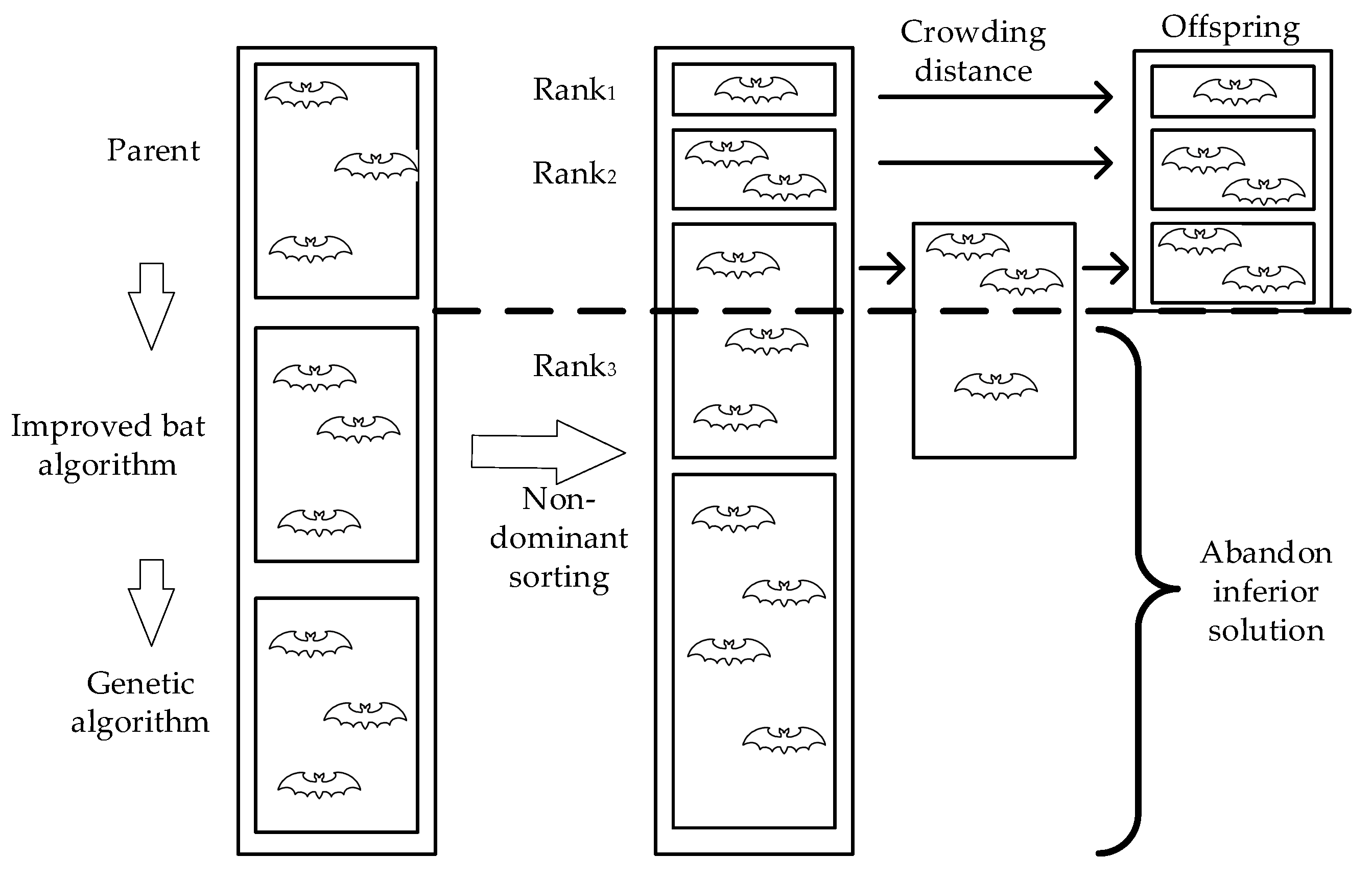
Elite strategy. Elite preservation strategy combines the parents and individuals generated by improved bat algorithm and genetic algorithm to form a set with the size of 3N and selects N individuals with better performance to form the offspring generation. In the selection operation, the solution with the smaller non-dominated Rank and the bigger crowding distance have priority to be chosen than others when the non-dominated Rank is the same. The main idea of elite strategy is given in Figure 3.

4. Internal Layer Optimization Model

After the Pareto optimal front is obtained through the outer optimization model, the optimal solution can be selected by setting different weights. Due to the difference and ambiguity of weight caused by different design schemes, the fuzzy entropy weight of the vague set is used to reduce the errors caused by decision making.

4.1. Analytic Hierarchy Process (AHP)

AHP is a subjective weight method, which determines the weight through the historical experience or subjective preference of the decision made. The calculation process is given below.
(1)
Construct a judge matrix. In order to make the scheme have a unified standard, the numbers 1–9 and their inverses are used as scales to define the judge. The comparative important scale of criteria is given in Table 1.
(2)
Arithmetic mean estimated weight vector.
ω AHP = 1 n j = 1 m f i j k = 1 n f k j               i = 1 , 2 , , N
Here, ωAHP is the weight value corresponding to each OF; the elements in the judgment matrix are normalized and averaged to obtain the weight vector.

4.2. Fuzzy Entropy Weight

The entropy weight method uses information entropy to describe the objectivity of information, and objectively determines the weight of attributes based on the degree of information difference in the decision matrix. The calculation process is given below:
(1)
Normalization is represented as follows:
O F j ( x i ) = max O F j O F j ( x i ) max O F j min O F j
p i j = O F j ( x i ) i = 1 N O F j ( x i )
(2)
The entropy is represented as follows:
e j = K i = 1 n p i j ln p i j             ( K = 1 / ln n , e j 0 )
(3)
The entropy method weight is represented as follows:
ω e = 1 e j j = 1 N ( 1 e j )
(4)
The fuzzy entropy weight is represented as follows:
ω i = ω AHP i × ω e i i m ω AHP i × ω e i

4.3. Fuzzy Entropy Weight of Vague Set

Due to the ambiguity and uncertainty of the information, the linear weighting method often loses some useful information in multi-objective decision making. Therefore, Gau proposed the concept of the vague set based on the fuzzy set [25], which divides the membership function of each element into support and opposition. The vague set of A can be formulated as follows:
A = { [ t A ( u i ) , 1 f A ( u i ) ] | u i U , t A ( u i ) [ 0 , 1 ] , f A ( u i ) [ 0 , 1 ] , π A ( u i ) U ,   t A ( u i ) + f A ( u i ) 1 , t A ( u i ) + f A ( u i ) + π A ( u i ) = 1 }
Here, U is the universe of discourse; ui denotes a generic element of U; tA(ui) is lower bound on the grade of membership on the evidence for ui and fA(ui) is a lower bound on the negation of ui derived from the evidence against ui. πA is the degree of hesitation of the vague set A. The larger the value of πA is, the more unknown information it may contain. The vague set can be interpreted as tA(ui) and fA(ui) are the number of votes in favor and against; πA is the abstention.
As a generalization of fuzzy sets, vague fuzzy sets consider both membership and non-membership information, so they can more fully express fuzzy information in multi-objective decisions. The decision process is as follows:
(1)
Determine the positive and negative ideal solutions P+, P, and then calculate the solution of vague set A = ([tAij, fAij])n×m.
P + = { P 1 + , P 2 + , , P m + } ; P = { P 1 , P 2 , , P m }  
{ t i j + = P i j P j P j + P j t i j + = P j + P i j P j + P j f i j + = P j + P i j P j + P j f i j + = P i j P j P j + P j
t i j = t i j + f i j           f i j = t i j f i j +
Here, P+ and P are the best and worst solution for each attribute to reach candidate solution, respectively; the true and false membership of Pij relative to the positive ideal index P+ and the negative ideal index P are shown in (35). The comprehensive vague membership is shown in (36).
(2)
Determine the comprehensive vague value of each ideal solution in the Pareto optimal front, which can be described as follows:
t A i = i = 1 m ω i t i j , f A i = i = 1 m ω i f i j ,     ( i = 1 , 2 , , n )
(3)
Sort the solutions by a new score function to choose the best solution.
S i = t A i f A i 1 + π A i
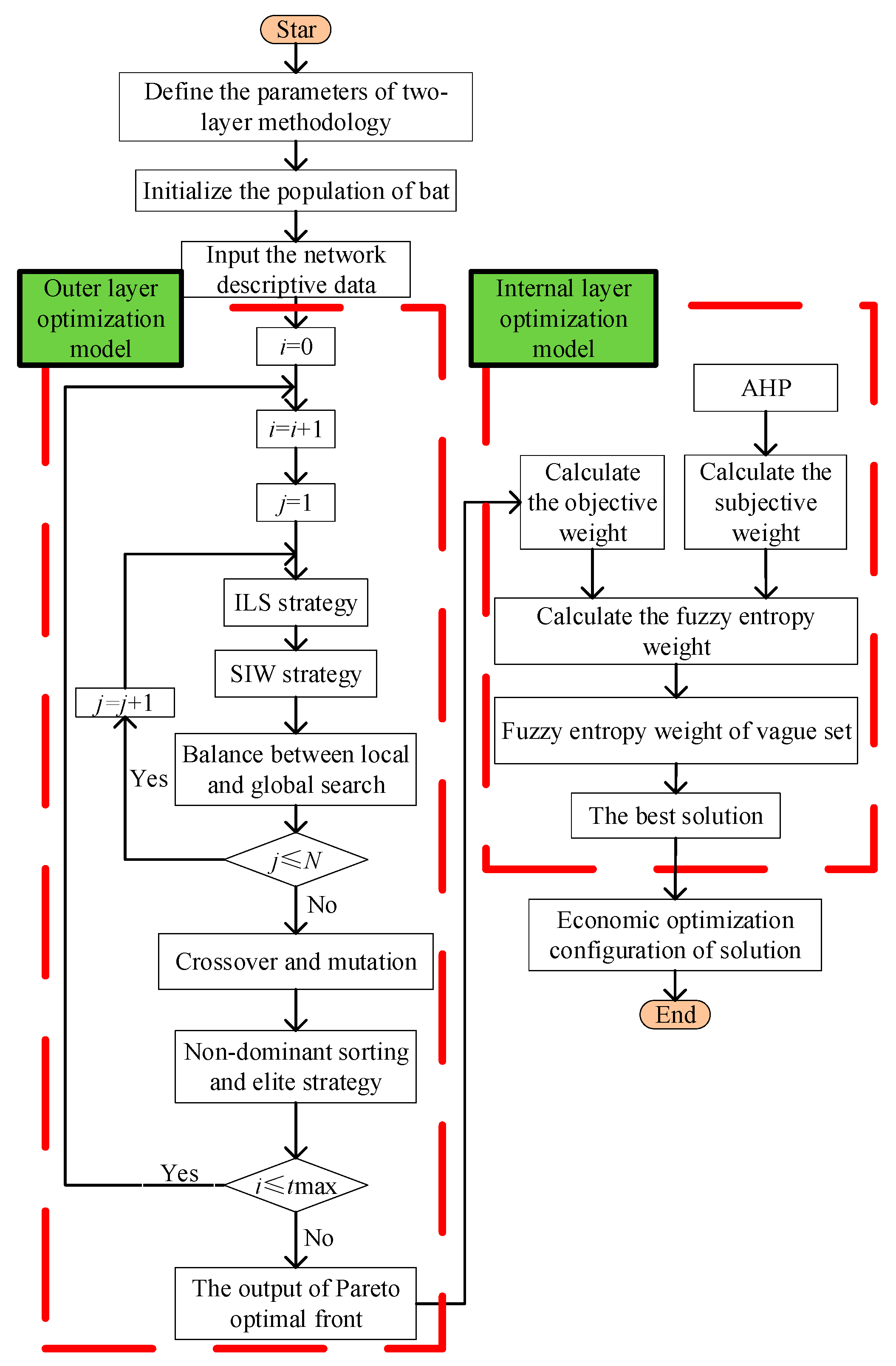
The new score function not only emphasizes the difference between true and false membership degrees but also strengthens the influence of unknown information on decision-making. Obviously, the greater Si is, the more credible of the scheme is. The flowchart based on the two-layer optimization model is shown in Figure 4.
When the optimal configuration analysis of the obtained scheme is carried out, the comprehensive evaluation mainly based on the system’s operating economy has attracted much attention. Therefore, the three OFs constructed in the study are converted into economic indicators, and the economic optimization configuration of ESSs are analyzed by calculating the following costs [26,27,28]:
G 1 = a C ep 1 365 t = 1 24 Δ t P loss , t
G 2 = a C ep ω 1 365 t = 1 24 Δ t D dev , t
Here, G1 is the cost of network power loss; Cep is the cost of unit network power loss; Ploss,t is the network power loss at time t; Δ t is equal to 1 h; G2 is the cost of the voltage stability margin; Ddev,t is the voltage stability margin at time t; ω is the conversion coefficient between the total line loss and voltage stability margin.
ESSs in distribution networks not only have fast corresponding speed but also have the advantages of “spread arbitrage”, which can alleviate the power supply tension during the peak of power consumption. Therefore, in conjunction with peak and valley power prices, it can reduce economic costs.
G 4 = a n l o s s C ebuy 1 365 1 i S i E S S s
Here G4 is the benefits of economical recycling; Cebuy is the peak-valley unit price spread; the loss of the ESSs in its life cycle is expressed as nloss, which is equal to 0.95.

5. Simulation Results and Discussion

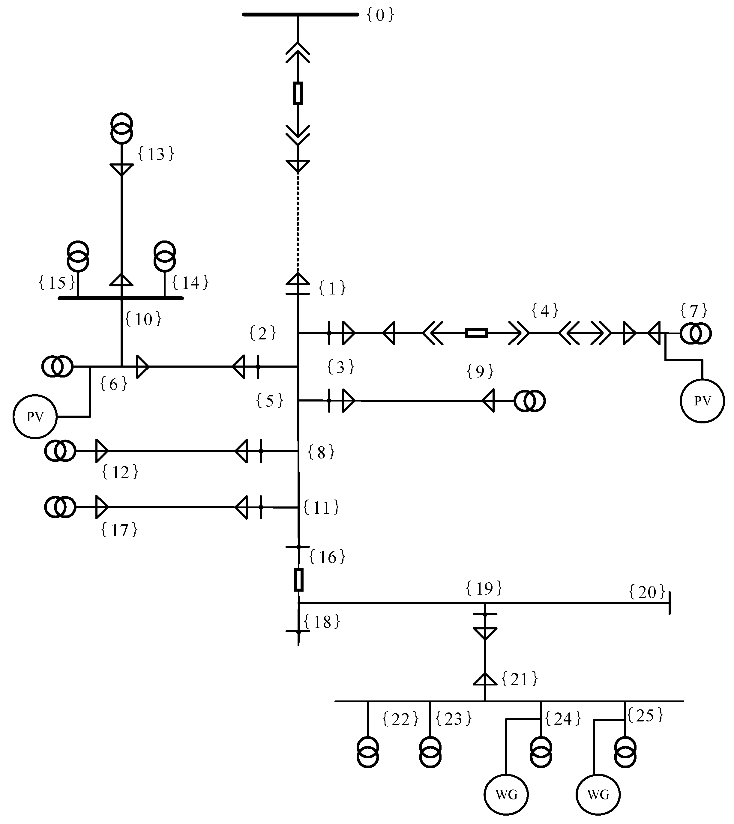
The proposed algorithm is implemented on a 26-node system of a 10-KV substation that is depicted in Figure 5. The system contains 12 transformers, where the transformer nodes are set as candidate nodes for ESSs.

5.1. Algorithm Performance Analysis

NSGA II, NSPSO, and NSIBA are applied in this paper to compare the performance for solving multi-objective optimization problems. Algorithm parameters are set as follows: The maximum iteration is 300; the bat population is 50; the initial and maximum value of the pulse emissivity are 0.1 and 0.7, respectively; the initial and minimum values of the volume are 0.9 and 0.6, respectively; maximum and minimum values of inertia weight are 0.9 and 0.4, respectively; the coefficient of deviation is 0.2; lifetime a = 10 year; discount rate r = 10%; investment cost C D G I n s = 172 USD/kW and operating cost C D G O p e r = 257 USD/kW; the cost of unit network power loss Cep= 0.07 USD/(kW h); the peak-valley unit price spread Cebuy = 0.083 USD/(kW h).
The convergence curves of OFs are depicted in Figure 6. As shown in Figure 6, OF1 and OF2 of NSIBA have a sharp decline in the first 50 iterations. It can be affirmed that NSIBA has quicker convergence speed and better search accuracy than other algorithms.
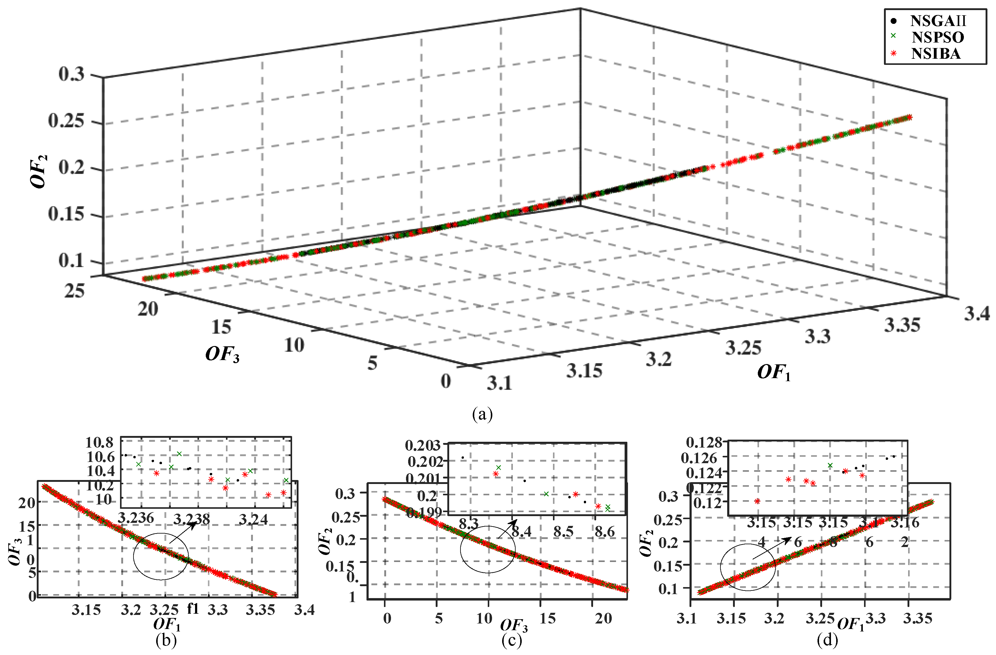
In order to explain the performance of NSIBA further, Figure 7 shows the Pareto optimal front obtained by different approaches. Comparing the OF values, the solutions by NSIBA has a significant advantage than other algorithms, which not only distributes more uniformly in the Pareto optimal front but also has a wider range of solution set distribution. Therefore, the NSIBA algorithm can search for more possible solutions and avoid falling into a local optimum.

5.2. Scheme Economic Analysis

In the actual operation of a distribution network, affordability is gradually increasing as the load increases. Therefore, this section compares the economics of ESSs with capacity expansion equipment such as transformers and analyzes the optimal configuration of the ESSs, which is listed in Table 2.
In order to realize the comparison in the same conditions, it supposes that the capacity of the transformer is increased from 315 to 500 kVA on the bus where the ESSs are installed. The expansion of the transformer is generally increased by 50% of the original equipment capacity. The transformer upgrade cost is about USD 6857.14, which is represented by G3 in Table 2. From the comparison results, we can see that G1 and G2 within ten years has a small difference in the two scenarios. Although the investment cost G3 of ESSs is higher than that of traditional transformer expansion, the cost-saving through “ESSs high storage and low generation” is enough to make up for investment cost and achieve capital recovery. Therefore, in comparison to the expansion of traditional transformers, the configuration of ESSs can bring more economic benefits to the network.

5.3. Scheme Effectiveness Analysis

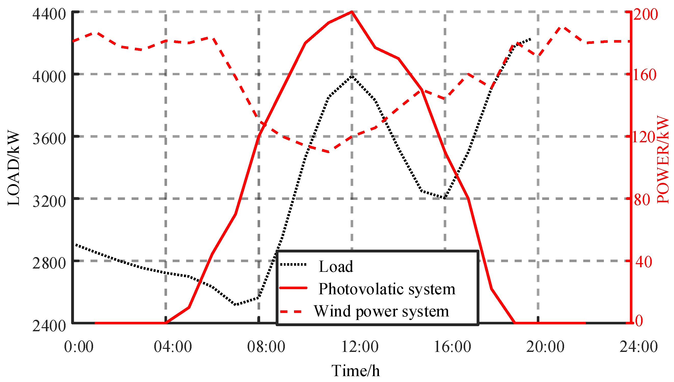
In order to enrich the background of the example, 200 kW photovoltaic systems are connected at bus 6 and 7, and a 200-kW wind power system is connected at bus 24 and 25. The typical daily characteristic curves of load, photovoltaic, and wind power are shown in Figure 8.
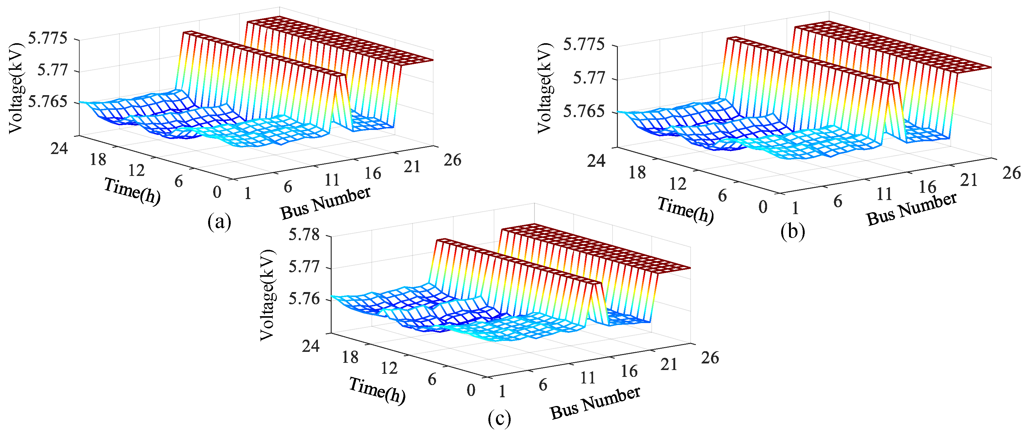
In order to verify the effectiveness of the scheme, three scenarios are established for comparison.
  • Scenario 1: The network without DGs and ESSs.
  • Scenario 2: The network with DGs only.
  • Scenario 3: The network with both DGs and ESSs.
The typical daily system voltage at each bus is shown in Figure 9. Comparing Scenario 1 with Scenario 2, due to the randomness of power output by DGs, the system voltage has a large deviation, and the total line loss of the system has increased greatly. Comparing Scenario 2 with Scenario 3, the adjustability of ESSs can greatly suppress the voltage fluctuation, which is of great significance to the safe and stable operation of the system. Thus, the ESSs performs very well in terms of suppressing bus voltage fluctuation and load fluctuation.
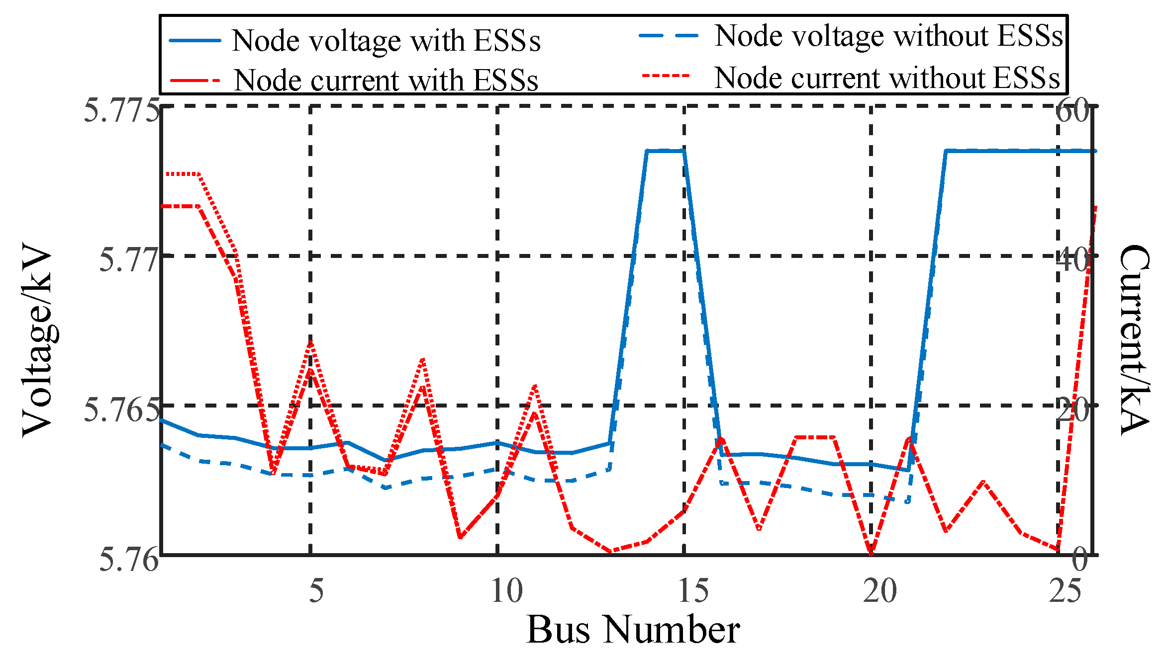
The voltage and current of each bus at 20 h are shown in Figure 10. The voltage amplitude increases toward the value of the rated voltage, and the current amplitude is smaller than the corresponding value in Scenario 1. The voltage and current quality of the network with ESSs have been significantly improved, which not only help improve the accommodation ability of the network, but also verify the practicability of the proposed two-layer optimization model.

6. Conclusions

According to the network power loss, voltage stability margins, and application costs of ESSs, this paper proposes a two-layer optimization model for the optimal siting and sizing of ESSs. Based on a theoretical analysis and simulation verification, the following conclusions can be drawn:
(1)
This paper establishes a two-layer optimization model by integrating NSIBA and fuzzy entropy weight of the vague set. The proposed NSIBA can keep the population evolving during the search and jump out of the local optimal solution due to the integration of ILS strategy, SIW strategy, and balance strategy within it. The proposed fuzzy entropy weight of the vague set can strengthen the influence of unknown information on decision-making due to the integration of the new score function. The two-layer optimization model can fairly and reasonably give decision-makers a comprehensive plan.
(2)
The proposed method is tested on a real 26-bus distribution system. The convergence curve and Pareto optimal front show that NSIBA has the quicker convergence speed and better search accuracy than NSGA II and NSPSO. The simulation in different scenarios demonstrates that the proposed scheme not only can achieve arbitrage of USD 2612.22 by “ESSs high storage and low generation”, but also improve the power quality when accessing the DGs. Hence, it may be concluded that the proposed two-layer optimization model is a good choice over the other algorithm for determining the optimal siting and sizing of ESSs in distribution networks. It will be very useful for decision-making in the optimal configuration of ESSs using simulation tools.

Author Contributions

F.Z. and T.S. conceived and designed the study. L.Z. performed the simulation. P.Z. and X.X. provided the simulation case. Y.C. and T.S. wrote the paper. F.Z. and T.S. reviewed and edited the manuscript. All authors have read and agreed to the published version of the manuscript.

Funding

This research was funded by the science and technology project of State Grid Hubei Electric Power Co. LTD through grant number 5215C018002H and the Natural Science Foundation of Fujian Province, China, through grant number 2019J01249.

Conflicts of Interest

The authors declare no conflict of interest.

References

  1. Mohamed, A.; Mohammad, A. Two Stage Methodology for Optimal Siting and Sizing of Distributed Generation in Medium Voltage Network. In Proceedings of the IEEE Green Technol. Conference, Kansas City, MO, USA, 6–8 April 2016. [Google Scholar]
  2. Jia, H.; Mu, Y.; Yu, X. Thought about the Integrated Energy System in China. Power Constr. 2015, 36, 16–25. [Google Scholar]
  3. Shi, J.; Qiao, Y.; Wang, Y.; Wen, J.; Tong, J.; Zhang, J. The Planning of Distribution Network Containing Distributed Generators Based on Mixed Integer Linear Programming. In Proceedings of the International Conference on Electric Utility Deregulation & Restructuring & Power Technologies, Changsha, China, 26–29 November 2015; pp. 449–453. [Google Scholar]
  4. Kaur, S.; Kumbhar, G.; Sharma, J. A MINLP Technique for Optimal Placement of Multiple DG Units in Distribution System. Int. J. Electr. Power Energy Syst. 2014, 63, 609–617. [Google Scholar] [CrossRef]
  5. Mena, A.J.G.; García, J.A.M. An Efficient Approach for the Siting and Sizing Problem of Distributed Generation. Int. J. Electr. Power Energy Syst. 2015, 69, 167–172. [Google Scholar] [CrossRef]
  6. Rueda-Medina, A.C.; Franco, J.F.; Rider, M.J.; Padilha-Feltrin, A.; Romero, R. A mixed-integer linear programming approach for optimal type, size and allocation of distributed generation in radial distribution systems. Electr. Power Syst. Res. 2013, 97, 133–143. [Google Scholar] [CrossRef]
  7. De Quevedo, P.M.; Contreras, J. Optimal Placement of Energy Storage and Wind Power under Uncertainty. Energies 2016, 9, 528. [Google Scholar] [CrossRef] [Green Version]
  8. Ochoa, L.F.; Harrison, G.P. Minimizing energy losses: Optimal accommodation and smart operation of renewable distributed generation. IEEE Trans. Power Syst. 2011, 26, 198–205. [Google Scholar] [CrossRef] [Green Version]
  9. Chen, C.; Duan, S.; Cai, T.; Liu, B.; Hu, G. Optimal Allocation and Economic Analysis of Energy Storage System in Microgrids. Power Electron. IEEE Trans. 2011, 26, 2762–2773. [Google Scholar] [CrossRef]
  10. Zheng, L.; Hu, W.; Lu, Q.; Min, Y.; Yuan, F.; Gao, Z.H. Research on planning and operation model for energy storage system to optimize wind power integration. Proc. Chin. Soc. Electr. Eng. 2014, 34, 2533–2543. [Google Scholar]
  11. Carpinelli, G.; Mottola, F.; Proto, D.; Russo, A.; Varilone, P. A Hybrid Method for Optimal Siting and Sizing of Battery Energy Storage Systems in Unbalanced Low Voltage Microgrids. Appl. Sci. 2018, 8, 455. [Google Scholar] [CrossRef] [Green Version]
  12. Arabali, A.; Ghofrani, M.; Etezadi-Amoli, M. Cost analysis of a power system using probabilistic optimal power flow with energy storage integration and wind generation. Int. J. Electr. Power Energy Syst. 2013, 53, 832–841. [Google Scholar] [CrossRef]
  13. Mukherjee, V.; Saha, S. Optimal placement and sizing of DGs in RDS using chaos embedded SOS algorithm. IET Gener. Transm. Distrib. 2016, 10, 3671–3680. [Google Scholar]
  14. Fathy, A.; Abdelaziz, A.Y. Grey Wolf Optimizer for Optimal Sizing and Siting of Energy Storage System in Electric Distribution Network. Electr. Power Compon. Syst. 2017, 45, 601–614. [Google Scholar] [CrossRef]
  15. Wang, Y.; Wang, X.; Yu, H.; Huang, Y.; Dong, H.; Qi, C.; Baptiste, N. Optimal design of integrated energy system considering economics, autonomy and carbon emissions. J. Clean. Prod. 2019, 225, 563–578. [Google Scholar] [CrossRef]
  16. Sheng, W.; Liu, K.Y.; Liu, Y.; Meng, X.; Li, Y. Optimal Placement and Sizing of Distributed Generation via an Improved Nondominated Sorting Genetic Algorithm II. Power Deliv. IEEE Trans. 2015, 30, 569–578. [Google Scholar] [CrossRef]
  17. Zhang, S.; Liu, Y.M.; Gao, F.; Tian, B. Optimal Placement and Sizing of Distributed Generation in Smart Distribution System. Appl. Mech. Mater. 2014, 513–517, 3322–3327. [Google Scholar] [CrossRef]
  18. Phonrattanasak, P. Optimal placement of DG using multiobjective particle swarm optimization. In Proceedings of the International Conference on Mechanical and Electrical Technology, Singapore, 10–12 September 2010; pp. 342–346. [Google Scholar]
  19. Sheng, S.; Zhang, J. Capacity configuration optimisation for stand-alone micro-grid based on an improved binary bat algorithm. J. Eng. 2017, 2017, 2083–2087. [Google Scholar] [CrossRef]
  20. Zhang, J.Y.; Liu, Y.; Huo, M.L. The Maintenance Decision Optimization for Distribution Networks Based on the Fuzzy Entropy Weight of Vague Set. Trans. China Electrotech. Soc. 2015, 30, 37–45. [Google Scholar]
  21. Gan, C.; Cao, W.H.; Wu, M. A New Bat Algorithm Based on Iterative Local Search and Stochastic Inertia Weight. Expert Syst. Appl. 2018, 104, 202–212. [Google Scholar] [CrossRef]
  22. Brito, J.; Ochi, L.; Montenegro, F.; Maculan, N. An Iterative Local Search Approach Applied to the Optimal Stratification Problem. Int. Trans. Oper. Res. 2010, 17, 753–764. [Google Scholar] [CrossRef]
  23. Wang, Z.; Zhang, J.H.; Si, J.F. Application of Particle Swarm Optimization with Stochastic Inertia Weight Strategy to Resources Scheduling and Assignment Problem in Cloud Manufacturing Environment. In Proceedings of the Chinese Control Conference, Nanjing, China, 28–30 July 2014; pp. 7567–7572. [Google Scholar]
  24. Ren, Z.L.; Xu, Z.S.; Wang, H. The Strategy Selection Problem on Artificial Intelligence with an Integrated VIKOR and AHP Method under Probabilistic Dual Hesitant Fuzzy Information. IEEE Access 2019, 7, 103979–103999. [Google Scholar] [CrossRef]
  25. Gau, W.-L.; Buehrer, D.J. Vague Set. IEEE Trans. Syst. Man Cybern. 1993, 32, 610–614. [Google Scholar] [CrossRef]
  26. Guo, M.F. Distribution Automaion Technology; China Machine Press: Beijing, China, 2012. [Google Scholar]
  27. Li, Z.W. New Electrician’s Manual; Anhui Science & Technology Press: Hefei, China, 2012. [Google Scholar]
  28. Wu, X.; Liu, Z.; Tian, L.; Ding, D.; Yang, S. Energy storage device locating and sizing for distribution network based on improved multi-objective particle swarm optimizer. Power Syst. Technol. 2014, 38, 3405–3411. [Google Scholar]
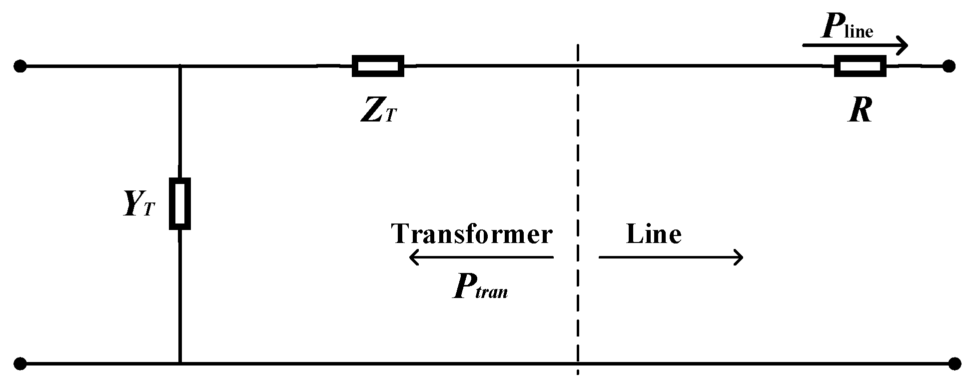
Figure 1. The equivalent models of transformer and line.
Processes 08 00559 g001
Figure 2. The main idea of an improved bat algorithm based on non-dominated sorting (NSIBA).
Processes 08 00559 g002
Figure 3. The main idea of elite strategy.
Processes 08 00559 g003
Figure 4. The flowchart based on a two-layer optimization model.
Processes 08 00559 g004
Figure 5. The structure drawing of a distribution network.
Processes 08 00559 g005
Figure 6. The convergence property for OFs of NSIBA and other methods; (a) minimum network power loss, (b) minimum voltage stability margin, and (c) total cost of investment and operation.
Processes 08 00559 g006
Figure 7. Pareto optimal fronts: (a) three-dimensional diagram, (b) vertical view, (c) vront view, (d) end view.
Processes 08 00559 g007
Figure 8. The typical daily characteristic curves of load, photovoltaic, and wind power.
Processes 08 00559 g008
Figure 9. Voltage in different scenarios: (a) Scenario 1 (b) Scenario 2 (c) Scenario 3.
Processes 08 00559 g009
Figure 10. The voltage and current amplitude of each node.
Processes 08 00559 g010
Table 1. Comparative important scale of criteria.
ScaleMeaning
1Two factors are equally important
3One factor is weakly important than another
5One factor is strongly important than another
7One factor is demonstrably important than another
9One factor is absolutely important than another
2, 4, 6, 8The median of two adjacent judgments
Table 2. Analysis of economic optimization configuration of an expansion-transformed energy storage system.
ScenarioBusesRetrofit SchemeCost ($)Revenue Expense ($)
G1G2G3G4
transformer expansion7,17,22,25315 kVA to 500 kVA2076.9311.0866857.14/−8945.16
ESSs7,17,22,257(0.3319 MWh)2072.5411.08762,018.5766,714.202612.22
17(0.2571 MWh)
22(1 MWh)
25(0.6477 MWh)