1. Introduction
Near net shape casting (NNSC) processes can be regarded as an ideal method for metal sheet production. Apart from their low energy requirements, lower capital and operating costs, and smaller plant footprints than those associated with slab casters (Fe), and DC casters (Al), they also have promising metallurgical characteristics associated with much higher cooling rates possible [
1,
2,
3,
4,
5]. However, they can also have drawbacks, regarding surface quality, which conventional plants can overcome, by scarfing and multi-pass rolling, to the final quality strip [
6]. An advantage of NNSC processes is that a homogenous microstructure with almost zero macrosegregation and fine grain sized products can be attained, provided cooling rate conditions are met, as the cast product’s dimensions approach the desired sheet specifications [
4].
Therefore, fewer hot/cold reduction passes are required as opposed to conventional methods i.e., slab, or thin slab, casting (TSC) of steels, or direct chill (DC) casting for aluminum alloys. This undoubtedly brings down the overall cost of the operation. On the other hand, the high surface area-to-cast thickness is much higher (~100×), making surface oxidation more problematic, as well as surface quality and surface dimensions [
3]. The three most commonly used NNSC processes, commercialized to date, are the twin roll casting (TRC), the earlier twin belt caster, and, most recently, the single belt caster [
6]. Historically, the commercialization of the Hazelett twin belt caster in the 1930s by Clarence Hazelett, was an early breakthrough for NNSC. It has since been used around the world, ever since, for casting non-ferrous alloys, mainly aluminum, copper, and zinc, down to cast thicknesses of 13–21 mm [
7]. All attempts with steel have failed.
As the name suggests, TRC utilizes two contra-rotating water-cooled rolls, onto which the molten metal is fed and cast as a thin strip. Invented by Henry Bessemer back in 1857 [
8], and despite extensive research and development activities that followed, the world’s first strip caster for aluminum was only commercialized in 1954, approximately 100 years after Bessemer’s initial idea. Currently, FATA Hunter and Novelis PAE (previously SCAL-Pechiney) are leading companies manufacturing TRC equipment for aluminum strip production [
9]. The cast strip thickness is almost 6 mm. The first TRC strip caster commercialized for steel was by Nippon Steel and Mitsubishi Heavy Industries Corporation in 2000. The caster could produce stainless steel strips, 2–5 mm thick, 0.76–1.5 m wide, in NSC’s Hikari Works in Southern Japan, but was not a commercial success and was abandoned. Later, in 2002, NUCOR started the production of a low carbon steel strip, 1.7–1.9 mm thick via a TRC process, CASTRIP, and this continues to operate, commercially [
6]. However, TRC, though a proven aluminum/steel strip manufacturing process, suffers from low annual production of steel vs. that of a conventional slab casting process, i.e., 400,000 tpy and 2,000,000 tpy, respectively [
10].
An Introduction to Horizontal Single Belt Casting (HSBC) Process
The horizontal single belt casting (HSBC) process, independently conceived by Herbertson, Guthrie, Reichelt, and Schwerdtfeger, et al., emerged from a joint effort of BHP (Australia), McGill University (Canada), and the Hazelett Strip Casting Corporation (USA) as discussed above. This process is like the Pilkington float glass technology, in which the molten glass is continuously poured over a bath of molten tin where it solidifies into a continuous glass sheet [
5].
The HSBC process avoids the multi-hot rolling-deformation steps required for direct chill (DC) cast material, together with its intermediate annealing steps, while producing the same desired final thicknesses of sheet products. As such, a large amount of energy can be saved. This is essentially true for all NNSC processes discussed above. The HSBC process features a compact design and provides for the better economic production of both ferrous and non-ferrous metallic products. The production of advanced high-strength steel (AHSS) strips, 16 mm thick, via the HSBC process at Salzgitter Group Steelworks, Germany, is an example that makes use of the advantages that the HSBC process offers, vs. conventional strip manufacturing processes. To date various ferrous/nonferrous alloys strips, up to a thickness of 16 mm, were successfully produced. For further reading, please refer to the available literature [
11,
12].
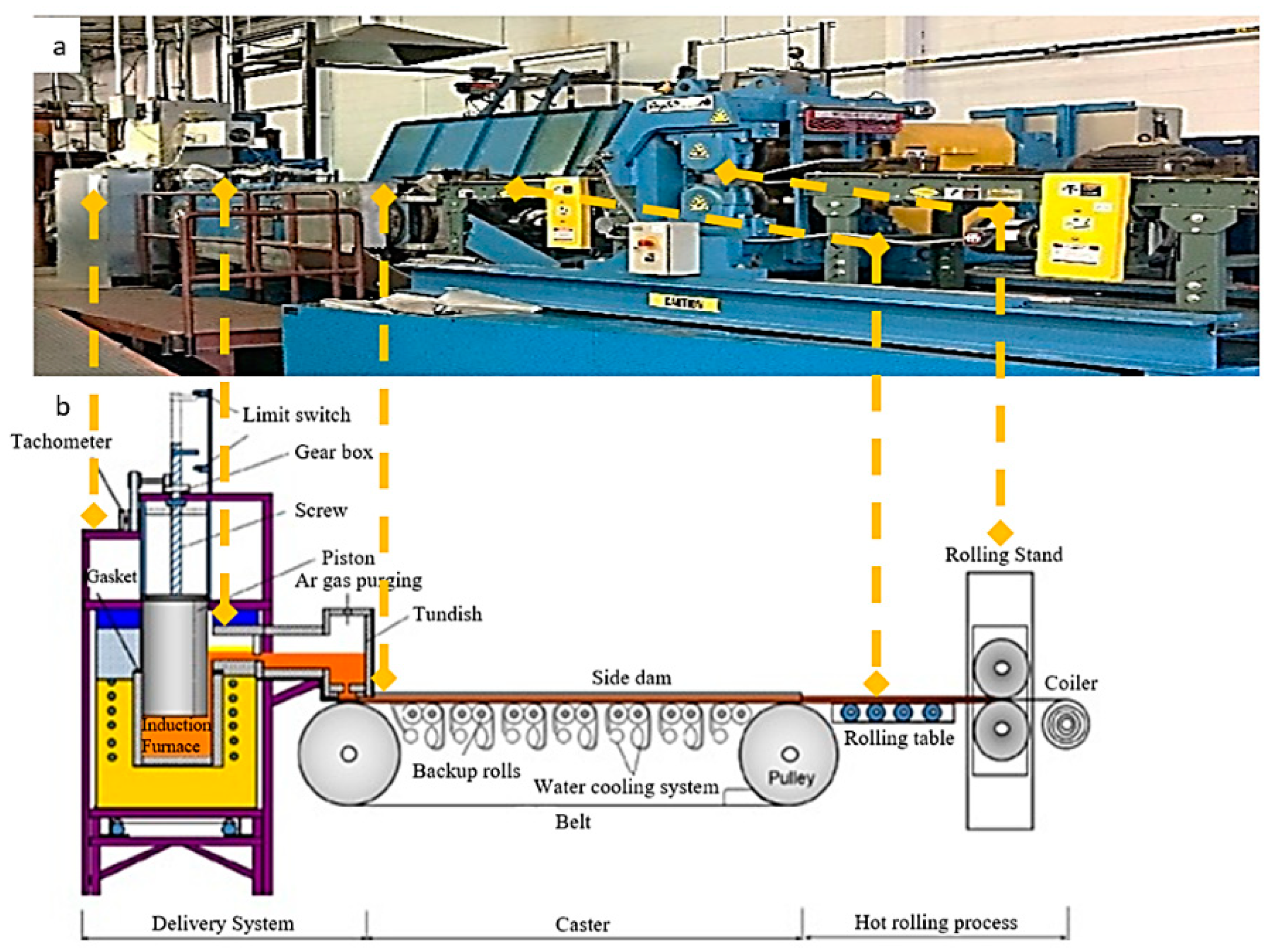
Simplistically, the HSBC process involves feeding molten metal on to an intensively cooled, moving belt, which acts as the mold. Depending on the metal head in the launder, the velocity of the molten metal issuing from the slot nozzle can be easily adjusted. However, the force of gravity is also equally responsible in further accelerating the molten metal before it contacts the moving belt, on which it solidifies [
13,
14,
15]. The material produced via the HSBC process can then be processed downstream, by hot rolling, followed by cold rolling, as shown in
Figure 1.
2. An Overview of Previous Studies Conducted on HSBC Metal Feeding Systems
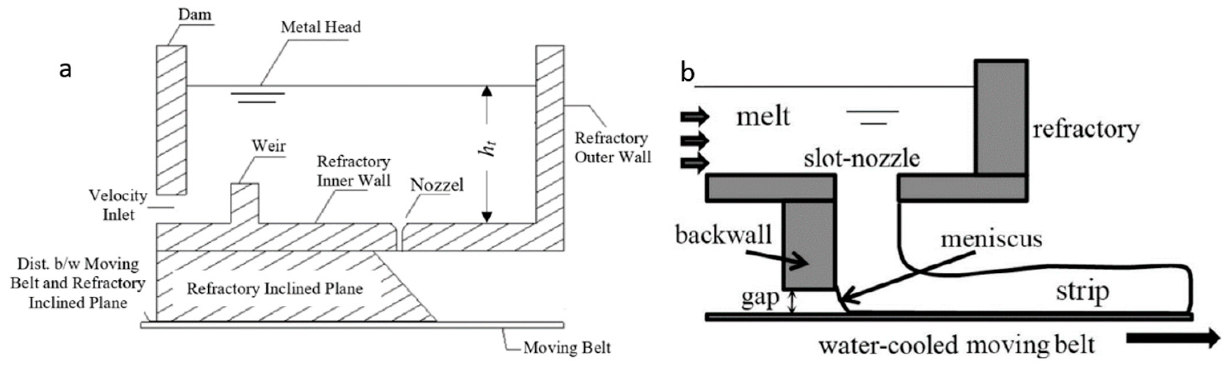
Many variants of the feeding system have been investigated by researchers at McGill Metals Processing Centre, to date. They can be classified into two types of the metal delivery systems; either single-impingement or multi-impingement, based on how many times the molten metal encounters obstacles before reaching the cooling substrate, as shown in
Figure 2 [
2,
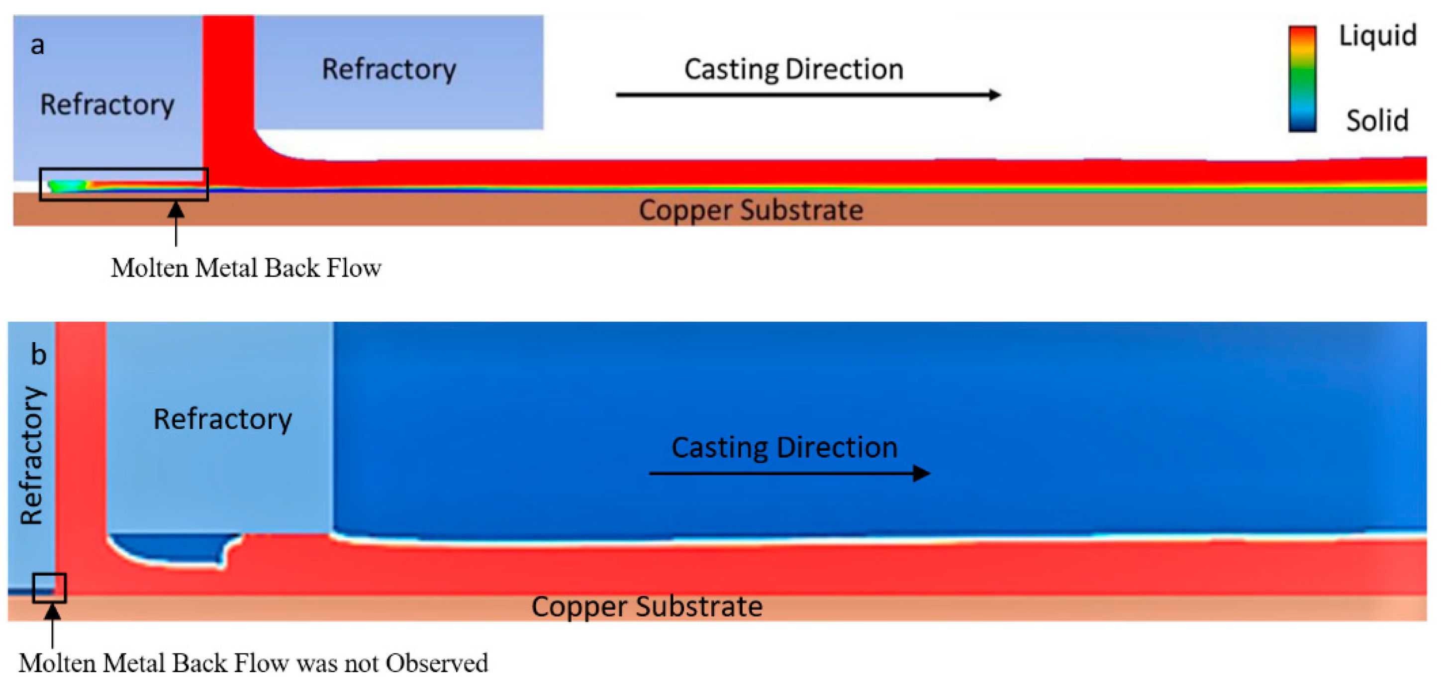
3]. In a single impingement feeding system, the molten metal is abruptly stopped by the horizontally moving belt, since there is no intermediate obstacle in its way, which could decrease its kinetic energy. As a result, the molten metal tends to penetrate back into the quadruple region, i.e., the region where melt, refractory, air, and belt coexist, as determined by Sa Ge et al. [
3], for the casting of plain carbon steel, employing a single impingement feeding system (
Figure 3a) [
3]. If the backflow is too excessive, it may lead to skull formation, thereby curtailing further casting as determined experimentally.
Additionally, it has been shown by Sa Ge [
13], that a single impingement feeding system can be used to produce Al-Mg-Sc-Zr alloy strips, without any backflow into the quadruple region (see
Figure 3b), as was found for steel casting. This could be due to the low density of Al-Mg-Sc-Zr alloy and a higher contact angle, i.e., a lower wettability between liquid Al-Mg-Sc-Zr and the alumina refractory [
13].
In both these studies, the molten metal flowing over the moving belt was considered as being nearly iso-kinetic, a condition in which the velocities of the molten metal and belt approach each other. Furthermore, the as-cast thickness of the produced strips was ~3 mm [
3,
5].
As explained above, excessive backflow of molten metal into the quadruple region is not desired. This can be conveniently prevented by employing a double-impingement feeding system in the HSBC process [
14]. In a double impingement feeding system the molten metal dispensing from the refractory nozzle slot first interacts with a 45° inclined refractory plane, followed by its second interaction with the moving belt, on to which it begins to solidify [
14]. In this way, the final impact of the molten metal with the moving belt is not as rapid and abrupt, as it would be for a single-impingement feeding system [
4]. Furthermore, in a double-impingement feeding system, the flow of the molten metal over the inclined refractory plane and the moving belt is entirely gravity-driven, unlike the variant of the single-impingement feeding system reported by Sa Ge for the casting of Al-Mg-Sc-Zr. For that, the flow of the molten metal is impeded by the refractory front wall, as shown in
Figure 3b [
13]. During continuous operation, the refractory material may abrade and embed small particles into the pool of molten metal. This could significantly decrease the bulk quality of the cast strip.
In this research study, non-isokinetic feeding of molten metal over the moving belt has been considered. This is significantly different from our group’s previous research studies, for which only near iso-kinetic feeding was considered, as discussed above. Under non-isokinetic feeding conditions, as in the present case (the belt/side dam speed is considerably slower, i.e., 0.3 m/s, as compared to the molten metal velocity at the nozzle slot outlet, i.e., 2 m/s). The strip produced under this condition has ~6 mm thickness, which is thicker as compared to the strips obtained under iso-kinetic feeding (~3 mm). This allowed us to perform substantial hot deformation in order to produce a 1 mm, or lower, thickness of strip. Hot deformation is necessary, as it transforms the cast dendritic structure into fine equiaxed grains, leading to a far more uniform distribution of alloying elements throughout the sheet material. Another purpose of hot reduction is to squash/weld any pores, if present, in the cast strip, so as to improve its mechanical properties [
15].
3. Objectives of the Present Research
The objective of this research study is to produce high-quality AA6111 aluminum alloy strips 250 mm wide, ~6 mm thick. Additionally, molten metal flow in a double-impingement feeding system has been analyzed under non-isokinetic feeding. Under these experimental conditions, the molten metal was observed to be flowing inwards, i.e., towards the center of the strip. This can usefully eradicate center shrinkage cavity defects formed otherwise. In order to investigate this phenomenon, a three-dimensional mathematical model was developed using Fluent software (14.5, Ansys, Inc., Canonsburg, PA, USA, 1970), and its accuracy was evaluated against experimental data. Thanks to these numerical simulations, we now understand the complex interaction of the molten metal with the inclined refractory plane and the moving belt that leads to the phenomenon of the molten metal’s inward flow.
A horizontal single belt pilot caster installed at MetSim Inc., Montreal, QC, Canada, was used for the casting experiments. However, several modifications were applied to the existing caster, as it was not capable of producing 250 mm wide strips. These included the design of a new alumina refractory nozzle slot (250 mm wide and 3 mm thick), increasing the cooling capability of the moving steel belt, needed to completely solidify molten AA6111 strip before it exits the moving belt. Additionally, the caster modifications included enlarging the strip guidance system, and, lastly, the extension of the length and width of the run-out table, so as to accommodate the wider strip exiting the caster.
4. Aluminum Alloy Grade, AA6111, Used in the Present Research
Keeping in mind the suitability of the HSBC process to cast both ferrous and non-ferrous alloys, and knowing the usefulness of AA6111 aluminum alloy in the production of the lightweight body in white (BIW) automotive structures, AA6111 was selected for HSBC strip production. AA6111 is an alloy of Al-Mg-Si (Cu). It possesses higher mechanical strengths (i.e., 400 MPa), high formability, and good corrosion resistance. The main mechanism behind AA6111′s increased strength is precipitation hardening, along with the solid solution and work strengthening [
16,
17]. The alloying elements present in AA6111 are as shown in
Table 1.
The casting of AA6111 strips via the HSBC process is comparatively new, and is presently in its development stages. It is, therefore, hoped that this paper will add fundamental knowledge to the information already existing on this subject, and help industries realize the versatility of the HSBC process to cast AA6111 aluminum alloy strips.
5. Details of the Experimental Procedure
AA6111 alloy was produced by first melting pure aluminum in a pre-heated induction furnace under a protective argon atmosphere, followed by the addition of Al-Mg, and Al-Mn alloys, etc. Good melt stirring was used, to ensure completely dissolved/mixing of the alloy additives into the pure aluminum. The melt was then de-gassed and Ti-B grain refiner was added in a conventional way. The AA6111 melt was then cast into the strips using the HSBC system. The step-by-step operation of the HSBC pilot caster is presented below.
The process started with the production of AA6111 alloy using the 600 lb induction melting furnace. Afterwards, the furnace was moved on rails to the casting station, where it was locked with the liquid metal delivery system. This consisted of a refractory cylinder (regulated by a servo motor) and a launder, as shown in
Figure 1. Once the tight seal between the induction furnace and delivery system was ensured, the motorised refractory cylinder was allowed to enter into the induction furnace at a pre-selected speed, thereby displacing the molten metal into the launder. Once the molten metal reached the desired level within the launder, the stopper bar blocking the nozzle outlet was rapidly withdrawn, and liquid metal began to pour onto the belt. A weir and a dam were used to help prevent Al
2O
3 oxide skin from entering the nozzle slot, as well as to help in minimizing turbulence present within the flowing molten metal. The moving belt could also be equipped with two rotating side dams. Their purpose was to contain the molten metal once it leaves the nozzle slot, and to give a straight/smooth edge before it enters the minimill for hot reduction. To avoid any premature freezing, the entire delivery system and the refractory piston were preheated to approximately 500–550 °C, using electrical resistive heating systems.
To evaluate the bulk, as well as the surface, quality of the cast strips, samples were sectioned from the strip. All samples were polished and prepared for metallographic observations and analyzed under Leica DM IRM optical and Hitachi TM3030 scanning electron microscope. The surface roughness was measured using a 3D Nanovea profilometer. Results will be presented in later paragraphs.
6. Details of the Model Setup
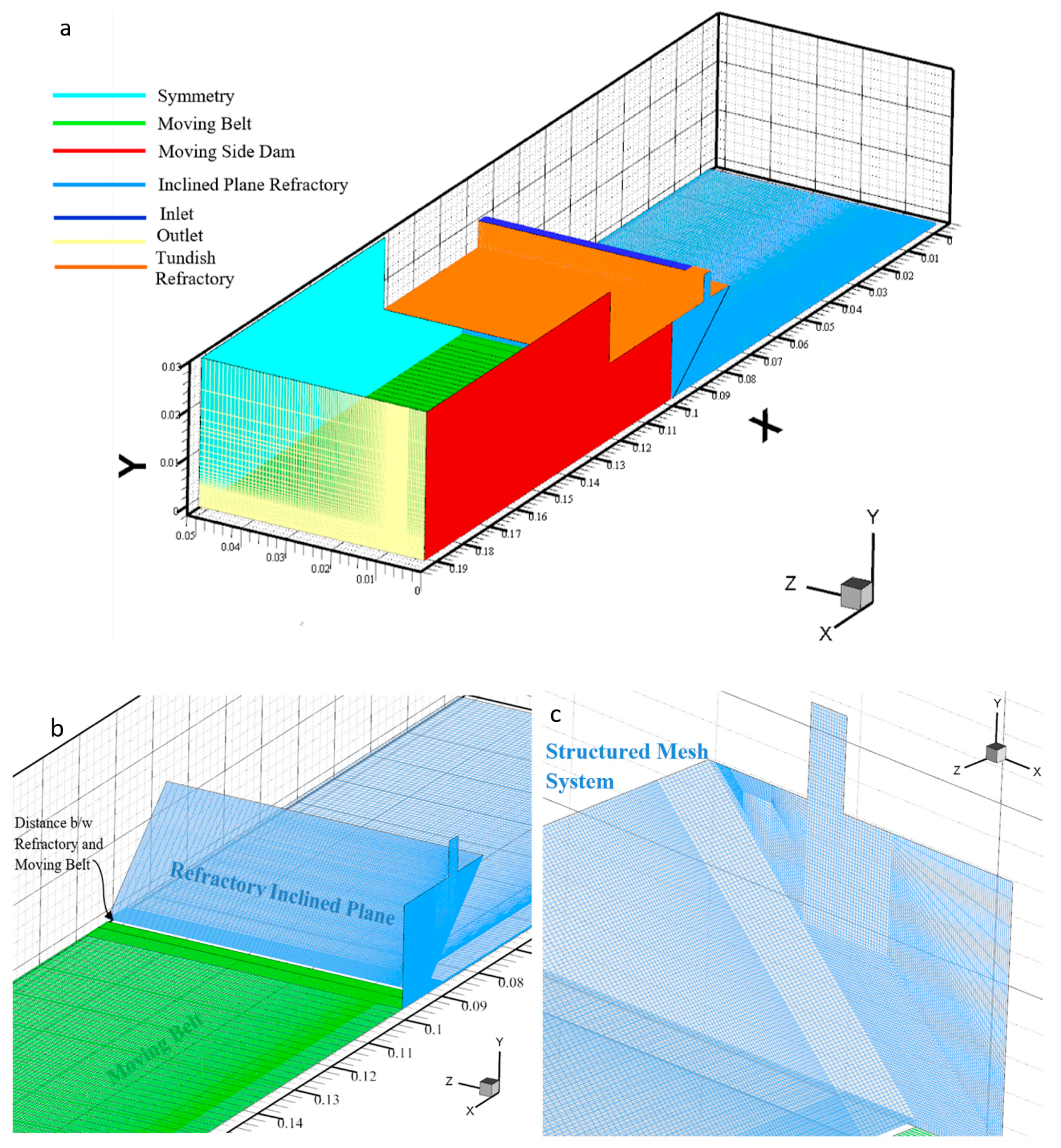
For CFD studies, the three-dimensional, transient state, turbulent fluid flow was modeled using Fluent software (14.5, Ansys, Inc., Canonsburg, PA, USA, 1970). The code is based on the finite volume method (FVM) [
18]. The simulation domain chosen to carry out this research study had the following dimensions, length (0.195 m), height (0.016 m), and width (0.05 m), as shown in
Figure 4. The semi-implicit method for pressure linked equations (SIMPLE) was used for coupling pressure and velocity in the governing equations. More details can be found in the literature [
19]. To improve on the accuracy, the advection terms were discretized using a 2nd-order upwind scheme over the entire simulation domain, whereas the diffusion term was approximated by the central differencing scheme. To stabilize the interactive process, an under-relaxation factor of 0.7 for the velocity and 0.3 for the pressure, were used. The solution process was iterated until the residuals of governing equations reduced to
. Different grids were tested until mesh-independent results were achieved. Finally, 2,867,541 hexahedral cells were identified as being an accurate, but less computationally intensive, exercise for obtaining the desired results. The molten metal was treated as a Newtonian, incompressible fluid, and all the physical properties were assumed to be constant (
Table 2 and
Table 3).
7. Results and Discussion
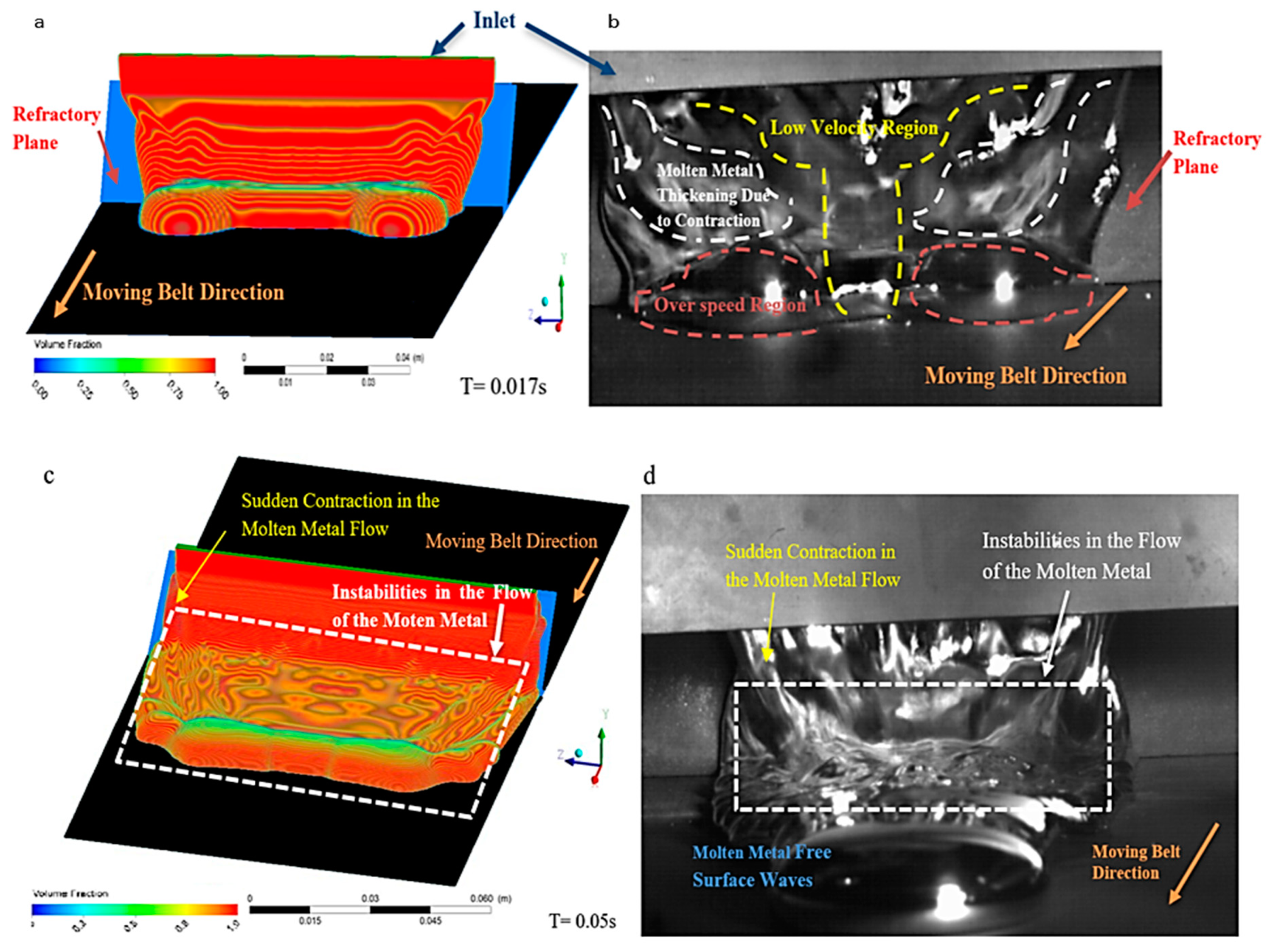
It was observed through numerical simulation studies that in the HSBC process, the molten metal tends to laterally contract/shrink while exiting through the nozzle slot outlet, as shown in
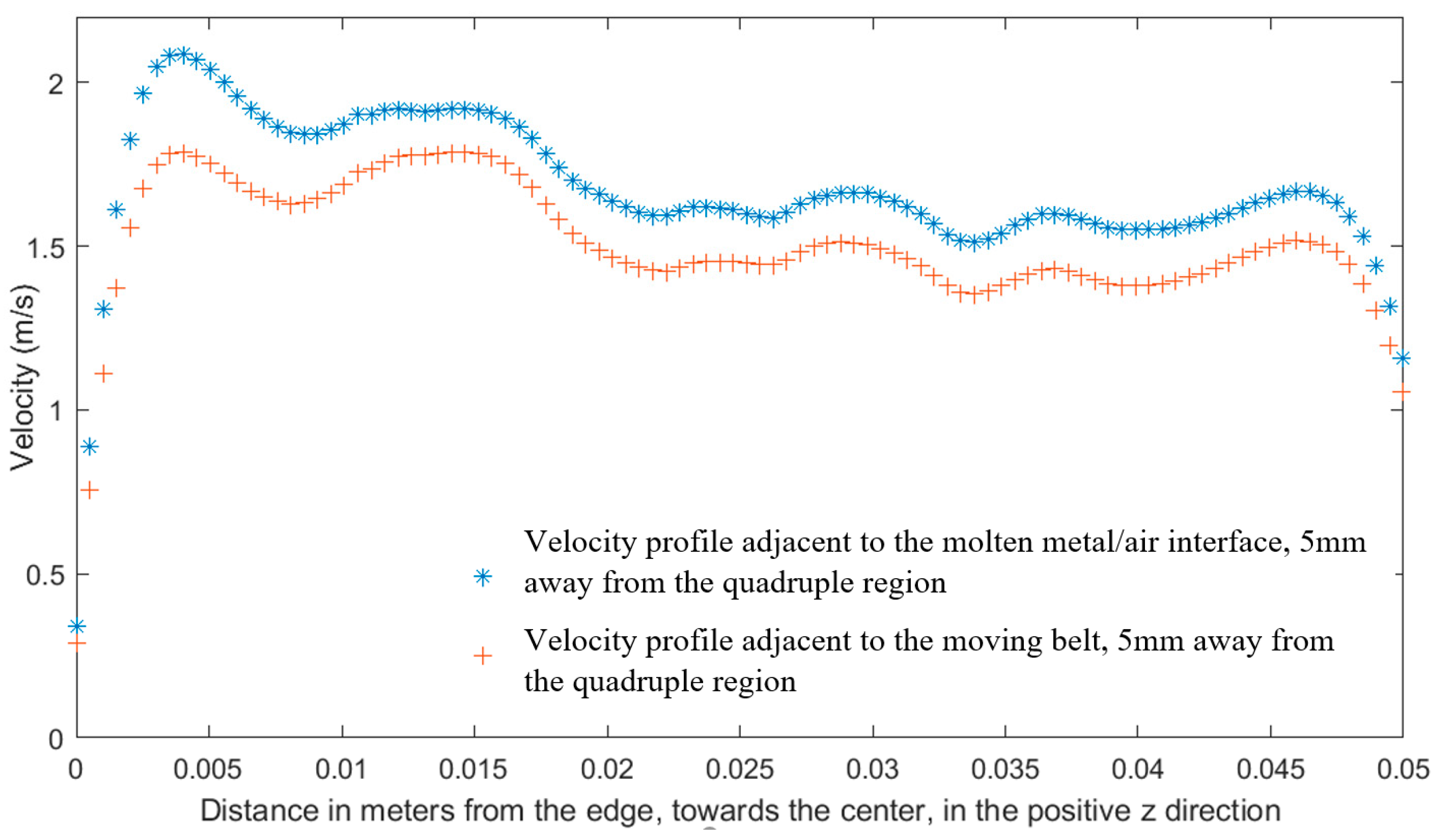
Figure 5. Due to this lateral contraction, the weight of the molten metal around the edges increases considerably as compared to the center. The heavier section accelerates downwards under the influence of gravity, eventually reaching a high terminal speed before it strikes the moving belt. This concept is further explained by plotting molten metal velocity, adjacent to the free molten metal/air interface and the moving belt, against distance in the positive z-direction. As expected, the magnitude of the velocity around the edges, for both cases, is high as compared to the center. These velocities are computed 5 mm away from the quadruple region (down the ramp), as shown in
Figure 6.
Additionally, it has been observed that the velocity of the molten metal adjacent to the moving belt is lower than the velocity at the free molten metal/air interface, as shown in
Figure 6. This is due to the friction offered by the moving belt, which tends to slow down the velocity of the molten metal adjacent to it.
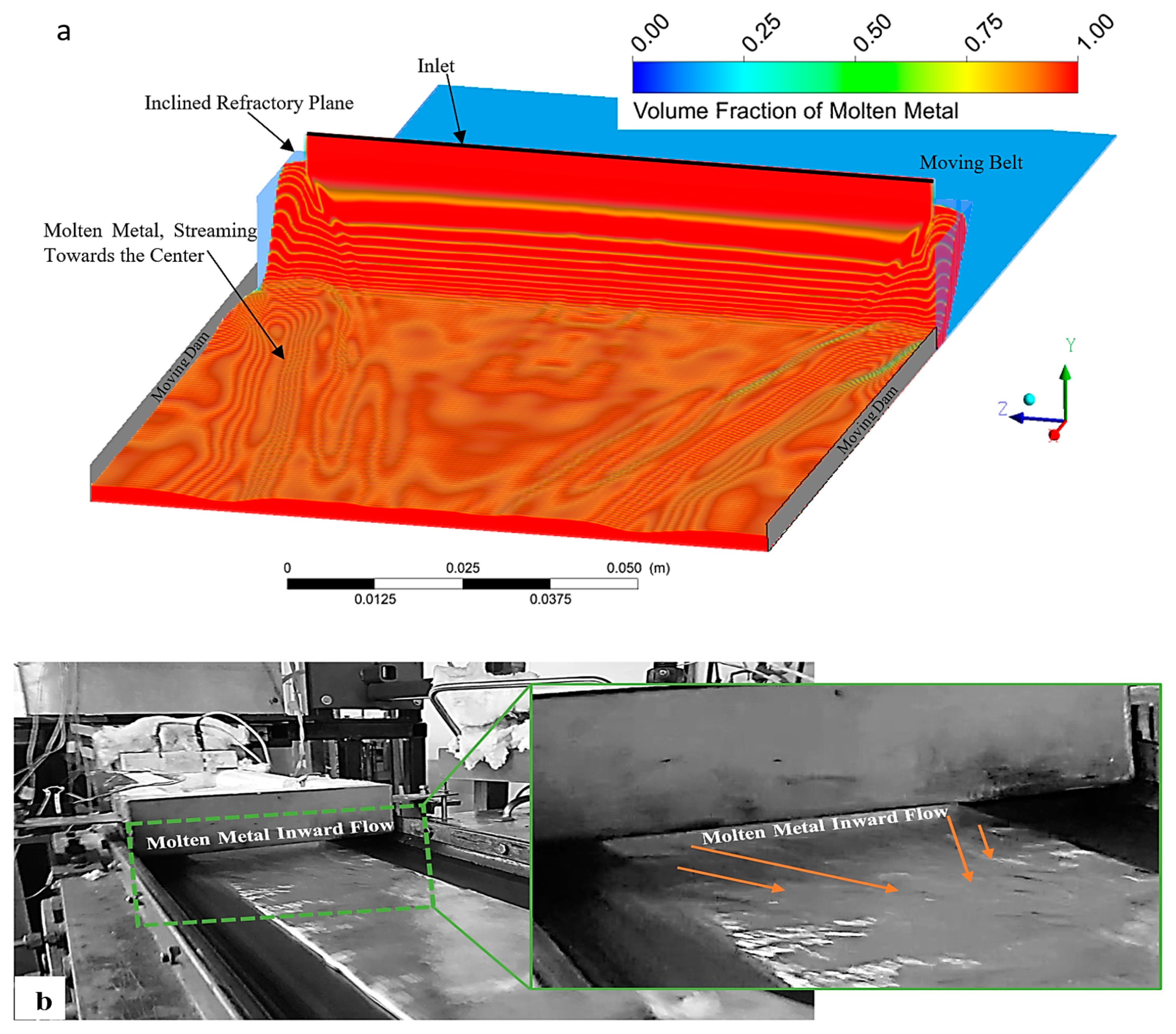
Based on the above discussion, it can be concluded that the amount of molten metal, delivered towards the edges, is considerably greater in comparison to the center, as shown in
Figure 5a,b, owing to the initial contraction/shrinkage of the molten metal while exiting through the slot nozzle outlet. The net effect is an inward flow of the molten metal towards the center, as shown in
Figure 7. This inward flow can be very beneficial, as it eradicates the center shrinkage cavity defect, formed otherwise, at low metal heads in the launder. This topic is further explained in the following paragraphs.
7.1. Method to Eradicate Center Cavity Defects
As discussed above, in the HSBC process, employing a double impingement feeding system, the molten metal streams towards the center. Keeping in mind that at lower metal heads (<50 mm), the quantity of the molten metal delivered onto the moving belt is also low, as per Equation (1). As observed experimentally, under the rapid heat extraction rate to the moving belt (i.e., 500 K/sec) [
3], the molten metal passing over the moving belt, tends to solidify almost instantaneously. Since the molten metal does not have enough time to level off before the completion of solidification, this results in a strip with a thicker edge, and a comparatively thinner center.
The opposite is true for high metal heads inside the tundish (>50 mm). In this case, the velocity of the molten metal exiting the refractory nozzle slot outlet is high enough to trigger a strong net inward flow. Under these conditions, the molten metal will have enough time to fill the center empty region and to evenly spread throughout the thickness of the strip before the completion of solidification. This helps to eliminate any center cavity defect and to achieve a uniform thickness of the strip across its width.
where V is the velocity, h is the molten metal head inside the tundish, and
is the coeffecient of discharge.
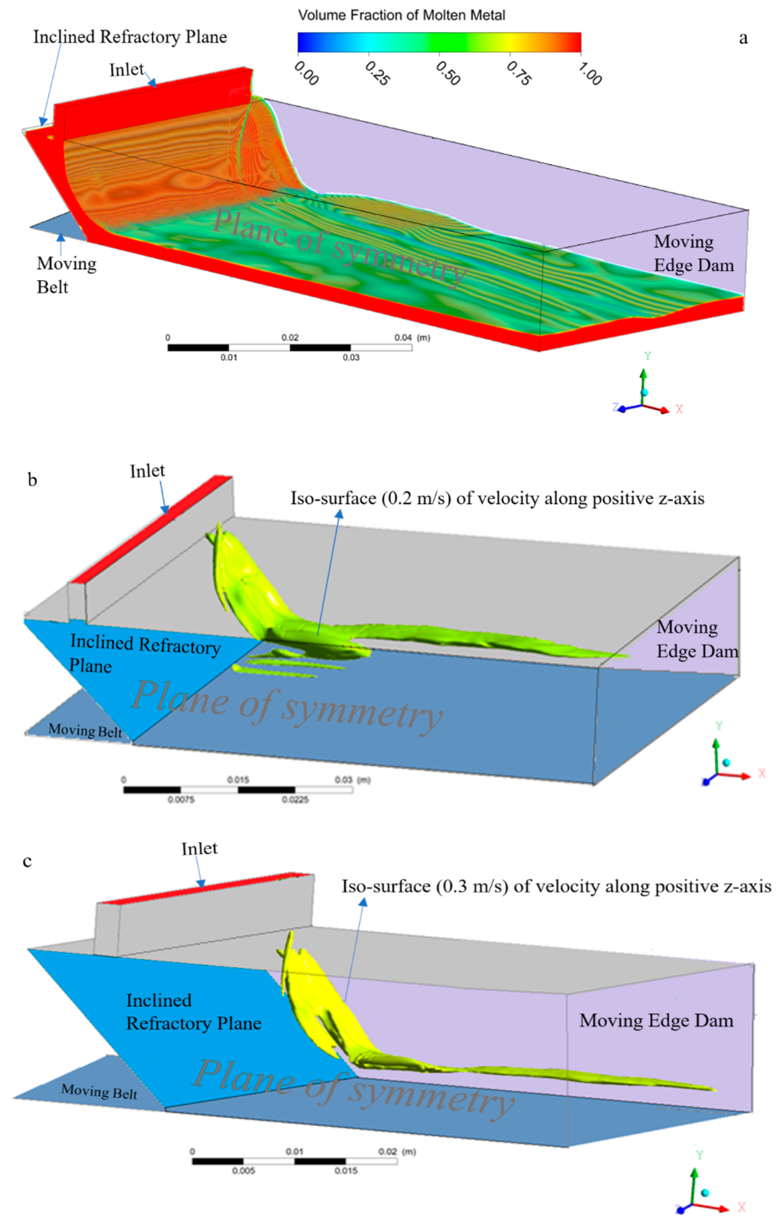
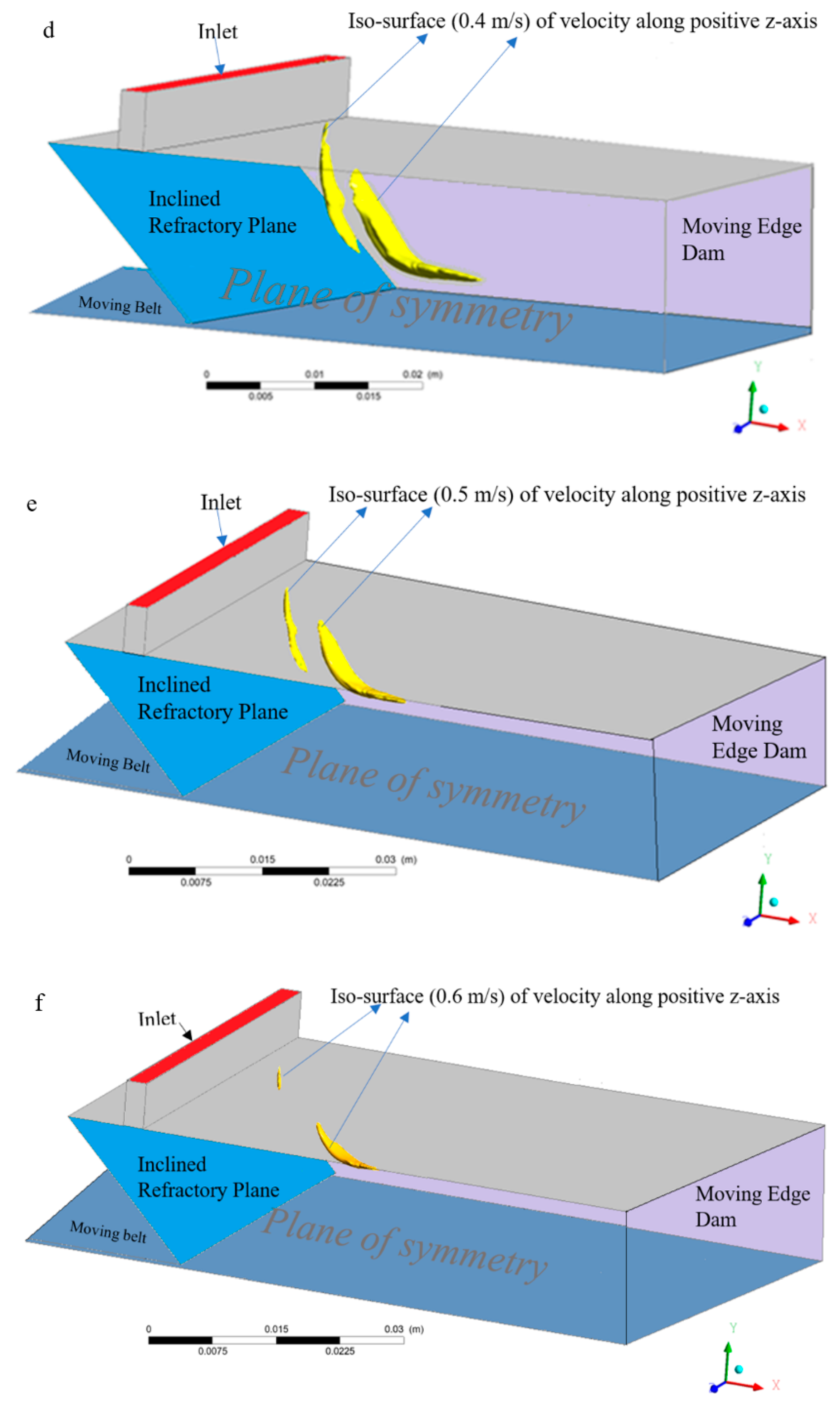
7.2. Iso-Surfaces of Z-Component of Velocities
The velocity vector can be resolved into three components, i.e., x, y, and z in which the z-velocity component represents a net inward flow of the molten metal. For these reasons, the isosurfaces of the z-component of the velocities were evaluated and are represented in
Figure 8.
As expected, the z-component of the velocity vector is maximal during the first instants of the molten metal contacting the moving belt, owing to the fact that molten metal, while flowing over an inclined plane, continuously accelerates under the force of gravity. Furthermore, the z-component of velocity was observed to be high adjacent to the molten metal/air interface, and almost zero near the moving belt. However, further downstream, over the belt, the z-component of velocity was observed to be decreasing with distance. This is essentially true, as there is no driving force that could help the molten metal to further accelerate over a horizontal moving belt.
7.3. Casting of AA6111 without the Use of Side Dams
The friction imposed by a slowly-moving belt reduces the velocity of the molten metal over the moving belt. As a result, the molten metal tends to spread outwards, as shown in
Figure 5c,d. However, adjacent to the free interface, the flow of the molten metal is directed towards the center, as is evident from the z-component of iso-velocities presented above. Depending on the relative magnitude of these two opposing effects, the molten metal can either flow towards the center, or outwards.
However, by looking at
Figure 7, it can be clearly seen that the molten metal is flowing towards the center. This is very beneficial, as it eliminates the need for side dams to control the outward flow of the molten metal. The successful casting of the AA6111 strip (
Figure 7b), without the aid of side dams (See
Figure 7), experimentally, verifies the numerical modeling predictions.
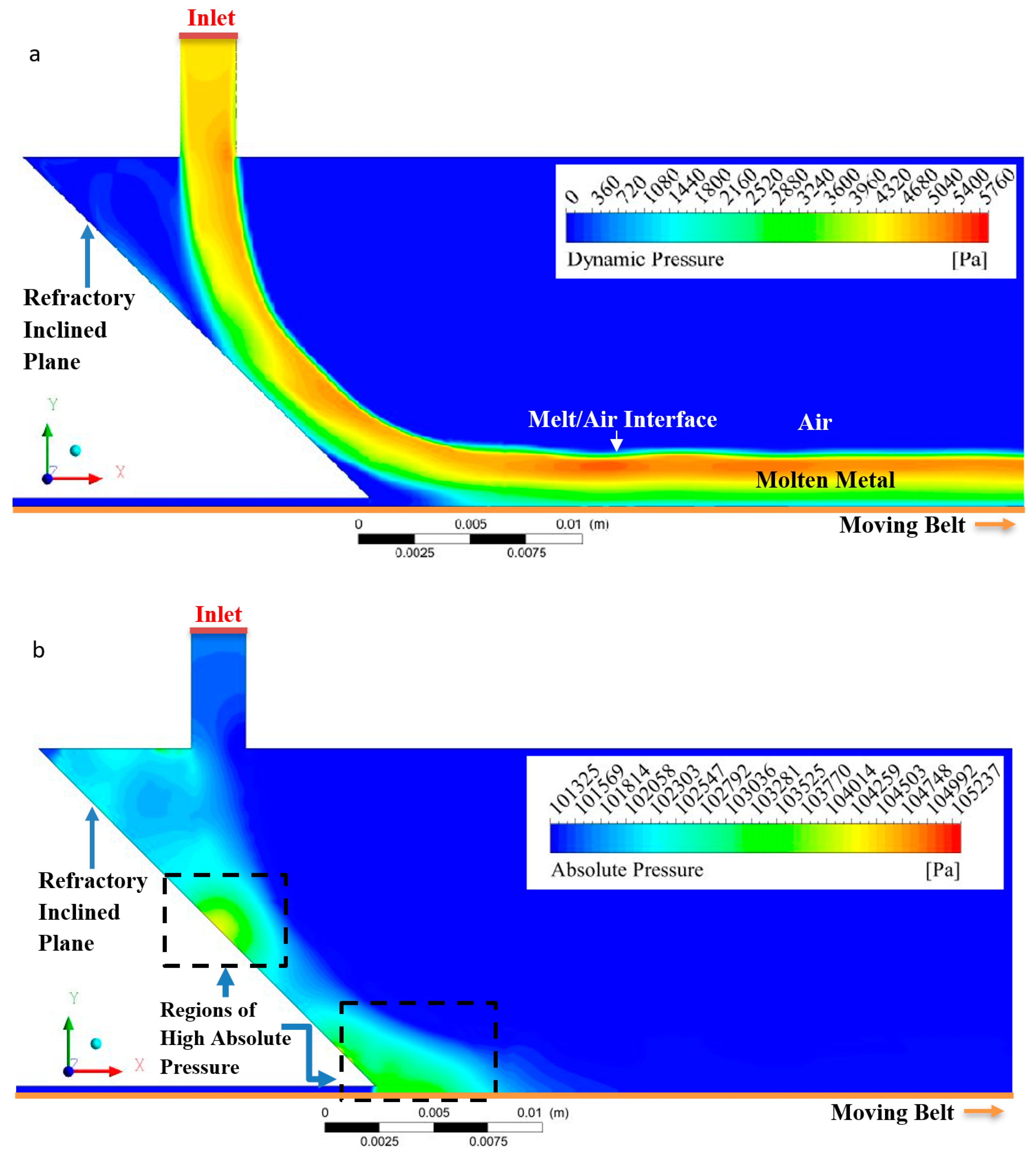
7.4. Pressure Distribution of Molten Metal and the Generation of a Vortex Near the Triple Point
It is observed via the numerical simulations, that the inclined refractory plane has the tendency to lessen, or moderate, the final impact of the molten metal on to the moving belt, by converting a part of the molten metal’s kinetic energy into static pressure, as presented in
Figure 9b.
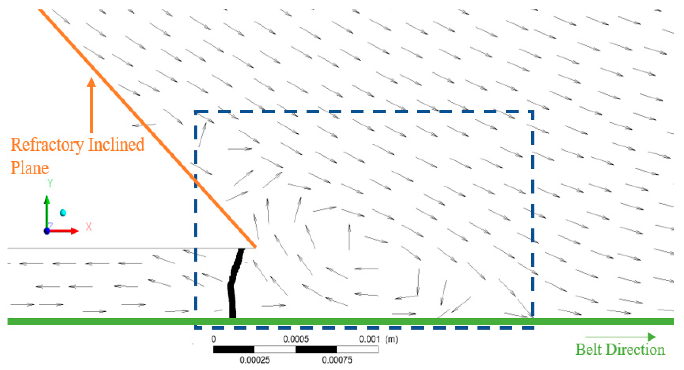
Additionally, the numerical simulations predict a considerably higher absolute pressure (low velocity) near the quadruple region (
Figure 9b), due to sudden decrease in velocity of the molten metal by a slow-moving belt. This results in a part of the impinging molten metal climbing upwards, forming a vortex, as shown in
Figure 10. Furthermore, the dynamic pressure, i.e.,
is observed to be highly adjacent to the molten melt/air interface. This result is due to the high velocity of the molten metal near the free surface, as shown in
Figure 9a.
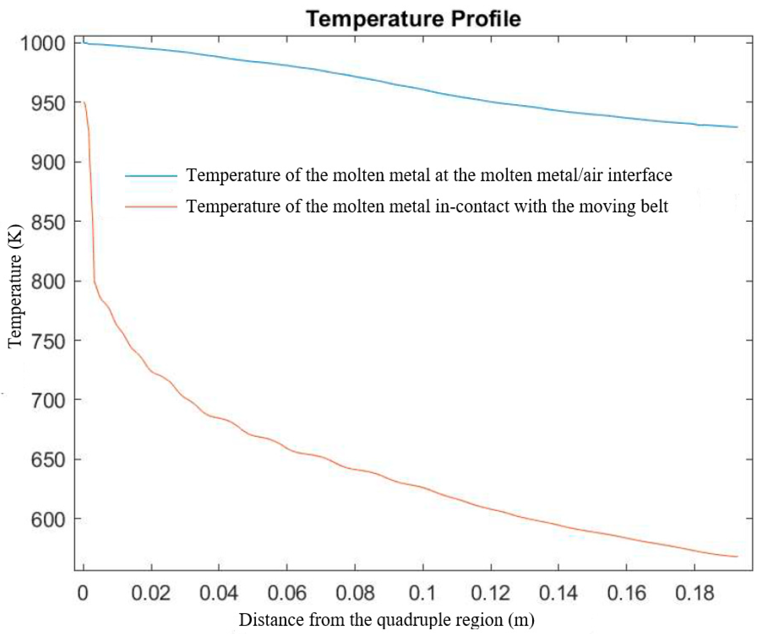
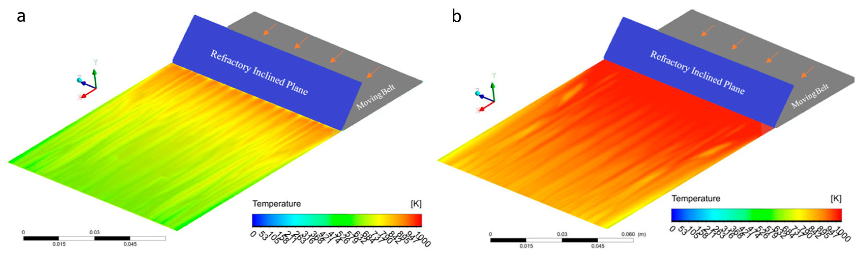
7.5. The Temperature of the Molten Metal at the Melt/Air Interface
The hydraulic jump on the inclined refractory plane could substantially degrade the surface quality of the cast product, owing to the generation of free surface waves/discontinuities [
14]. As per the numerical simulations, the temperature over of the melt/air interface is above the liquidus for a considerable distance, as shown in
Figure 11 and
Figure 12, even when considering perfect contact of molten metal with the moving belt, which is held constant at 300 K, by the cooling water under the belt. The experimental casting of the AA6111 alloy strip was in accord with numerical simulation predictions, in which the melt/air interface with the belt was observed to be in a liquid state for approximately the first meter along the moving belt. In this way, any molten metal surface discontinuities had enough time to settle down by the damping forces generated, before final solidification.
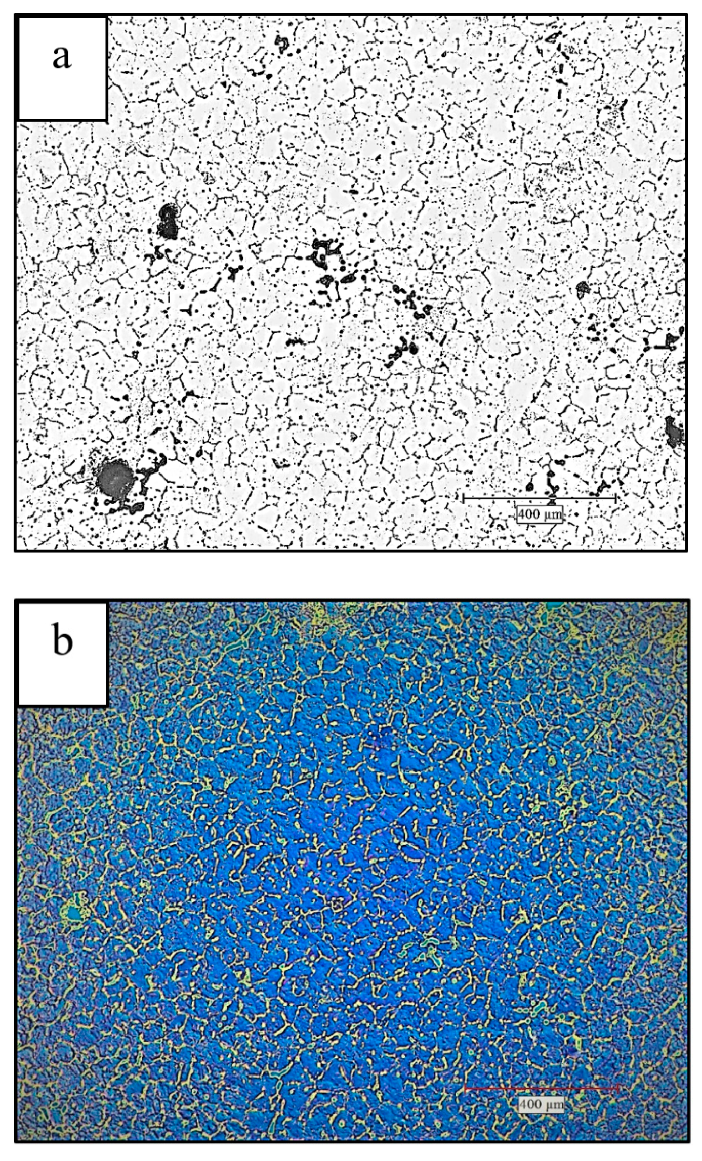
7.6. Characterization of the AA611 Alloy Cast Strip
A microstructural study has been carried out to analyze the quality of the cast strips. The samples for optical microscopy were ground down to 1200 grid, and then electropolished/etched using 2% perchloric acid (HClO
4) in alcohol. Micro images were taken using a Leica DM IRM optical microscope (Leica Microsystems, Concord, ON, Canada) and a TM3030 Scanning Electron Microscope (Hitachi, Pleasanton, CA, US). The microstructure consisted of fine equiaxed grains throughout the thickness of the strips (see
Figure 13). The microstructure also contains porosities at various locations within the cast strip, very similar to DC cast product. The average grain size of the strip was found to be 85 μm, as shown in
Figure 13.
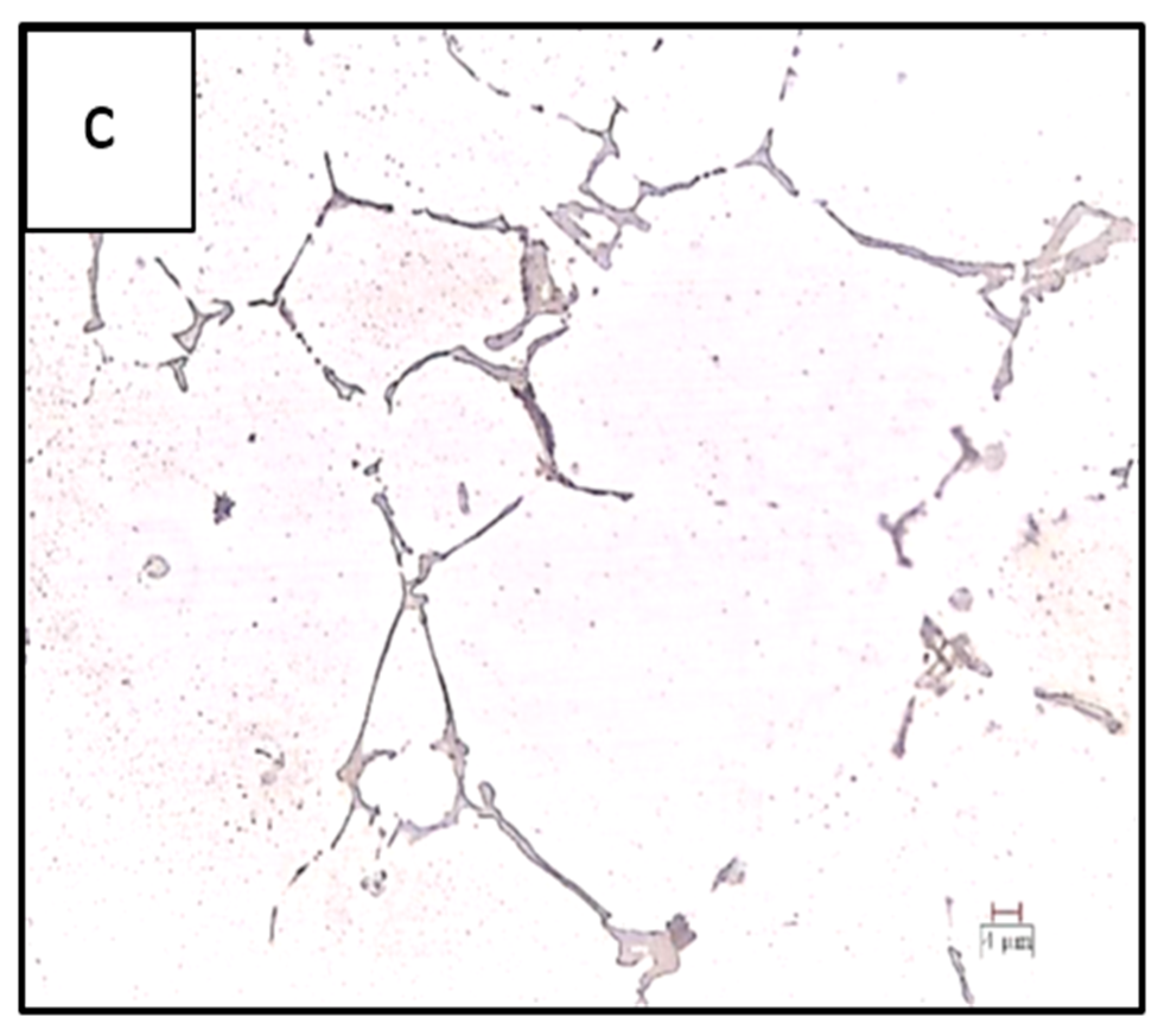
The inter-metallics are also observed to be distributed inside the grains, as well as at the grain boundaries of the cast microstructure, as shown in
Figure 13c. X-ray micro-analyses revealed that inter-metallics dispersed throughout the cast structure have the following stoichiometry: Al
17Cu
2Mg
3Si
3, Al
20Cu
2Mg
2.5Si
5, whereas the elongated inter-metallics distributed at the grain boundaries are in the category of Al
17(CuMg)
2(FeMn)Si
2 or Al
25(CuMg)
4.5(FeMn)Si
5 [
16,
17]. These phases are clearly observed in the
Figure 13c, at a higher magnification of 500×.
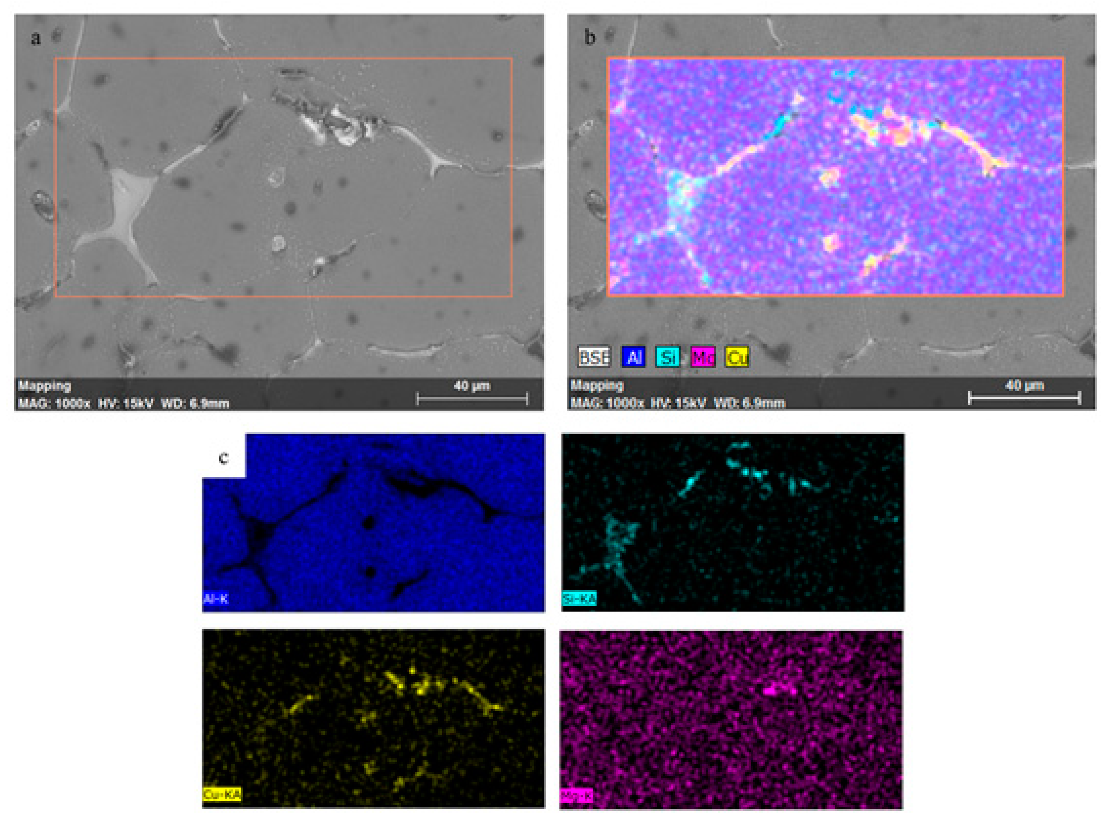
7.7. Energy Dispersive Spectroscopy (EDX) Analysis of the Cast AA6111 Alloy
Energy dispersive spectroscopy (EDX) analysis confirmed the presence of Al, Cu, Mg, and Si, in AA6111 alloy, as shown in
Figure 14. Furthermore, there is a negligible macro-segregation of alloying elements in the cast strip, as shown in the chemical element’s maps, obtained at 15 KV excitation voltage. This is caused by the rapid solidification of molten AA6111 alloy in the HSBC process, which resulted in a homogenous microstructure with fine equiaxed grains. Additionally, the elemental maps provide us with details of the chemical nature of the secondary phases. EDX analyses revealed that inter-metallics dispersed throughout the cast structure are rich in Cu and Mg, whereas the elongated inter-metallics found at the grain boundaries are concentrated in Si, Cu, and Mg.
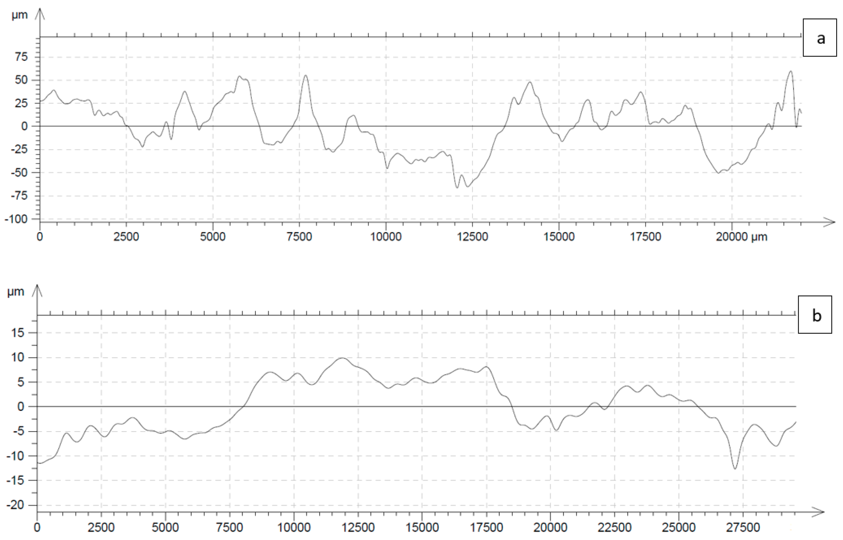
7.8. Surface Roughness Measurement
The surface waviness of the top/bottom sides of the strip was determined using a Nanovea 3D profilometer (Nanovea, Irvine, California, United States). This technique works on the principle of measuring the physical wavelength of light and directly relating it to a specific height. This ensures accurate measurement of surface roughness/finish [
20]. The scan length for all the measurements was 25 mm, whereas the scan speed was 0.1 mm/s. Ten random locations were selected for surface roughness measurements. These locations were randomly selected from all over the strip. The surface profiles are almost identical to one another. The upper surface roughness lies within the 125 μm (0.125 mm) range, as shown in
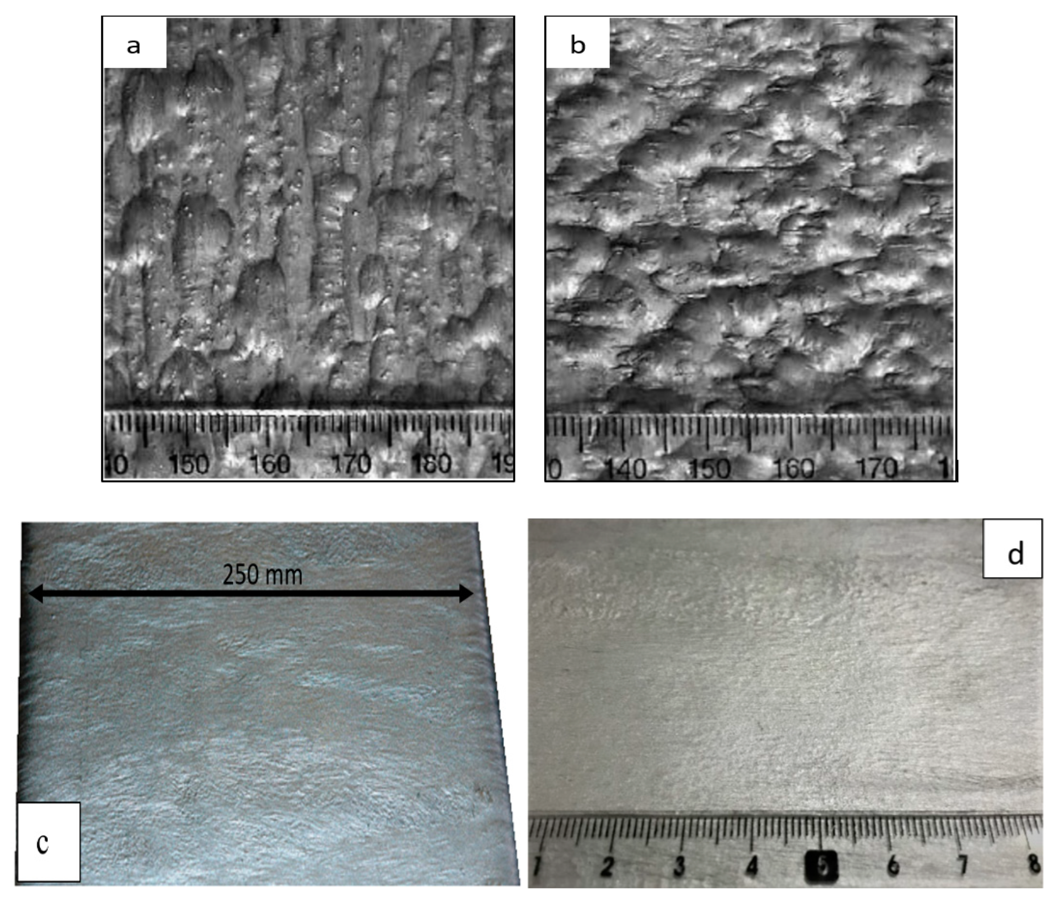
Figure 15a, which is considerably smaller than the DC cast product roughness, i.e., 0.45 mm for AA5182 aluminium alloy (
Figure 16a,b) [
21]. Additionally, pinholes/blowholes were not detected on the surface of the cast strip (
Figure 16c,d), unlike continuously cast products, which possessed defects on their surfaces, and require surface grinding prior to hot rolling [
21].
The strip bottom surface roughness was also measured, and lay in the 20 μm range, as shown in
Figure 15b. As evidenced by the results of the line scans, the bottom surface quality is much superior to the top surface. This fact is credited to the fact that the molten metal is in direct contact with the moving belt, and conforms to its shape, during the solidification process. On the other hand, the top surface of the cast strip is exposed to the atmosphere and is affected by disturbances in the flows of the molten metal.
8. Conclusions
This present paper discusses the casting conditions and analyses results on AA6111 alloy strips, 250 mm wide and 6 mm thick, produced via the HSBC process. Computational fluid dynamics (CFD) analyses were performed to examine molten AA6111 flows in the HSBC process so as to achieve uniform thickness and a good surface finish of the cast strip.
The following conclusions were drawn, using the double impingement with no side dams condition, for the liquid metal feeding system.
Under non-isokinetic feeding, the surface quality of the cast AA6111 alloy strip is not compromised by the generation of surface disturbances.
The AA6111 alloy molten stream shrinks from its two edges. This build-up of the mass around the corners eventually reaches a high terminal velocity. The net inward flow of the molten metal resulted, which filled the center shrinkage depressions.
It was also determined that the inclined refractory plane of the double-impingement metal feeding system has the tendency to lessen, or moderate, the final impact of molten metal with the moving belt, as compared to a single-impingement metal feeding system, where the molten metal encounters an abrupt change in direction by the moving belt.
The swirling flow of the molten metal in an immediate vicinity of the triple point is due to the sudden vertical deceleration of the molten metal by the moving belt. However, the meniscus at the triple point was still observed to be stable and non-fluctuating.
The temperature of the molten metal within the immediate vicinity of the free surface, along the entire length of the simulation domain, remains above the liquidus temperature. Thus, any molten metal discontinuities formed at the free molten metal/air interface had enough time to be damped, prior to solidification.


